Table of Contents
Advertisement
Spyder Model 5
WEB-RxxN ROOM CONTROLLERS
GENERAL INFORMATION
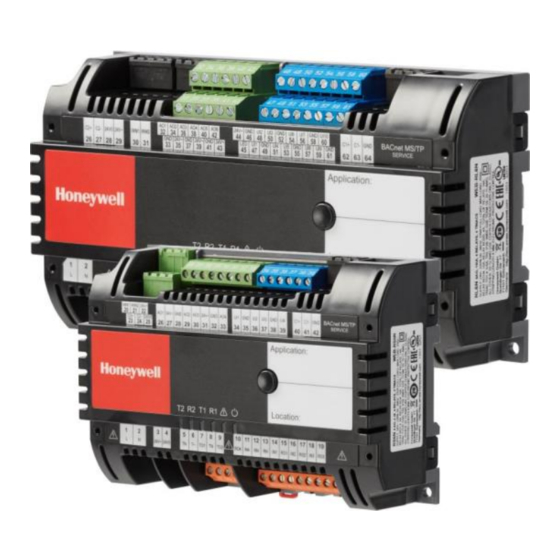
Fig. 1. WEB-RxxN (without optional covers)
large housing
(7-13/16 x 4-5/16 x 2-5/16)
(198 x 110 x 57.5 mm)
small housing
(6-3/8 x 4-5/16 x 2-5/16)
(162 x 110 x 57.5 mm)
See also section "
(A
Relay Current Limitations" on pg. 15.
(B
See also section "Triac Current Limitations" on pg. 12.
CPU: 32-bit MK24FN Freescale Kinetis Cortex M4
®
U.S. Registered Trademark
Copyright © 2019 Honeywell Inc. ▪ All Rights Reserved
Table 1. Overview of models
power
OS no.:
AOs UIs BIs relays
supply
WEB-RL6N 24 VAC
6
WEB-RS5N 24 VAC
4
BEFORE INSTALLATION
IMPORTANT
It is recommended that the unit be kept at room
temperature for at least 24 hours before applying
power; this is to allow the evaporation of any con-
densation resulting from low shipping / storage
temperatures.
US requirement, only: This device must be installed
in a UL-listed enclosure offering adequate space to
maintain the segregation of line voltage field wiring
and Class 2 field wiring.
CAUTION
To avoid electrical shock or equipment damage, you
must switch OFF the power supply before attaching
/ removing connections to/from any terminals.
triacs
(A
10
0
4
4
4
0
4
2
INSTALLATION GUIDE
total no.
remarks
(B
of I/Os
24
72-hr data retention
14
24-hr data retention
31-00281-01 (EN1B-0664GE51 R0819)
Advertisement
Table of Contents

Related Manuals for Honeywell Spyder 5 WEB-RxxN Series


Summary of Contents for Honeywell Spyder 5 WEB-RxxN Series
- Page 1 See also section “ Relay Current Limitations” on pg. 15. See also section "Triac Current Limitations" on pg. 12. CPU: 32-bit MK24FN Freescale Kinetis Cortex M4 ® U.S. Registered Trademark Copyright © 2019 Honeywell Inc. ▪ All Rights Reserved 31-00281-01 (EN1B-0664GE51 R0819)
-
Page 2: Dimensions And Mounting
SPYDER MODEL 5 ROOM CONTROLLERS − INSTALLATION GUIDE DIMENSIONS AND MOUNTING Terminal Protection Covers for IP30 In the case of controllers mounted outside of a cabinet, Housings before applying power to the device, Terminal Protection The controller is available in two housing sizes, both Covers (10-pc. -
Page 3: Terminal Assignment
SPYDER MODEL 5 ROOM CONTROLLERS − INSTALLATION GUIDE When mounted vertically on a DIN rail, the unit must be TERMINAL ASSIGNMENT secured in place with a stopper to prevent sliding. General For a complete list of all terminals and a description of their Wall Mounting/Dismounting functions, see Table 2 and Table 6 on pg. - Page 4 SPYDER MODEL 5 ROOM CONTROLLERS − INSTALLATION GUIDE Table 2. WEB-RS5N Room Controllers: Overview of terminals and functions (by model) WEB- term. printing function RS5N 1, 2 3, 4 24V~, 24V0 Removable 24 VAC power supply input and aux. output voltage (24 VAC) for all triacs 3, 4 24V~, 24V0 Aux.
- Page 5 SPYDER MODEL 5 ROOM CONTROLLERS − INSTALLATION GUIDE Table 4. Universal input types and characteristics type 1 type 2 type 3 UI1, UI2, UI3, UI4, UI7, UI8, UI9, UI1, UI2, UI3 UI5, UI6 UI10 dry contact (closed: res. <10 kΩ; open: res. > 20 kΩ; max. 0.2 Hz; pull-up voltage: 10 V) dry contact (closed: res.
- Page 6 SPYDER MODEL 5 ROOM CONTROLLERS − INSTALLATION GUIDE Table 6. WEB-RL6N Room Controllers: Overview of terminals and functions (by model) term. printing function WEB-RL6N 1, 2 3, 4 24V~, 24V0 Removable 24 VAC power supply input 5, 6 24V~, 24V0 Aux.
- Page 7 SPYDER MODEL 5 ROOM CONTROLLERS − INSTALLATION GUIDE CLCMx WALL MODULE WEB-8000/ CIPer Model 50 ° F Fig. 8. WEB-RS5N (24 VAC models) and example wiring 24V~ CLCMx 7xxxx WALL MODULE 0...10V PROPORTIONAL Niagara DAMPER workbench ACTUATOR TR40x/TR42x TEMP SETP WALL MODULE °F OCCUPANCY CONTACT...
- Page 8 SPYDER MODEL 5 ROOM CONTROLLERS − INSTALLATION GUIDE WEB-8000/ TR40x/TR42x CIPer Model 50 WALL MODULE °F Fig. 10. WEB-RL6N (24 VAC models) and example wiring 31-00281ES-01 (EN1B-0664GE51 R0819)
-
Page 9: Power Supply
SPYDER MODEL 5 ROOM CONTROLLERS − INSTALLATION GUIDE POWER SUPPLY Communication / Signal Terminals All other communication / signal terminals (except for the General Information Sylk Bus – see Table 10 on pg. 15) support 1 x 2.5 mm or 2 x 1.5 mm wiring. -
Page 10: Service Button
Normal operation ON/OFF (0.5 Hz) Stays OFF ANCILLARY WEBs MSTP CONTROLLER (WITH MANUAL MAC ADDRESSING) *Please return the controller for repair. Contact Honeywell WEB-RxxN CONTROLLER (WITH AUTOMATIC MAC ADDRESSING) WEBs Customer Care for assistance. Fig. 12. Automatic MAC addressing In the scenario depicted in Fig.15, some of the controllers... -
Page 11: Communication Interfaces
SPYDER MODEL 5 ROOM CONTROLLERS − INSTALLATION GUIDE maxMaster is set by default to 32 devices (this is ▪ The maxMaster setting will revert to its default value of because some plant controllers support only 32 devices). In the event that you have a plant controller ▪... -
Page 12: Relay Outputs
SPYDER MODEL 5 ROOM CONTROLLERS − INSTALLATION GUIDE Sylk Bus NOTE: If inductive components are to be connected to the relays and if these relays switch more often Sylk Bus-capable devices (e.g., the TR40x / T42x) can be than once every two minutes, these components connected to the controller's Sylk Interface (WEB-RS5N: must be prevented from causing harmful terminals 20 and 21;... -
Page 13: Analog Outputs
SPYDER MODEL 5 ROOM CONTROLLERS − INSTALLATION GUIDE Bias Resistors ▪ any override of the controller by, e.g., pressing the "occupancy" button of the wall module or receipt by the Each universal input is equipped with one bias resistor. See controller of a BACnet MS/TP network command (see Fig.18. - Page 14 SPYDER MODEL 5 ROOM CONTROLLERS − INSTALLATION GUIDE controller's effective occupancy mode. Specifically, the following modes are supported: ▪ UNOCCUPIED: If the wall module's LED is OFF, then the controller is in the "unoccupied" mode. ▪ STANDBY: If the wall module's LED flashes once per sec, then the controller has received a network command and been placed in the "standby"...
- Page 15 SPYDER MODEL 5 ROOM CONTROLLERS − INSTALLATION GUIDE Unoccupied Mode Standby Mode Fig. 157. Example "standby" screens Fig. 146. Example "unoccupied" screens is displayed, the controller is in the "standby" mode. is displayed, the controller is in the "unoccupied" The user can override the "standby" mode by touching the mode.
- Page 16 SPYDER MODEL 5 ROOM CONTROLLERS − INSTALLATION GUIDE LCD of TR42x Configured to Display Info on Fan is displayed, the fan is switched OFF. Depending upon the given application configuration, the effective control mode for underfloor heating, radiator, ceiling heating, and ceiling cooling can then be switched OFF as well.
-
Page 17: Troubleshooting
"Service Button". Construction: independently mounted Check if the Status LED's behavior is changed if you switch control, for panel-mounting the power OFF/ON. Please contact Honeywell if this does not solve the problem. Action: type 1.C Rated impulse voltage: 500 V at 24 V... -
Page 18: Related Technical Literature
SPYDER MODEL 5 ROOM CONTROLLERS − INSTALLATION GUIDE RELATED TECHNICAL LITERATURE Table 11. Related Technical Literature Title Product Literature no. Spyder Model 5 – Mounting Instructions 31-00276ES Spyder Model 5 – Product Data 31-00280ES Spyder Model 5 – Engineering Tool User Guide 31-00282ES TR40x/TR42x –... -
Page 19: Sensor Characteristics
SPYDER MODEL 5 ROOM CONTROLLERS − INSTALLATION GUIDE APPENDIX: SENSOR CHARACTERISTICS Sensor Input Accuracy The controller's internal sensor inputs support NTC10kΩ (Type II) and NTC20kΩ sensors. The following table lists the typical minimum accuracies of the hardware and software for these temperature sensors. Table 12. - Page 20 SPYDER MODEL 5 ROOM CONTROLLERS − INSTALLATION GUIDE NTC 10 kΩ (Type II) Terminal Terminal Terminal Terminal Temp. Resistance Temp. Resistance Temp. Resistance Temp. Resistance voltage voltage voltage voltage °F (°C) [kΩ] °F (°C) [kΩ] °F (°C) [kΩ] °F (°C) [kΩ] 7.904 18.087...
- Page 21 SPYDER MODEL 5 ROOM CONTROLLERS − INSTALLATION GUIDE NTC 20 kΩ Temp. Resistance Terminal Temp. Resistance Terminal Temp. Resistance Terminal Temp. Resistance Terminal °F (°C) [kΩ] voltage °F (°C) [kΩ] voltage °F (°C) [kΩ] voltage °F (°C) [kΩ] voltage -58 (-50) 1659 8.78 37.4 (3)
- Page 22 SPYDER MODEL 5 ROOM CONTROLLERS − INSTALLATION GUIDE PT 1000 Temp. Resistance Terminal Temp. Resistance Terminal Temp. Resistance Terminal Temp. Resistance Terminal °F (°C) [Ω] voltage [V] °F (°C) [Ω] voltage [V] °F (°C) [Ω] voltage [V] °F (°C) [Ω] voltage [V] -58 (-50) 0.312...
- Page 23 SPYDER MODEL 5 ROOM CONTROLLERS − INSTALLATION GUIDE Temp. Resistance Terminal Temp. Resistance Terminal Temp. Resistance Terminal Temp. Resistance Terminal °F (°C) [Ω] voltage [V] °F (°C) [Ω] voltage [V] °F (°C) [Ω] voltage [V] °F (°C) [Ω] voltage [V] 374 (190) 1722 0.647...
- Page 24 SPYDER MODEL 5 ROOM CONTROLLERS − INSTALLATION GUIDE NI1000TK5000 Temp. Resistance Terminal Temp. Resistance Terminal Temp. Resistance Terminal Temp. Resistance Terminal °F (°C) [Ω] voltage [V] °F (°C) [Ω] voltage [V] °F (°C) [Ω] voltage [V] °F (°C) [Ω] voltage [V] 1081.4 0.416 1316.3...
- Page 25 Trademark Information BACnet is a trademark of ASHRAE Inc. Manufactured for and on behalf of the BMS Division of Honeywell Products and Solutions SARL, Z.A. La Pièce, 16, 1180 Rolle, Switzerland by its Authorized Representative: Honeywell Building Technologies Honeywell International Inc.