Nokia 6600 slide Service Manual
Mobile terminal
Hide thumbs
Also See for 6600 slide:
- User manual (59 pages) ,
- Service manual (21 pages) ,
- User manual (48 pages)

Related Manuals for Nokia 6600 slide


Summary of Contents for Nokia 6600 slide
- Page 1 Nokia Customer Care Service Manual RM-414; RM-570 (Nokia 6600/6600i slide; L3&4) Mobile Terminal Part No: (Issue 2) COMPANY CONFIDENTIAL Copyright © 2009 Nokia. All rights reserved.
- Page 2 RM-414; RM-570 Amendment Record Sheet Amendment Record Sheet Amendment No Date Inserted By Comments Issue 1 07/2008 Issue 2 05/2009 RM-570 delta chapter added Page ii COMPANY CONFIDENTIAL Issue 2 Copyright © 2009 Nokia. All rights reserved.
- Page 3 Nokia operates a policy of continuous development. Nokia reserves the right to make changes and improvements to any of the products described in this document without prior notice. Under no circumstances shall Nokia be responsible for any loss of data or income or any special, incidental, consequential or indirect damages howsoever caused.
- Page 4 WCDMA networks and cause problems to 3G cellular phone communication in a wide area. • During testing never activate the GSM or WCDMA transmitter without a proper antenna load, otherwise GSM or WCDMA PA may be damaged. Page iv COMPANY CONFIDENTIAL Issue 2 Copyright © 2009 Nokia. All rights reserved.
- Page 5 Use only approved accessories and batteries. Do not connect incompatible products. CONNECTING TO OTHER DEVICES When connecting to any other device, read its user’s guide for detailed safety instructions. Do not connect incompatible products. Issue 2 COMPANY CONFIDENTIAL Page v Copyright © 2009 Nokia. All rights reserved.
- Page 6 All of the above suggestions apply equally to the product, battery, charger or any accessory. Page vi COMPANY CONFIDENTIAL Issue 2 Copyright © 2009 Nokia. All rights reserved.
- Page 7 RM-414; RM-570 ESD protection ESD protection Nokia requires that service points have sufficient ESD protection (against static electricity) when servicing the phone. Any product of which the covers are removed must be handled with ESD protection. The SIM card can be replaced without ESD protection if the product is otherwise ready for use.
- Page 8 Batteries' performance is particularly limited in temperatures well below freezing. Do not dispose of batteries in a fire! Dispose of batteries according to local regulations (e.g. recycling). Do not dispose as household waste. Page viii COMPANY CONFIDENTIAL Issue 2 Copyright © 2009 Nokia. All rights reserved.
- Page 9 Our policy is of continuous development; details of all technical modifications will be included with service bulletins. While every endeavour has been made to ensure the accuracy of this document, some errors may exist. If any errors are found by the reader, NOKIA MOBILE PHONES Business Group should be notified in writing/e- mail. Please state: •...
- Page 10 RM-414; RM-570 Company policy (This page left intentionally blank.) Page x COMPANY CONFIDENTIAL Issue 2 Copyright © 2009 Nokia. All rights reserved.
- Page 11 RM-414; RM-570 Nokia 6600/6600i slide; L3&4 Service Manual Structure Nokia 6600/6600i slide; L3&4 Service Manual Structure 1 General information 2 Service Devices and Service Concepts 3 BB Troubleshooting and Manual Tuning Guide 4 RF troubleshooting 5 System Module 6 Service information differences between RM-570 and RM-414...
- Page 12 RM-414; RM-570 Nokia 6600/6600i slide; L3&4 Service Manual Structure (This page left intentionally blank.) Page xii COMPANY CONFIDENTIAL Issue 2 Copyright © 2009 Nokia. All rights reserved.
- Page 13 Nokia Customer Care 1 — General information Issue 2 COMPANY CONFIDENTIAL Page 1 –1 Copyright © 2009 Nokia. All rights reserved.
- Page 14 RM-414; RM-570 General information (This page left intentionally blank.) Page 1 –2 COMPANY CONFIDENTIAL Issue 2 Copyright © 2009 Nokia. All rights reserved.
-
Page 15: Table Of Contents
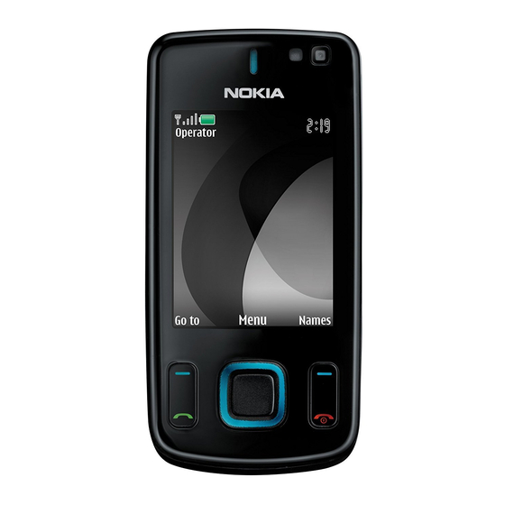
Table 5 Navigation ..............................1–7 Table 6 Memory cards ............................1–7 Table 7 Data cables ..............................1–7 List of Figures Figure 1 RM-414 (Nokia 6600 slide) product picture ..................1–5 Issue 2 COMPANY CONFIDENTIAL Page 1 –3 Copyright © 2009 Nokia. All rights reserved. - Page 16 RM-414; RM-570 General information (This page left intentionally blank.) Page 1 –4 COMPANY CONFIDENTIAL Issue 2 Copyright © 2009 Nokia. All rights reserved.
-
Page 17: Product Selection
RM-414; RM-570 General information Product selection RM-414 (Nokia 6600 slide) is a GSM/WCDMA dual mode phone, supporting EGSM850/900/1800/1900 and WCDMA bands I and V. Figure 1 RM-414 (Nokia 6600 slide) product picture Phone features Display and keypad features • 2.2" TFT display with 320 x 240 pixels and 16M colors •... -
Page 18: Software And User Interface Features
Table 1 Battery and chargers Type Name Note: This phone is charged through the smaller Nokia standard charger interface (2.0 mm plug). A 3.5 mm compatible Nokia standard charger can be used together with the CA-44 charger adapter. BL-4U Battery 1000 mAh Li-Ion... -
Page 19: Table 2 Car Accessories
512 MB microSD card MU-22 1 GB microSD card MU-37 2 GB microSD card MU-41 4 GB microSD card Table 7 Data cables Type Name CA-101 Micro USB cable Issue 2 COMPANY CONFIDENTIAL Page 1 –7 Copyright © 2009 Nokia. All rights reserved. -
Page 20: Technical Specifications
WCDMA V (850): -50 ... +21 dBm/0.01μW ... 251.2mW Number of RF channels GSM850: 124 GSM900: 174 GSM1800: 374 GSM1900: 299 WCDMA I (2100): 277 WCDMA V (850): 108 Page 1 –8 COMPANY CONFIDENTIAL Issue 2 Copyright © 2009 Nokia. All rights reserved. -
Page 21: Battery Endurance
Condensed or dripping water may cause intermittent malfunctions. Protection against dripping water has to be implemented in (enclosure) mechanics. Continuous dampness will cause permanent damage to the module. Issue 2 COMPANY CONFIDENTIAL Page 1 –9 Copyright © 2009 Nokia. All rights reserved. - Page 22 RM-414; RM-570 General information (This page left intentionally blank.) Page 1 –10 COMPANY CONFIDENTIAL Issue 2 Copyright © 2009 Nokia. All rights reserved.
- Page 23 Nokia Customer Care 2 — Service Devices and Service Concepts Issue 2 COMPANY CONFIDENTIAL Page 2 –1 Copyright © 2009 Nokia. All rights reserved.
- Page 24 RM-414; RM-570 Service Devices and Service Concepts (This page left intentionally blank.) Page 2 –2 COMPANY CONFIDENTIAL Issue 2 Copyright © 2009 Nokia. All rights reserved.
-
Page 25: Table Of Contents
2–18 POS (Point of Sale) flash concept ........................2–18 Flash concept with FPS-21..........................2–19 CU-4 flash concept with FPS-21........................2–20 Module jig service concept ..........................2–21 Issue 2 COMPANY CONFIDENTIAL Page 2 –3 Copyright © 2009 Nokia. All rights reserved. - Page 26 Figure 5 Module jig service concept ........................2–21 Figure 6 RF testing concept with RF coupler ....................2–22 Figure 7 Service concept for RF testing and RF/BB tuning ................2–23 Page 2 –4 COMPANY CONFIDENTIAL Issue 2 Copyright © 2009 Nokia. All rights reserved.
-
Page 27: Service Devices
It is used together with the ST-70 rework stencil. RJ-230 Soldering jig RJ-230 is a soldering jig used for soldering and as a rework jig for the engine module. Issue 2 COMPANY CONFIDENTIAL Page 2 –5 Copyright © 2009 Nokia. All rights reserved. -
Page 28: General Devices
The table below gives a short overview of service devices that can be used for testing, error analysis, and repair of product RM-414; RM-570. For the correct use of the service devices, and the best effort of workbench setup, please refer to various concepts. Page 2 –6 COMPANY CONFIDENTIAL Issue 2 Copyright © 2009 Nokia. All rights reserved. - Page 29 4 Connect an FBUS cable (if necessary). 5 Start Phoenix service software. Note: Phoenix enables CU-4 regulators via USB when it is started. Reconnecting the power supply requires a Phoenix restart. Issue 2 COMPANY CONFIDENTIAL Page 2 –7 Copyright © 2009 Nokia. All rights reserved.
- Page 30 FLS-5 is a dongle and flash device incorporated into one package, developed specifically for POS use. Note: FLS-5 can be used as an alternative to PKD-1. Page 2 –8 COMPANY CONFIDENTIAL Issue 2 Copyright © 2009 Nokia. All rights reserved.
-
Page 31: Fps-21
WCDMA network, a shield box is needed in all testing, tuning and fault finding which requires WCDMA RF signal. The shield box is not an active device, it contains only passive filtering components for RF attenuation. Issue 2 COMPANY CONFIDENTIAL Page 2 –9 Copyright © 2009 Nokia. All rights reserved. - Page 32 ST-55 stencil. RJ-160 Rework jig RJ-160 is a rework jig used when servicing the WCDMA duplexer (Z7541). It is used together with the ST-55 stencil. Page 2 –10 COMPANY CONFIDENTIAL Issue 2 Copyright © 2009 Nokia. All rights reserved.
- Page 33 This rework jig takes the FEM or power amplifier (PA) module (N7520) for spreading the soldering paste to the component. Must be used together with the ST-40 stencil. Issue 2 COMPANY CONFIDENTIAL Page 2 –11 Copyright © 2009 Nokia. All rights reserved.
- Page 34 SRT-6 Opening tool SRT-6 is used to open phone covers. Note: The SRT-6 is included in the Nokia Standard Toolkit. Page 2 –12 COMPANY CONFIDENTIAL Issue 2 Copyright © 2009 Nokia. All rights reserved.
- Page 35 SS-93 Opening tool SS-93 is used for opening JAE connectors. Note: The SS-93 is included in Nokia Standard Toolkit. ST-29 rework stencil ST-29 is a rework stencil used when servicing the N3305 component. It is used together with rework jig RJ-73.
- Page 36 SX-4 is a BB5 security device used to protect critical features in tuning and testing. SX-4 is also needed together with FPS-20/FPS-21 when DCT-4 phones are flashed. Page 2 –14 COMPANY CONFIDENTIAL Issue 2 Copyright © 2009 Nokia. All rights reserved.
-
Page 37: Cables
FPS-20/FPS-21 sales packages. CA-35S Power cable CA-35S is a power cable for connecting, for example, the FPS-21 flash prommer to the Point-Of-Sales (POS) flash adapter. Issue 2 COMPANY CONFIDENTIAL Page 2 –15 Copyright © 2009 Nokia. All rights reserved. -
Page 38: Ca-58Rs
The MBUS cable DAU-9S has a modular connector and is used, for example, between the PC's serial port and module jigs, flash adapters or docking station adapters. Note: Docking station adapters valid for DCT4 products. Page 2 –16 COMPANY CONFIDENTIAL Issue 2 Copyright © 2009 Nokia. All rights reserved. - Page 39 The RF cable is used to connect, for example, a module repair jig to the RF measurement equipment. SMA to N-Connector approximately 610 mm. Attenuation for: • GSM850/900: 0.3+-0.1 dB • GSM1800/1900: 0.5+-0.1 dB • WCDMA/WLAN: 0.6+-0.1dB Issue 2 COMPANY CONFIDENTIAL Page 2 –17 Copyright © 2009 Nokia. All rights reserved.
-
Page 40: Service Concepts
Figure 2 POS flash concept Type Description Product specific tools BL-4U Battery Other tools FLS-5 POS flash dongle PC with Phoenix service software Cables DKE-2 USB connectivity cable Page 2 –18 COMPANY CONFIDENTIAL Issue 2 Copyright © 2009 Nokia. All rights reserved. -
Page 41: Flash Concept With Fps-21
Other devices FPS-21 Flash prommer box AC-35 Power supply PK-1/PKD-1 SW security device SS-46 Interface adapter PC with Phoenix service software Cables CA-89DS Service cable USB cable Issue 2 COMPANY CONFIDENTIAL Page 2 –19 Copyright © 2009 Nokia. All rights reserved. -
Page 42: Flash Concept With Fps-21
Flash adapter base SX-4 Smart card (for DCT-4 generation mobile device programming) PC with Phoenix service software Cables PCS-1 Power cable CA-89DS Service cable Standard USB cable Page 2 –20 COMPANY CONFIDENTIAL Issue 2 Copyright © 2009 Nokia. All rights reserved. -
Page 43: Module Jig Service Concept
Flash prommer box PK-1/PKD-1 SW security device SX-4 Smart card PC with VPOS and Phoenix service software Measurement equipment Cables CA-89DS Service cable PCS-1 DC power cable Issue 2 COMPANY CONFIDENTIAL Page 2 –21 Copyright © 2009 Nokia. All rights reserved. - Page 44 Other devices CU-4 Control unit SX-4 Smart card FPS-21 Flash prommer box PK-1/PKD-1 SW security device SS-62 Flash adapter base Measurement equipment PC with Phoenix service software Page 2 –22 COMPANY CONFIDENTIAL Issue 2 Copyright © 2009 Nokia. All rights reserved.
- Page 45 Figure 7 Service concept for RF testing and RF/BB tuning Type Description Product specific devices MJ-183 Module jig Other devices CU-4 Control unit PK-1/PKD-1 SW security device SX-4 Smart card Measurement equipment Issue 2 COMPANY CONFIDENTIAL Page 2 –23 Copyright © 2009 Nokia. All rights reserved.
- Page 46 Type Description Smart card reader PC with Phoenix service software Cables DAU-9S MBUS cable PCS-1 DC power cable XRS-6 RF cable GPIB control cable USB cable Page 2 –24 COMPANY CONFIDENTIAL Issue 2 Copyright © 2009 Nokia. All rights reserved.
- Page 47 Nokia Customer Care 3 — BB Troubleshooting and Manual Tuning Guide Issue 2 COMPANY CONFIDENTIAL Page 3 –1 Copyright © 2009 Nokia. All rights reserved.
- Page 48 RM-414; RM-570 BB Troubleshooting and Manual Tuning Guide (This page left intentionally blank.) Page 3 –2 COMPANY CONFIDENTIAL Issue 2 Copyright © 2009 Nokia. All rights reserved.
- Page 49 3–46 Vibra troubleshooting............................ 3–47 Bluetooth troubleshooting..........................3–49 Baseband manual tuning guide......................... 3–49 Certificate restoring for BB5 products......................3–49 Energy management calibration ........................3–55 List of Tables Issue 2 COMPANY CONFIDENTIAL Page 3 –3 Copyright © 2009 Nokia. All rights reserved.
- Page 50 Figure 14 Differential output waveform of the Ext_in_IHF_out out loop measurement when speaker is connected..............................3–41 Figure 15 Single-ended output waveform of the HP_in_Ext_out loop when microphone is connected. 3–42 Figure 16 Troubleshooting diagram: Bluetooth ....................3–49 Page 3 –4 COMPANY CONFIDENTIAL Issue 2 Copyright © 2009 Nokia. All rights reserved.
-
Page 51: Baseband Self Tests In Phoenix
Always start the troubleshooting procedure by running the Phoenix self tests. If a test fails, please follow the diagram below. Dead or jammed device troubleshooting. If the phone is dead and you cannot perform the self tests, go to Issue 2 COMPANY CONFIDENTIAL Page 3 –5 Copyright © 2009 Nokia. All rights reserved. - Page 52 RM-414; RM-570 BB Troubleshooting and Manual Tuning Guide Troubleshooting flow Page 3 –6 COMPANY CONFIDENTIAL Issue 2 Copyright © 2009 Nokia. All rights reserved.
-
Page 53: Power And Charging Troubleshooting
RM-414; RM-570 BB Troubleshooting and Manual Tuning Guide Power and charging troubleshooting Dead or jammed device troubleshooting Troubleshooting flow Issue 2 COMPANY CONFIDENTIAL Page 3 –7 Copyright © 2009 Nokia. All rights reserved. - Page 54 RM-414; RM-570 BB Troubleshooting and Manual Tuning Guide Troubleshooting flow Page 3 –8 COMPANY CONFIDENTIAL Issue 2 Copyright © 2009 Nokia. All rights reserved.
-
Page 55: General Power Checking
Vibra Only turned off 0/N2100 in "Power off" mode LP3929TMEX- 2.85 SD card Disabled in AACQ/N4802 sleep LIGHT LP5521TMX/ Key light, top N2401 light alive light Issue 2 COMPANY CONFIDENTIAL Page 3 –9 Copyright © 2009 Nokia. All rights reserved. -
Page 56: Dc Charging Troubleshooting
RM-414; RM-570 BB Troubleshooting and Manual Tuning Guide DC charging troubleshooting Troubleshooting flow Page 3 –10 COMPANY CONFIDENTIAL Issue 2 Copyright © 2009 Nokia. All rights reserved. -
Page 57: Interface Troubleshooting
RM-414; RM-570 BB Troubleshooting and Manual Tuning Guide Interface troubleshooting Flash programming fault troubleshooting Part 1 Issue 2 COMPANY CONFIDENTIAL Page 3 –11 Copyright © 2009 Nokia. All rights reserved. - Page 58 RM-414; RM-570 BB Troubleshooting and Manual Tuning Guide Part 2 Figure 8 Flashing pic 1. Take single trig measurement for the rise of the BSI signal. Page 3 –12 COMPANY CONFIDENTIAL Issue 2 Copyright © 2009 Nokia. All rights reserved.
- Page 59 RM-414; RM-570 BB Troubleshooting and Manual Tuning Guide Figure 9 Flashing pic 2. Take single trig measurement for the rise of the BSI signal. Issue 2 COMPANY CONFIDENTIAL Page 3 –13 Copyright © 2009 Nokia. All rights reserved.
-
Page 60: Combo Memory Troubleshooting
RM-414; RM-570 BB Troubleshooting and Manual Tuning Guide Combo memory troubleshooting Troubleshooting flow Page 3 –14 COMPANY CONFIDENTIAL Issue 2 Copyright © 2009 Nokia. All rights reserved. -
Page 61: Sd Card Troubleshooting
RM-414; RM-570 BB Troubleshooting and Manual Tuning Guide SD card troubleshooting Troubleshooting flow Issue 2 COMPANY CONFIDENTIAL Page 3 –15 Copyright © 2009 Nokia. All rights reserved. -
Page 62: Usb Interface Troubleshooting
RM-414; RM-570 BB Troubleshooting and Manual Tuning Guide USB interface troubleshooting Troubleshooting flow Page 3 –16 COMPANY CONFIDENTIAL Issue 2 Copyright © 2009 Nokia. All rights reserved. -
Page 63: Sim Card Troubleshooting
RM-414; RM-570 BB Troubleshooting and Manual Tuning Guide SIM card troubleshooting Troubleshooting flow Issue 2 COMPANY CONFIDENTIAL Page 3 –17 Copyright © 2009 Nokia. All rights reserved. -
Page 64: User Interface Troubleshooting
If one or more keys are stuck, so that the key does not react when a keydome key is pressed, the failure is caused by mechanical reasons (dirt, rust, mechanical damage, etc.) If the failure mode is not clear, start with the Keyboard test in Phoenix. Troubleshooting flow Page 3 –18 COMPANY CONFIDENTIAL Issue 2 Copyright © 2009 Nokia. All rights reserved. -
Page 65: Power Key Troubleshooting
RM-414; RM-570 BB Troubleshooting and Manual Tuning Guide Power key troubleshooting Troubleshooting flow Issue 2 COMPANY CONFIDENTIAL Page 3 –19 Copyright © 2009 Nokia. All rights reserved. -
Page 66: Accelerometer Self Test Troubleshooting
RM-414; RM-570 BB Troubleshooting and Manual Tuning Guide Accelerometer self test troubleshooting Troubleshooting flow Page 3 –20 COMPANY CONFIDENTIAL Issue 2 Copyright © 2009 Nokia. All rights reserved. -
Page 67: Display Module Troubleshooting
White Dot Total Combined Not allowed. defect counts Two single dot defects that are within 5 mm of each other should be interpreted as combined dot defect. Issue 2 COMPANY CONFIDENTIAL Page 3 –21 Copyright © 2009 Nokia. All rights reserved. -
Page 68: Display Troubleshooting
When assembling/disassembling the phone, all grounding contacts between different levels (display, display flex, display frame, BTBl connector) must be checked in order to have them properly connected. Page 3 –22 COMPANY CONFIDENTIAL Issue 2 Copyright © 2009 Nokia. All rights reserved. - Page 69 RM-414; RM-570 BB Troubleshooting and Manual Tuning Guide Troubleshooting flow Issue 2 COMPANY CONFIDENTIAL Page 3 –23 Copyright © 2009 Nokia. All rights reserved.
-
Page 70: Display Backlight Troubleshooting
Display backlight troubleshooting Troubleshooting flow Ambient light sensor (ALS) troubleshooting Prerequisites Keyboard backlight troubleshooting before continuing with the ALS Make sure that you have completed the troubleshooting. Page 3 –24 COMPANY CONFIDENTIAL Issue 2 Copyright © 2009 Nokia. All rights reserved. - Page 71 3 Open Tools→Ambient Light Sensor calibration window 4 Ensure that Use default values only flag is set 5 Click Write Figure 10 Ambient light sensor calibration window Issue 2 COMPANY CONFIDENTIAL Page 3 –25 Copyright © 2009 Nokia. All rights reserved.
- Page 72 RM-414; RM-570 BB Troubleshooting and Manual Tuning Guide Figure 11 Display test Figure 12 ADC readings Page 3 –26 COMPANY CONFIDENTIAL Issue 2 Copyright © 2009 Nokia. All rights reserved.
- Page 73 RM-414; RM-570 BB Troubleshooting and Manual Tuning Guide Troubleshooting flow Issue 2 COMPANY CONFIDENTIAL Page 3 –27 Copyright © 2009 Nokia. All rights reserved.
-
Page 74: Camera Module Troubleshooting
• Analyse the picture from your PC monitor, full colour setting is recommended • If possible, compare with a picture of the same motive taken with a similar Nokia device • If camera has auto focus: Remember that the white focussing frame which appears when the camera button is pressed halfway down, must turn green for auto focus lock. -
Page 75: Main Camera Troubleshooting
RM-414; RM-570 BB Troubleshooting and Manual Tuning Guide Main camera troubleshooting Troubleshooting flow Issue 2 COMPANY CONFIDENTIAL Page 3 –29 Copyright © 2009 Nokia. All rights reserved. -
Page 76: Main Camera Bad Image Quality Troubleshooting
RM-414; RM-570 BB Troubleshooting and Manual Tuning Guide Main camera bad image quality troubleshooting Troubleshooting flow Page 3 –30 COMPANY CONFIDENTIAL Issue 2 Copyright © 2009 Nokia. All rights reserved. -
Page 77: Main Camera Viewfinder Troubleshooting
RM-414; RM-570 BB Troubleshooting and Manual Tuning Guide Main camera viewfinder troubleshooting Troubleshooting flow Issue 2 COMPANY CONFIDENTIAL Page 3 –31 Copyright © 2009 Nokia. All rights reserved. -
Page 78: Main Camera Hardware Failure Message Troubleshooting
RM-414; RM-570 BB Troubleshooting and Manual Tuning Guide Main camera hardware failure message troubleshooting Troubleshooting flow Page 3 –32 COMPANY CONFIDENTIAL Issue 2 Copyright © 2009 Nokia. All rights reserved. -
Page 79: Main Camera Hardware Troubleshooting
RM-414; RM-570 BB Troubleshooting and Manual Tuning Guide Main camera hardware troubleshooting Troubleshooting flow Issue 2 COMPANY CONFIDENTIAL Page 3 –33 Copyright © 2009 Nokia. All rights reserved. -
Page 80: Led Camera Flash Troubleshooting
When Note: Always use the "troubled" phone when evaluating a picture in a video call. Do not evaluate the picture on the receiving phone. Page 3 –34 COMPANY CONFIDENTIAL Issue 2 Copyright © 2009 Nokia. All rights reserved. - Page 81 BB Troubleshooting and Manual Tuning Guide • The center of the picture is sharper than the edges • If possible, compare with the picture on another Nokia device in a videocall, and of the same motive. Issue 2 COMPANY CONFIDENTIAL Page 3 –35...
-
Page 82: Secondary Camera Bad Image Quality Troubleshooting
RM-414; RM-570 BB Troubleshooting and Manual Tuning Guide Secondary camera bad image quality troubleshooting Troubleshooting flow Page 3 –36 COMPANY CONFIDENTIAL Issue 2 Copyright © 2009 Nokia. All rights reserved. -
Page 83: Secondary Camera Troubleshooting
Phone must be in a video call for the front camera to be active. Note: Always use the "troubled" phone when evaluating a picture in a video call. Do not evaluate the picture on the receiving phone. Issue 2 COMPANY CONFIDENTIAL Page 3 –37 Copyright © 2009 Nokia. All rights reserved. - Page 84 RM-414; RM-570 BB Troubleshooting and Manual Tuning Guide Page 3 –38 COMPANY CONFIDENTIAL Issue 2 Copyright © 2009 Nokia. All rights reserved.
-
Page 85: Audio Troubleshooting
Earpiece, internal microphone and speaker are in place during measurement. Applying a headset accessory during measurement causes a significant drop in measured quantities. The gain values presented in the table apply for a differential output vs. single-ended/differential input. Issue 2 COMPANY CONFIDENTIAL Page 3 –39 Copyright © 2009 Nokia. All rights reserved. - Page 86 (OUT/GND) HSEAR R N and GND HSEAR P, HSEAR N and GND HSEAR R P, HSEAR R N and GND HSEAR P, HSEAR N and GND Page 3 –40 COMPANY CONFIDENTIAL Issue 2 Copyright © 2009 Nokia. All rights reserved.
- Page 87 If a special low-pass filter designed for measuring digital amplifiers is unavailable, the measurement must be performed with a current probe and the input signal frequency must be 2kHz. Figure 14 Differential output waveform of the Ext_in_IHF_out out loop measurement when speaker is connected. Issue 2 COMPANY CONFIDENTIAL Page 3 –41 Copyright © 2009 Nokia. All rights reserved.
- Page 88 RM-414; RM-570 BB Troubleshooting and Manual Tuning Guide Figure 15 Single-ended output waveform of the HP_in_Ext_out loop when microphone is connected. Page 3 –42 COMPANY CONFIDENTIAL Issue 2 Copyright © 2009 Nokia. All rights reserved.
-
Page 89: Internal Earpiece Troubleshooting
RM-414; RM-570 BB Troubleshooting and Manual Tuning Guide Internal earpiece troubleshooting Troubleshooting flow Issue 2 COMPANY CONFIDENTIAL Page 3 –43 Copyright © 2009 Nokia. All rights reserved. -
Page 90: Internal Microphone Troubleshooting
RM-414; RM-570 BB Troubleshooting and Manual Tuning Guide Internal microphone troubleshooting Troubleshooting flow Page 3 –44 COMPANY CONFIDENTIAL Issue 2 Copyright © 2009 Nokia. All rights reserved. -
Page 91: Internal Handsfree (Ihf) Troubleshooting
RM-414; RM-570 BB Troubleshooting and Manual Tuning Guide Internal handsfree (IHF) troubleshooting Troubleshooting flow Issue 2 COMPANY CONFIDENTIAL Page 3 –45 Copyright © 2009 Nokia. All rights reserved. -
Page 92: External Earpiece Troubleshooting
RM-414; RM-570 BB Troubleshooting and Manual Tuning Guide External earpiece troubleshooting Troubleshooting flow Page 3 –46 COMPANY CONFIDENTIAL Issue 2 Copyright © 2009 Nokia. All rights reserved. -
Page 93: External Microphone Troubleshooting
RM-414; RM-570 BB Troubleshooting and Manual Tuning Guide External microphone troubleshooting Troubleshooting flow Issue 2 COMPANY CONFIDENTIAL Page 3 –47 Copyright © 2009 Nokia. All rights reserved. -
Page 94: Vibra Troubleshooting
RM-414; RM-570 BB Troubleshooting and Manual Tuning Guide Vibra troubleshooting Troubleshooting flow Page 3 –48 COMPANY CONFIDENTIAL Issue 2 Copyright © 2009 Nokia. All rights reserved. -
Page 95: Bluetooth Troubleshooting
This procedure is performed when the device certificate is corrupted for some reason. All tunings (RF & Baseband, UI) must be done after performing the certificate restoring procedure. Issue 2 COMPANY CONFIDENTIAL Page 3 –49 Copyright © 2009 Nokia. All rights reserved. - Page 96 Note: USB flashing does not work for a dead BB5 phone. • Create a request file. • Send the file to Nokia by e-mail. Use the following addresses depending on your location: • APAC: sydney.service@nokia.com • CHINA: repair.ams@nokia.com • E&A: salo.repair@nokia.com •...
- Page 97 Flash Type must be set to Phone as Manufactured. To continue, click Start. Progress bars and messages on the screen show actions during phone programming, please wait. Issue 2 COMPANY CONFIDENTIAL Page 3 –51 Copyright © 2009 Nokia. All rights reserved.
- Page 98 Phoenix , choose File→Scan Product . To connect the phone with ii Choose Tools→Certificate Restore . iii To choose a location for the request file, click Browse. Page 3 –52 COMPANY CONFIDENTIAL Issue 2 Copyright © 2009 Nokia. All rights reserved.
- Page 99 Request file, click Start. To create the vi When the file for certificate restore has been created, send it to Nokia as an e-mail attachment. 3. Restore certificate. For this procedure, you must supply +12 V to CU-4 from an external power supply.
- Page 100 To write the file to phone, click Start. Next actions Phoenix tuning functions. After a successful rewrite, you must retune the phone completely by using Important: Perform all tunings: RF, BB, and UI. Page 3 –54 COMPANY CONFIDENTIAL Issue 2 Copyright © 2009 Nokia. All rights reserved.
-
Page 101: Energy Management Calibration
Write and/or repeat the procedure again. Energy Management Calibration window. 10. To end the procedure, close the Issue 2 COMPANY CONFIDENTIAL Page 3 –55 Copyright © 2009 Nokia. All rights reserved. - Page 102 RM-414; RM-570 BB Troubleshooting and Manual Tuning Guide (This page left intentionally blank.) Page 3 –56 COMPANY CONFIDENTIAL Issue 2 Copyright © 2009 Nokia. All rights reserved.
- Page 103 Nokia Customer Care 4 — RF troubleshooting Issue 2 COMPANY CONFIDENTIAL Page 4 –1 Copyright © 2009 Nokia. All rights reserved.
- Page 104 RM-414; RM-570 RF troubleshooting (This page left intentionally blank.) Page 4 –2 COMPANY CONFIDENTIAL Issue 2 Copyright © 2009 Nokia. All rights reserved.
- Page 105 Tx LO leakage (WCDMA) ..........................4–50 List of Tables Table 12 Rf channel filter calibration tuning limits ..................4–29 Table 13 RF tuning limits in Rx calibration....................... 4–31 Issue 2 COMPANY CONFIDENTIAL Page 4 –3 Copyright © 2009 Nokia. All rights reserved.
- Page 106 Figure 26 Pop-up window for WCDMA2100...................... 4–40 Figure 27 Pop-up window for WCDMA2100...................... 4–42 Figure 28 WCDMA power level tuning steps ..................... 4–44 Figure 29 High burst measurement ........................4–46 Page 4 –4 COMPANY CONFIDENTIAL Issue 2 Copyright © 2009 Nokia. All rights reserved.
-
Page 107: General Rf Troubleshooting
The scope of this guideline is to enable repairs at key-component level. Some key-components are not Non- accessible without replacing the whole shield frame (i.e. not replaceable). Please refer to section replaceable RF components . Issue 2 COMPANY CONFIDENTIAL Page 4 –5 Copyright © 2009 Nokia. All rights reserved. -
Page 108: Rf Key Components
Figure 17 RF key components Non-replaceable RF components Because of their location on the PWB, the following RF components cannot be replaced without replacing the whole shield frame: Page 4 –6 COMPANY CONFIDENTIAL Issue 2 Copyright © 2009 Nokia. All rights reserved. -
Page 109: General Voltage Checking
Vbat at WCDMA PA C7547 3.9 V Supply input to DC/DC conv L7592 3.9 V * With these settings, the result should be 1.3 V. Issue 2 COMPANY CONFIDENTIAL Page 4 –7 Copyright © 2009 Nokia. All rights reserved. -
Page 110: Phoenix Self Tests
Dead or jammed device troubleshooting. If the phone is dead and you cannot perform the self tests, go to in the baseband troubleshooting section. Page 4 –8 COMPANY CONFIDENTIAL Issue 2 Copyright © 2009 Nokia. All rights reserved. - Page 111 RM-414; RM-570 RF troubleshooting Troubleshooting flow Issue 2 COMPANY CONFIDENTIAL Page 4 –9 Copyright © 2009 Nokia. All rights reserved.
-
Page 112: Vctcxo Troubleshooting
RM-414; RM-570 RF troubleshooting VCTCXO troubleshooting Troubleshooting flow Page 4 –10 COMPANY CONFIDENTIAL Issue 2 Copyright © 2009 Nokia. All rights reserved. -
Page 113: Receiver Troubleshooting
GSM RX chain activation for manual measurements / received signal. For GSM RSSI measurements, see section GSM RSSI measurement . For a similar test in WCDMA mode, see section WCDMA RSSI measurement . Issue 2 COMPANY CONFIDENTIAL Page 4 –11 Copyright © 2009 Nokia. All rights reserved. -
Page 114: Rx Gsm850 Troubleshooting
RM-414; RM-570 RF troubleshooting RX GSM850 troubleshooting Troubleshooting flow Page 4 –12 COMPANY CONFIDENTIAL Issue 2 Copyright © 2009 Nokia. All rights reserved. -
Page 115: Rx Gsm900 Troubleshooting
RM-414; RM-570 RF troubleshooting RX GSM900 troubleshooting Troubleshooting flow Issue 2 COMPANY CONFIDENTIAL Page 4 –13 Copyright © 2009 Nokia. All rights reserved. -
Page 116: Rx Gsm1800 Troubleshooting
RM-414; RM-570 RF troubleshooting RX GSM1800 troubleshooting Troubleshooting flow Page 4 –14 COMPANY CONFIDENTIAL Issue 2 Copyright © 2009 Nokia. All rights reserved. -
Page 117: Rx Gsm1900 Troubleshooting
RM-414; RM-570 RF troubleshooting RX GSM1900 troubleshooting Troubleshooting flow Issue 2 COMPANY CONFIDENTIAL Page 4 –15 Copyright © 2009 Nokia. All rights reserved. -
Page 118: Gsm Rx Chain Activation For Manual Measurements/Gsm Rssi Measurement
The reading should reflect the level of the signal generator (-losses) +/- 5 dB. When varying the level in the range -30 to -102 dBm the reading should then follow within +/-5 dB. Page 4 –16 COMPANY CONFIDENTIAL Issue 2 Copyright © 2009 Nokia. All rights reserved. -
Page 119: Wcdma Receiver Troubleshooting
RM-414; RM-570 RF troubleshooting WCDMA receiver troubleshooting Troubleshooting flow Issue 2 COMPANY CONFIDENTIAL Page 4 –17 Copyright © 2009 Nokia. All rights reserved. -
Page 120: Wcdma Rx Chain Activation For Manual Measurement
If the settings are changed later on (for example, change of channel) you have to click Stop and Start again. Note: Clicking Stop also disables TX control if it was active. 4. Set the following RF generator settings: Page 4 –18 COMPANY CONFIDENTIAL Issue 2 Copyright © 2009 Nokia. All rights reserved. -
Page 121: Wcdma Rssi Measurement
• The most useful Phoenix tool for GSM transmitter testing is “RF Controls”; in WCDMA transmitter testing the best tool is “TX Control”. • Remember that re-tuning is not a fix! Phones are tuned correctly in production Issue 2 COMPANY CONFIDENTIAL Page 4 –19 Copyright © 2009 Nokia. All rights reserved. -
Page 122: Gsm Transmitter Troubleshooting
2. Activate RF controls in Phoenix (Testing→GSM→Rf Controls ). Use the following settings: 3. Check the basic TX parameters (i.e. power, phase error, modulation and switching spectrum), using a communication analyser (for example CMU200). Page 4 –20 COMPANY CONFIDENTIAL Issue 2 Copyright © 2009 Nokia. All rights reserved. - Page 123 You can troubleshoot the GSM transmitter for each GSM band separately, one band at a time. If you want to troubleshoot GSM850, GSM1800 or GSM1900, change the band with the RF controls and set the communication analyser accordingly. Issue 2 COMPANY CONFIDENTIAL Page 4 –21 Copyright © 2009 Nokia. All rights reserved.
-
Page 124: Tx 850/900 Troubleshooting
RM-414; RM-570 RF troubleshooting TX 850/900 troubleshooting Troubleshooting flow Page 4 –22 COMPANY CONFIDENTIAL Issue 2 Copyright © 2009 Nokia. All rights reserved. -
Page 125: Tx 1800/1900 Troubleshooting
RM-414; RM-570 RF troubleshooting TX 1800/1900 troubleshooting Troubleshooting flow Issue 2 COMPANY CONFIDENTIAL Page 4 –23 Copyright © 2009 Nokia. All rights reserved. -
Page 126: Checking Antenna Functionality
WCDMA transmitter troubleshooting Steps 1. Set the phone to local mode. 2. In Phoenix, select Testing→WCDMA→TX control . 3. Use the following settings in the TX control window: Page 4 –24 COMPANY CONFIDENTIAL Issue 2 Copyright © 2009 Nokia. All rights reserved. - Page 127 4. Click Send to enable the settings and activate TX. If settings are changed (eg. new channel), you have to click RF Stop and Send again. 5. Use the CMU200 to check the WCDMA power. Issue 2 COMPANY CONFIDENTIAL Page 4 –25 Copyright © 2009 Nokia. All rights reserved.
- Page 128 RM-414; RM-570 RF troubleshooting Figure 23 WCDMA power window Page 4 –26 COMPANY CONFIDENTIAL Issue 2 Copyright © 2009 Nokia. All rights reserved.
-
Page 129: Wcdma Transmitter Troubleshooting Flowchart
RM-414; RM-570 RF troubleshooting WCDMA transmitter troubleshooting flowchart Troubleshooting flow RF tunings Introduction to RF tunings Important: Only perform RF tunings if: Issue 2 COMPANY CONFIDENTIAL Page 4 –27 Copyright © 2009 Nokia. All rights reserved. -
Page 130: Autotuning For Bb5
Install the phone-specific data package. This defines the phone-specific settings. Auto tuning procedure 1 Make sure the phone (in the jig) is connected to the equipment. Else, some menus will not be shown in Phoenix. Page 4 –28 COMPANY CONFIDENTIAL Issue 2 Copyright © 2009 Nokia. All rights reserved. -
Page 131: System Mode Independent Manual Tunings
The PA detection procedure detects which PA manufacturer is used for phone PAs. If a PA is changed or if the permanent memory (PMM) data is corrupted, PA detection has to be performed before Tx tunings. Issue 2 COMPANY CONFIDENTIAL Page 4 –29 Copyright © 2009 Nokia. All rights reserved. -
Page 132: Gsm Receiver Tunings
1. Connect the GSM connector of the module jig to a signal generator. Phoenix service software. 2. Start 3. From the Operating mode drop-down menu, set mode to Local. 4. Choose Tuning→GSM→Rx Calibration . 5. Click Start. Page 4 –30 COMPANY CONFIDENTIAL Issue 2 Copyright © 2009 Nokia. All rights reserved. - Page 133 Table 13 RF tuning limits in Rx calibration Unit GSM850 AFC Value (init) -200 -80..40 AFC slope 108..121 RSSI (AGC-0) 107..110 GSM900 AFC Value (init) -200 -105..62 AFC slope RSSI (AGC-0) 107...110 GSM1800 Issue 2 COMPANY CONFIDENTIAL Page 4 –31 Copyright © 2009 Nokia. All rights reserved.
-
Page 134: Rx Band Filter Response Compensation (Gsm)
On each GSM Rx band, there is a band filter in front of the RF ASIC front end. The amplitude ripple caused by these filters causes ripple to the RSSI measurement, and therefore calibration is needed. Page 4 –32 COMPANY CONFIDENTIAL Issue 2 Copyright © 2009 Nokia. All rights reserved. - Page 135 From the Operating mode drop-down menu, set mode to Local. Select GSM900 band. Choose Tuning→GSM→Rx Band Filter Response Compensation . Select Tuning mode: manual Click Start. Issue 2 COMPANY CONFIDENTIAL Page 4 –33 Copyright © 2009 Nokia. All rights reserved.
- Page 136 10. Go through all 9 frequencies. The following table will be shown: 11. Check that the tuning values are within the limits specified in the following table: Unit GSM850 Ch. 118/867.26771 MHz Ch. 128/869.26771 MHz Page 4 –34 COMPANY CONFIDENTIAL Issue 2 Copyright © 2009 Nokia. All rights reserved.
- Page 137 Ch. 512 / 1930.26771 MHz Ch. 537 / 1935.26771 MHz Ch. 586 / 1945.06771 MHz Ch. 661 / 1960.06771 MHz Ch. 736 / 1975.06771 MHz Ch. 794 / 1986.66771 MHz Issue 2 COMPANY CONFIDENTIAL Page 4 –35 Copyright © 2009 Nokia. All rights reserved.
-
Page 138: Gsm Transmitter Tunings
3. Choose Tuning→GSM→Tx IQ Tuning . 4. Select Mode: Automatic. 5. Select Band: GSM900 and click Start. 6. Click Next to start GSM1800 band TX IQ tuning. Page 4 –36 COMPANY CONFIDENTIAL Issue 2 Copyright © 2009 Nokia. All rights reserved. -
Page 139: Tx Power Level Tuning (Gsm)
Connect the phone to a spectrum analyzer. Phoenix service software. Start From the Operating mode drop-down menu, set mode to Local. Choose Tuning→GSM→Tx Power Level Tuning . Issue 2 COMPANY CONFIDENTIAL Page 4 –37 Copyright © 2009 Nokia. All rights reserved. - Page 140 Reference level 33dBm A power meter with a peak power detector can be also used. Remember to take the attenuations into account. Page 4 –38 COMPANY CONFIDENTIAL Issue 2 Copyright © 2009 Nokia. All rights reserved.
- Page 141 10. Adjust power for all bold power levels to correspond the Target dBm column by pressing + or – keys. Next actions Continue tuning the bold power levels of the GSM900, GSM1800 and GSM1900 bands. You will see this message, if finished successfully: Issue 2 COMPANY CONFIDENTIAL Page 4 –39 Copyright © 2009 Nokia. All rights reserved.
-
Page 142: Wcdma Receiver Tunings
5. Click Tune. Rx Calibration pop-up window and click 6. Setup the signal generator to correspond with the values on the, Figure 26 Pop-up window for WCDMA2100 Page 4 –40 COMPANY CONFIDENTIAL Issue 2 Copyright © 2009 Nokia. All rights reserved. - Page 143 • In the Tuning menu, choose WCDMA→ Rx Calibration . • Click Start. • Select Band, "WCDMA2100 or WCDMA850". • Check the Sweep Mode box. • Click Tune. Issue 2 COMPANY CONFIDENTIAL Page 4 –41 Copyright © 2009 Nokia. All rights reserved.
-
Page 144: Wcdma Transmitter Tunings
From the Operating mode drop-down menu, set mode to Local. Choose Tuning→WCDMA→Tx AGC & Power Detector. Click Start. Wide Range pane, click Tune (the leftmost Tune button). In the Page 4 –42 COMPANY CONFIDENTIAL Issue 2 Copyright © 2009 Nokia. All rights reserved. - Page 145 It must be possible to measure power levels down to –68 dBm. The measured power levels must be monotonously decreasing. Make sure that the marker is not measuring the level of noise spikes on lower levels. Issue 2 COMPANY CONFIDENTIAL Page 4 –43 Copyright © 2009 Nokia. All rights reserved.
- Page 146 RM-414; RM-570 RF troubleshooting Figure 28 WCDMA power level tuning steps Page 4 –44 COMPANY CONFIDENTIAL Issue 2 Copyright © 2009 Nokia. All rights reserved.
- Page 147 Fill in the power level values (in dBm) to the Wide Range pane, click Calculate. In the High Burst pane, click Tune. 10. In the 11. Adjust the spectrum analyzer according to the following settings: Issue 2 COMPANY CONFIDENTIAL Page 4 –45 Copyright © 2009 Nokia. All rights reserved.
- Page 148 14. Check that the calculated values are within the limits specified in the following table: C0-high -0.5 C1-high C2-high C0-mid -0.7 C1-mid C2-mid C0-low C1-low -400 C2-low -10000 15000 Page 4 –46 COMPANY CONFIDENTIAL Issue 2 Copyright © 2009 Nokia. All rights reserved.
- Page 149 Reference level: 24 dBm or -20 dBm depending on the level measured Input attenuation: Automatic Resolution bandwidth: 5 MHz Video bandwidth: 5 MHz Sweep time: 20 ms Issue 2 COMPANY CONFIDENTIAL Page 4 –47 Copyright © 2009 Nokia. All rights reserved.
-
Page 150: Tx Band Response Calibration (Wcdma)
• The Read button reads the tuned values in the PM of the terminal, and displays them in the Tuned Values pane in in the Current column. Steps Phoenix service software. Start Page 4 –48 COMPANY CONFIDENTIAL Issue 2 Copyright © 2009 Nokia. All rights reserved. - Page 151 The tuned values are shown in the 16. Check that the tuned values are within the limits presented in the following table. If they are OK, click Yes. Issue 2 COMPANY CONFIDENTIAL Page 4 –49 Copyright © 2009 Nokia. All rights reserved.
-
Page 152: Tx Lo Leakage (Wcdma)
1. From the Operating mode drop-down menu, set mode to Local. 2. Choose Tuning→WCDMA→ Tx LO Leakage . 3. Click Tune. 4. To end the tuning, click Close. Page 4 –50 COMPANY CONFIDENTIAL Issue 2 Copyright © 2009 Nokia. All rights reserved. - Page 153 Nokia Customer Care 5 — System Module Issue 2 COMPANY CONFIDENTIAL Page 5 –1 Copyright © 2009 Nokia. All rights reserved.
- Page 154 RM-414; RM-570 System Module (This page left intentionally blank.) Page 5 –2 COMPANY CONFIDENTIAL Issue 2 Copyright © 2009 Nokia. All rights reserved.
- Page 155 Figure 36 MicroSD card interface ........................5–13 Figure 37 Backlight and illumination interface....................5–14 Figure 38 Audio interface ........................... 5–16 Figure 39 Bluetooth interface ..........................5–17 Issue 2 COMPANY CONFIDENTIAL Page 5 –3 Copyright © 2009 Nokia. All rights reserved.
- Page 156 RM-414; RM-570 System Module (This page left intentionally blank.) Page 5 –4 COMPANY CONFIDENTIAL Issue 2 Copyright © 2009 Nokia. All rights reserved.
-
Page 157: Introduction
Hall IC switch/position sensor N2550 Battery BL-4U Battery connector Tabby blade interface X2070 MicroSD connector X4800 MicroUSB connector X2001 BTB connector Coax board-to-board connector X3300 RF connector X7800 Issue 2 COMPANY CONFIDENTIAL Page 5 –5 Copyright © 2009 Nokia. All rights reserved. - Page 158 RM-414; RM-570 System Module Key component placement Page 5 –6 COMPANY CONFIDENTIAL Issue 2 Copyright © 2009 Nokia. All rights reserved.
- Page 159 RM-414; RM-570 System Module System module block diagram Issue 2 COMPANY CONFIDENTIAL Page 5 –7 Copyright © 2009 Nokia. All rights reserved.
- Page 160 RM-414; RM-570 System Module Board and module connections Page 5 –8 COMPANY CONFIDENTIAL Issue 2 Copyright © 2009 Nokia. All rights reserved.
-
Page 161: Energy Management
The BSI line is used to recognize the battery capacity by a battery internal pull down resistor. Figure 31 Blade battery connector Charging This phone is charged through the smaller Nokia standard interface (2.0 mm plug). The wider standard charger (3.5 mm) can be used together with the CA-44 charger adapter. Issue 2 COMPANY CONFIDENTIAL Page 5 –9... -
Page 162: Normal And Extreme Voltages
Charging a dead battery Charging of a dead battery has to be carried out via an approved NOKIA charger. Charging of a dead battery via a PC is not allowed since this procedure is not including a current regulator (the battery can be charged with a too high current level). -
Page 163: Power Key And System Power-Up
SMPS Clk is 2.4 MHz clock line from RAP to EM ASIC N2300. In deep sleep mode, when VCTCXO is off, this signal is set to '0'-state. BT Clk is 38.4 MHz signal from Ahneus ASIC to BT module. Figure 33 Clocking scheme Issue 2 COMPANY CONFIDENTIAL Page 5 –11 Copyright © 2009 Nokia. All rights reserved. -
Page 164: Usb, Sim, Microsd
The SIM interface supports both 1.8 V and 3.0 V SIM cards. The SIM interface voltage is first 1.8 V when the SIM card is inserted, and if the card does not response to the ATR a 3 V interface voltage is used. Page 5 –12 COMPANY CONFIDENTIAL Issue 2 Copyright © 2009 Nokia. All rights reserved. -
Page 165: Microsd Card Interface
• A secondary VGA camera used for video calls. Both cameras are supported by a hardware accelerator (HWA Julie), which also handles the main camera flash function (LED diods). Issue 2 COMPANY CONFIDENTIAL Page 5 –13 Copyright © 2009 Nokia. All rights reserved. -
Page 166: User Interface
Phoenix. ALS consists of the following parts • A lightguide (Part of A-cover) • ALS component (N2502) • Decoupling capacitor Page 5 –14 COMPANY CONFIDENTIAL Issue 2 Copyright © 2009 Nokia. All rights reserved. -
Page 167: Accelerometer
• 1 IHF (internal handsfree) speaker N2200 also provides an output for the vibra motor. Most headsets, or other external audio accessories, can only be connected via Bluetooth. Issue 2 COMPANY CONFIDENTIAL Page 5 –15 Copyright © 2009 Nokia. All rights reserved. -
Page 168: Bluetooth
Bluetooth provides a fully digital link for communication between a master unit (the phone) and one or more slave units (e.g. a wireless headset). Data and control interface for a low power RF module is provided by the module. Page 5 –16 COMPANY CONFIDENTIAL Issue 2 Copyright © 2009 Nokia. All rights reserved. -
Page 169: Rf Description
The receiver functions are implemented in the RF ASIC. Signals with different frequencies take different paths, therefore being handled by different components. The principle of GSM and WCDMA is the same. Issue 2 COMPANY CONFIDENTIAL Page 5 –17 Copyright © 2009 Nokia. All rights reserved. -
Page 170: Transmitter (Tx)
The transmitter functions are implemented in the RF ASIC. Even though the GSM and WCDMA signals are sent via different components, the principles of the transmission is the same. Page 5 –18 COMPANY CONFIDENTIAL Issue 2 Copyright © 2009 Nokia. All rights reserved. - Page 171 Nokia Customer Care 6 — Service information differences between RM-570 and RM-414 Issue 2 COMPANY CONFIDENTIAL Page 6 –1 Copyright © 2009 Nokia. All rights reserved.
- Page 172 RM-414; RM-570 Service information differences between RM-570 and RM-414 (This page left intentionally blank.) Page 6 –2 COMPANY CONFIDENTIAL Issue 2 Copyright © 2009 Nokia. All rights reserved.
-
Page 173: List Of Tables
List of Tables Table 15 Headsets ..............................6–5 Table 16 Memory cards............................6–6 Table 17 Data cables ..............................6–6 List of Figures Figure 40 RM-570 (Nokia 6600i slide) product picture..................6–5 Issue 2 COMPANY CONFIDENTIAL Page 6 –3 Copyright © 2009 Nokia. All rights reserved. - Page 174 RM-414; RM-570 Service information differences between RM-570 and RM-414 (This page left intentionally blank.) Page 6 –4 COMPANY CONFIDENTIAL Issue 2 Copyright © 2009 Nokia. All rights reserved.
-
Page 175: Rm-570 Product Data
RM-414 RM-570 product data RM-570 (Nokia 6600i Slide) is a variant of RM-414 (Nokia 6600 Slide), with a different camera concept. The key product data differences between RM-414 and RM-570 are described below. Figure 40 RM-570 (Nokia 6600i slide) product picture Hardware features •... -
Page 176: Service Devices
• FS-87 is equipped with a clip interlock system • provides standardised interface towards Control Unit • multiplexing between USB and FBUS media, controlled by VUSB Note: FS-87 must not be used for EM-calibration. Page 6 –6 COMPANY CONFIDENTIAL Issue 2 Copyright © 2009 Nokia. All rights reserved. -
Page 177: General Devices
The table below gives a short overview of service devices that can be used for testing, error analysis, and repair of product RM-414; RM-570. For the correct use of the service devices, and the best effort of workbench setup, please refer to various concepts. Issue 2 COMPANY CONFIDENTIAL Page 6 –7 Copyright © 2009 Nokia. All rights reserved. - Page 178 4 Connect an FBUS cable (if necessary). 5 Start Phoenix service software. Note: Phoenix enables CU-4 regulators via USB when it is started. Reconnecting the power supply requires a Phoenix restart. Page 6 –8 COMPANY CONFIDENTIAL Issue 2 Copyright © 2009 Nokia. All rights reserved.
- Page 179 FLS-5 is a dongle and flash device incorporated into one package, developed specifically for POS use. Note: FLS-5 can be used as an alternative to PKD-1. Issue 2 COMPANY CONFIDENTIAL Page 6 –9 Copyright © 2009 Nokia. All rights reserved.
- Page 180 PK-1 is meant for use with a PC that does not have a series interface. To use this USB dongle for security service functions please register the dongle in the same way as the PKD-1 series dongle. Page 6 –10 COMPANY CONFIDENTIAL Issue 2 Copyright © 2009 Nokia. All rights reserved.
-
Page 181: Fps-21
• Installation and warranty information SRT-6 Opening tool SRT-6 is used to open phone covers. Note: The SRT-6 is included in the Nokia Standard Toolkit. SS-46 Interface adapter SS-46 acts as an interface adapter between the flash adapter and FPS-20/FPS-21. - Page 182 SX-4 is a BB5 security device used to protect critical features in tuning and testing. SX-4 is also needed together with FPS-20/FPS-21 when DCT-4 phones are flashed. Page 6 –12 COMPANY CONFIDENTIAL Issue 2 Copyright © 2009 Nokia. All rights reserved.
-
Page 183: System Module
RM-414; RM-570 Service information differences between RM-570 and RM-414 System module Phone description Key component placement Issue 2 COMPANY CONFIDENTIAL Page 6 –13 Copyright © 2009 Nokia. All rights reserved. -
Page 184: Camera Concept
• A secondary VGA camera used for video calls. Both cameras are supported by a hardware accelerator (HWA Julie), which also handles the main camera flash function (LED diods). Page 6 –14 COMPANY CONFIDENTIAL Issue 2 Copyright © 2009 Nokia. All rights reserved. - Page 185 Nokia Customer Care Glossary Issue 2 COMPANY CONFIDENTIAL Page Glossary–1 Copyright © 2009 Nokia. All rights reserved.
- Page 186 RM-414; RM-570 Glossary (This page left intentionally blank.) Page Glossary–2 COMPANY CONFIDENTIAL Issue 2 Copyright © 2009 Nokia. All rights reserved.
- Page 187 Clock Timing Sleep and interrupt block of Tiku Continuous wave D/A-converter Digital-to-analogue converter Digital-to-analogue converter Digital Battery Interface DBus DSP controlled serial bus connected between UPP_WD2 and Helgo Issue 2 COMPANY CONFIDENTIAL Page Glossary–3 Copyright © 2009 Nokia. All rights reserved.
- Page 188 High speed circuit switched data (data transmission connection faster than GSM) Hardware Input/Output IBAT Battery current Integrated circuit ICHAR Charger current Interface Integrated hands free IMEI International Mobile Equipment Identity Infrared Page Glossary–4 COMPANY CONFIDENTIAL Issue 2 Copyright © 2009 Nokia. All rights reserved.
- Page 189 Phase locked loop (Phone) Permanent memory General Purpose IO (PIO), USARTS and Pulse Width Modulators PURX Power-up reset Printed Wiring Board Pulse width modulation RC-filter Resistance-Capacitance filter Radio Frequency Issue 2 COMPANY CONFIDENTIAL Page Glossary–5 Copyright © 2009 Nokia. All rights reserved.
- Page 190 UPnP Universal Plug and Play Universal Phone Processor UPP_WD2 Communicator version of DCT4 system ASIC Universal Serial Bus VBAT Battery voltage VCHAR Charger voltage Voltage controlled oscillator Page Glossary–6 COMPANY CONFIDENTIAL Issue 2 Copyright © 2009 Nokia. All rights reserved.
- Page 191 Wideband code division multiple access Watchdog WLAN Wireless local area network XHTML Extensible hypertext markup language Zocus Current sensor (used to monitor the current flow to and from the battery) Issue 2 COMPANY CONFIDENTIAL Page Glossary–7 Copyright © 2009 Nokia. All rights reserved.
- Page 192 RM-414; RM-570 Glossary (This page left intentionally blank.) Page Glossary–8 COMPANY CONFIDENTIAL Issue 2 Copyright © 2009 Nokia. All rights reserved.