Table of Contents
Advertisement
Quick Links
Advertisement
Table of Contents

Related Manuals for Samsung SMG-3200


Summary of Contents for Samsung SMG-3200
- Page 1 SAMSUNG SMG-3200 SAMSUNG MEDIA GATEWAY USER GUIDE...
-
Page 2: Publication Information
Publication Information Samsung Telecoms reserves the right without prior notice to revise infor- mation in this publication for any reason. Samsung Telecoms also reserves the right without prior notice to make changes in design or components of equipment as engineering and manu- facturing may warrant. - Page 3 Product Name: VoIP Media Gateway Model Name: SMG-3200 Manufactured at: Factory Name, Address: Samsung Electronics Co., Ltd, 259 Gongdan-Dong, Gumi-City Kyungbuk, Korea 730-030 We hereby declare that all major safety requirements concerning the CE Marking Directive [93/68/EEC] and Low Voltage Directive [73/23/EEC], ElectroMagnetic Compatibility [89/336/EEC], amendments [92/31/EEC] are fulfilled, as laid out in the guidelines set down by the member states of the EEC Commission.
- Page 4 Before You Begin This guide is intended for anyone who installs and uses the SMG-3200. It provides an introduction to the SMG-3200 system as well as network setup and maintenance. Both the novice and expert user in switching systems should first read this guide before installing the SMG-3200 system, and pay particular attention to the precautionary notes.
-
Page 5: About This Guide
It is organized so that you can easily access information by topic of your choice. It is best to read this guide from the beginning to the end for safe installation of the SMG-3200. Summaries of the chapters and appendices follow. -
Page 6: Table Of Contents
Chapter Introduction to SMG-3200 · · · · · · · · · · · · · · · · · · · · · · · · · · · · · · · · · SMG-3200 Features· · · · · · · · · · · · · · · · · · · · · · · · · · · · · · · · ·... - Page 7 Terminal Features Starting SMG-3200 · · · · · · · · · · · · · · · · · · · · · · · · · · · · · · · · · · · ·...
- Page 8 [7] Exit · · · · · · · · · · · · · · · · · · · · · · · · · · · · · · · · · · · · · · · · PSTN Configuration Menu ·...
- Page 9 Using the CDR (Call Detail Record) · · · · · · · · · · 7-1 Chapter Screen for checking current call information · · · · · · · · · · · · · · · How to receive call information - TCP Link · · · · · · · · · · · · · · · · How to receive call information - UDP Link ·...
-
Page 10: Chapter 1 Overview
Internet or Intranet environment. Since SMG-3200 is designed based on hardware and software modules, it is easy to install. Installation of trunks, subscriber lines or new software for additional features is possible, even during operation if necessary. -
Page 11: Smg-3200 Features
SLC Analog Interface VoIP Interfaces VoIP Interfaces VoIP is a technology that enables simultaneous transmission of both voice and data over the Internet, and enables Internet telephony service. The SMG-3200 system offers the following VoIP interfaces. H.323-V3 VoIP Interface Gatekeeper Interface (RAS) -
Page 12: System Management Functions
RTP Traffic Channel Status Monitoring Functions (Delay, Loss, and Link Down) System Management Functions System Management Functions The SMG-3200 system provides a GUI interface, and a Standard Network Management Protocol (SNMP) for easier management. The SMG-3200 also provides the following system management functions. -
Page 13: Components Of Smg-3200
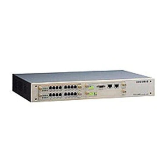
Components of SMG-3200 This section explains each component and function of the SMG-3200 system. Front View of SMG -3200 There are 4 slots for board installation on the front of the SMG-3200 system. Slot Slot For the installation of the MGCB board that controls overall operation of the MGCB SMG-3200 system. -
Page 14: Rear View Of Smg-3200
Rear View of SMG-3200 The rear side of the SMG-3200 system includes a ground terminal, power-in terminal, and power switch. ¶Ground Connector Provides an external ground connection to protect user and system against lightning, static electric charges, spikes, sags, and surges. -
Page 15: Smg-3200 System Specifications
Overview SMG-3200 System Specifications This section describes hardware and software specifications of the SMG-3200 system. Hardware Specifications Feature Processor Memory System VoIP DSP Network Test Port Power Analog Digital Line Capacity VoIP Description MPC860 50MHz Ÿ Boot Flash ROM : 512KB Ÿ... -
Page 16: Software Specifications
Software Specifications Feature VxWorks VoIP Protocol ITU-T H.323-V3 VoIP Codec G.723.1, G.729A, G.711 Ÿ Echo Cancellation (G.165) Ÿ Silence Suppression (VAD, CNG) Ÿ DTMF Detection/Generation(In/Outband) Audio Function Ÿ Selectable A / u law Ÿ Gain/Volume Control Ÿ Dynamic Jitter Control Ÿ... -
Page 17: Voip Network Configuration Using Smg-3200
A VoIP network can be constructed using SMG-3200, PBX, and KTS as the following figure shows. Tandem Gateway Mode The SMG-3200 can be run in the tandem gateway mode. It connects the SMG-3200 to PBX or KTS, and uses the SMG-3200 as a gateway without internal subscribers. -
Page 18: Standalone Gateway Mode
Standalone Gateway Mode The SMG-3200 can be run in the standalone gateway mode. It connects a telephone to an SLC port on the SMG-3200 and uses the system as a VoIP Gateway with internal subscribers. -
Page 19: Chapter 2 System Boards
Chapter System Boards This Chapter describes the types of boards available for the SMG-3200, and the functions and features of each board. Types of Boards There are two types of boards available for the SMG-3200. Common Boards Common boards have to be installed in the SMG-3200 system. They provide important functions such as operational control of the system, and VoIP gateway functions. -
Page 20: Common Boards
Chapter 2 System Boards Common Boards Common boards of the SMG-3200 system include the MGCB board and VOIP board. This section describes the features of each board. MGCB Board MGCB (Media Gateway Control Board) board controls the entire operation of the SMG-3200 system, and is installed in the MGCB system slot. - Page 21 Front Panel and Structure of Board There are E1/PRI, T1 ports, LAN port, RS-232C port, and system status LEDs on the MGCB board. There are 8 DIP switches on the board. MGCB E1/PRI, T1 Port (RJ-45): for E1/PRI, T1 station line connection. LAN Port (RJ-45): for 10/100Mbps Ethernet LAN connection.
- Page 22 Chapter 2 System Boards LED Indicators Color Color Color Color OPER Green LAN TX LAN RX E1 SYNC E1 LOS DIP Switch Switch Switch Switch Switch Default Default Default Default Description Description Description Description LED blinks during system initialization. LED blinks during normal system operation. LED is on when power is normally supplied to system.
- Page 23 If you change the S6,S7,S8 , the SMG-3200 system doesn’t work normally. R2 Board Installation Slot This slot is intended for the installation of the R2 board, a daughter board of the MGCB board. You can find detailed information about the R2 board in the following section.
- Page 24 Each channel is used for PCM data communication at 64Kbps. The PRI (Primary Rate Interface) includes T1, and E1 type stations, but the SMG-3200 only provides E1 type PRI. E1 type PRI offers 30B channels and 1D channel (30B+1D). Each channel provides 64Kbps data communication.
- Page 25 JP1 ~ JP5 Jumper Jumper Jumper Jumper Jumper JP1~JP5 jumpers are intended to specify impedance mapping according to the type of line to be connected to the E1/PRI, T1 board. To connect E1, Close pin #2-3 of all jumpers. To connect T1, Close pin #1-2 of all jumpers.
-
Page 26: Voip Board
The VOIP board performs conversion of the voice data of PSTN into packet data that can be transmitted over IP networks. In other words, it provides H.323 V3-complient VoIP Gateway functions to enable voice communication over the Internet. The VOIP board of the SMG-3200 system comes in a VOIP board with 8 Internet telephone channels. - Page 27 Front Panel and Structure of Board There are LEDs indicating VOIP board status on the front panel of the VOIP board. LED Indicators Color Color Color Color 16CH Green 24CH 32CH VOIP Board With 8 Channels 8CH 24CH LD1 LD3 LD5 LD7 VOIP 16CH 32CH LD2 LD4 LD6 LD8 Description...
- Page 28 Chapter 2 2-10 System Boards (Continued) Color Color Color Color Green Daughter Board Installation Slots Daughter board installation slot is dedicated to the installation of a VOIP_Sub board, the daughter board of a VOIP board. The VOIP board has 3 daughter board installation slots. Therefore, up to 3 VOIP_Sub boards can be installed on the VOIP board.
-
Page 29: Universal Boards
The LOOP (Loop Start Trunk) board provides the local extension trunk interface, and can be installed in the universal slot (US1, US2) of a system. The LOOP board for the SMG-3200 system comes in a LOOP board with 8 ports. It provides a connection to a private branch exchange (PBX), or the local telephone office. -
Page 30: E&M Board
SMG-3200 system and private branch exchange (PBX) or key telephone system (KTS), and can be installed in the universal slot (US1, US2) of a system. The E&M board for the SMG-3200 system comes in an E&M board or 4W E&M board with 8 ports. - Page 31 2-13 The features and functions of the E&M board are as follows. Transformer and impedance matching circuits are built in. It encodes the entered analog signal into the digital signal of the PCM method where the digital signal is decoded into the analog signal on the system through the PCM method. There is separate logic to the control port of the board.
- Page 32 Chapter 2 2-14 System Boards LED Indicators Color Color Color Color Green J1~J8 Jumper Default Default Default Default If the power of the connected system is not – 48V, open the shunt pin of C-B. Description Description Description Description LED is on during each port in use. J1~J8 jumpers are intended to select signaling type for each port of E&M board.
-
Page 33: Slc Board
SMG-3200 system, and can be installed in the universal slot (US1, US2) of a system. The SLC board for the SMG-3200 system comes in a SLC board with 8 ports, and each port provides a connection to an analog telephone. -
Page 34: Chapter 3 Installing The System
Chapter Installing the System This chapter provides SMG-3200 system installation procedures. First, step by step SMG-3200 system installation procedures are presented, and then environment configuration, board installation, and power cable connecting procedures are explained. Procedures on Installing the System Following steps must be taken to install the SMG-3200 system. -
Page 35: Condition Of The Installation Location
Installing the System Condition of the Installation Location SMG-3200 system can be installed in a rack or on a table. To operate the SMG-3200 system securely, you have to find the location that satisfies the conditions described in this chapter before setting up the system. -
Page 36: Grounding Condition
A single contact point must be made to connect if the grounding of all of the exterior supplementary equipment are connected to the system’s grounding. The SMG-3200 grounding conductor should never be connected with the pipe for the interior power wire. -
Page 37: Input Power Condition
In the SMG-3200 input power, an AC 110-240V should be supplied normal alternating current AC power. You should use the consent that supplies normal AC only for the SMG-3200 system. This consent should not be used parallel with other devices. This consent should be located at a safe place to prevent cutting off the power by mistake. -
Page 38: Unpacking The System
Unpacking the System After preparing the place to install the SMG-3200 system and finishing all the preparation work by meeting all the conditions, move the packed SMG-3200 system to the installation location. Unpack the system and check if all the items are in the shipping carton. Basically, there should be the following items in the package. -
Page 39: Installing In A Rack
Installing the System Installing in a Rack SMG-3200 system can be installed in a rack or on a table. Installation of SMG-3200 in a rack enables more convenient usage and management. This section provides procedures for SMG-3200 system installation in a rack. For the case of SMG-3200 system installation on a table, skip this section and refer to the following ‘Connecting Ground Cable’... -
Page 40: Rack Requirements
Rack Requirements Before installation of SMG-3200 system in a rack, you have to prepare a rack that meets the following requirements. Prepare a rack with standard electrical facilities. Ensure that the rack has appropriate ventilators, if it is closed type. A closed type rack should provide at least one ventilator with fan on the side of the rack in order to circulate cool air into the rack. -
Page 41: Installing In A Rack
S M G E 1/ T -3 2 0 1/ P R V O IP 3. By using 4 other screws, install the SMG-3200 unit (with brackets) in a rack. M ed ia Ga te wa S M G -3 2 0... -
Page 42: Connecting Ground Cable
Connecting Ground Cable The protective earth connection to the SMG-3200 is provided via three core mains lead. The earth wire in the mains cord (Green/Yellow) is connected in the factory to the earth terminal within the system. The Earth wire is connected directly to the ground connection on the rear panel of the system. -
Page 43: Installing Boards
System Slots MGCB board, VOIP board, and various Universal boards can be installed in the 4 slots on the front panel of the SMG-3200. For the installation slot of each board refer to the following table. SMG-3200 Media Gateway... -
Page 44: Selecting Boards
Selecting Boards The MGCB board and VOIP board have to be installed for system operation, whereas Universal boards may be installed if desired. The type of Universal board used in the SMG-3200 system is determined by the following conditions. Tandem Gateway Mode In case of using the SMG-3200 in tandem gateway mode, you can install following boards according to the connection method of PBX or KTS. -
Page 45: Setting Jumper And Switch
Chapter 3 3-12 Installing the System Standalone Gateway Mode In case of using the SMG-3200 in standalone gateway mode, you can install only SLC board in Universal slots. MGCB Slot MGCB Slot VOIP VOIP Slot MGCB MGCB Slot Slot VOIP... -
Page 46: Installing Daughter Boards
To use the TYPE II-Standard signaling, Close pin A and O. E1/PRI, T1 Board There are S1 and S2 switches and JP1~JP5 jumpers on the E1/PRI, T1 board. All of these switches and jumpers are to select the kind of station line to be connected to the E1/PRI, T1 board. Prior to the installation of the E1/PRI, T1 board onto the MGCB board, set switches and jumpers according to following directions. - Page 47 Chapter 3 3-14 Installing the System MGCB Board On the MGCB board, the R2 board or E1/PRI, T1 board can be installed. To add 8 channel R2 signaling, install a R2 board. Install the R2 board. To connect to E1/PRI, T1 line Install an E1/PRI, T1 board.
- Page 48 VOIP Board On the VOIP board, up to 3 VOIP_Sub boards can be installed. Since each VOIP_Sub board provides 8 VoIP channels, as a result, a maximum of 24 additional VoIP channels can be installed on the VOIP board. Although installing VOIP_Sub board on the VOIP board is the same as that of the MGCB board, you have to be sure of the location of the VOIP_Sub board for installation.
-
Page 49: Installing Board In A Slot
3-16 Installing the System Installing Board in a Slot Install a board in the slot of the SMG-3200 system, after procedures for daughter board installation is completed. When installing the board, keep the followings in mind. The high voltage static-electric charge is easily accumulated in a human body. Deal with the board after removing all the accumulated electric charge by touching any equipment’s device or... - Page 50 3-17 3. Carefully fit the board into the slot following the guardrails on both sides. 4. Press the center of the front panel of the board so that the board can be completely fit into the connector on the back-plane board. 5.
-
Page 51: Connecting Cables
Pin Name. 1. To connect the SMG-3200 and PBX or KTS with general trunk, connect one end of a RJ-11 cable to the SLC port of the SMG-3200, and the other end to the LOOP port of the PBX or KTS. - Page 52 3. To connect the SMG-3200 and PBX or KTS with E&M line, connect one end of a RJ-11 cable to the E&M port of the SMG-3200, and the other end to the E&M port of the PBX or KTS. At this time, connect E line of one and M line of the other, and connect M line of one and E line of the other.
- Page 53 Installing the System 5. To connect the SMG-3200 and analog terminal such as analog telephone or FAX machine, connect one end of RJ-11 cable to SLC port of the SMG-3200, and the other end to the port of analog terminal.
-
Page 54: Attaching Ferrite Cores
Connecting Power Cable Before connecting the power cable to the SMG-3200, you have to be aware of the following guidelines. Do not connect other equipment to the AC outlet connected to the system to avoid malfunction or fire of the system due to electrical noise and low voltage. -
Page 55: Chapter 4 Configuring The System
Chapter Configuring the System This chapter describes procedures for the configuration of the SMG-3200 operating environment with console terminal as well as the login procedure in console terminal. Setting up the Terminal Terminal setup methods differ according to terminal types and operating system. In this manual, we will using an example of how to use the hyper terminal on a PC running with a Windows 98 operation system. - Page 56 6. Next, the user will the <COMx Properties> window appears, where the user can configure various options for the selected COM port. Configure each item as shown in the following and click [OK]. 7. Next, a new hyper terminal where the user can set up the SMG-3200 by using console commands will pop up.
-
Page 57: Starting Smg-3200
This section describes the login procedure using CLI, after turning on SMG-3200. Turning on While the hyper terminal window is on the screen, turn on the SMG-3200 with the power button in the rear of the system. After the system turn on, system initialization proceeds approximately 60 seconds. The system POST (Power On Self Test) will be executed and the factory-preset configuration data will be loaded and shown on the terminal. -
Page 58: Logging In
Chapter 4 Configuring the System Logging in 1. After the SMG-3200 boots up, the login prompt will show the following. SMG3200 Login: 2. Type ‘ smg3200’ at the login prompt and press [Enter]. SMG3200 Login: smg3200 3. Type password at ‘Password:’ and press [Enter]. When logging in for the very first time, enter ‘smg3200v1’. - Page 59 5. Press [Enter] to display the SMG3200 login prompt. SMG3200:165.213.81.230>...
-
Page 60: Configuring The Operating Environment
To operate the SMG-3200, only the fundamental information configuration is required, and the detailed operation environment configuration is configured automatically by using default values. The following 3 configurations are necessary for the operation of the SMG-3200. Other than these configurations, additional operation environment configurations are not normally used. - Page 61 - IP address of default gateway Option Automatic Configuration To set up TCP/IP information automatically using a DHCP server, configure the SMG-3200 as a DHCP client using the following directions. 1. At the SMG-3200 prompt, type ‘sysmenu’ and press [Enter].
- Page 62 Option Manual Configuration Referring to the following directions, specify static IP address, subnet mask, and IP address of default gateway for the SMG-3200. 1. At the SMG-3200 prompt, type ‘sysmenu’ and press [Enter]. SMG3200:165.213.81.230> sysmenu Items DHCP Client Set Class ID Value [ - :Null, .
- Page 63 | MAC Address(Read Only) +---+----------------------+-----------------------------+ Change Network Configuration? (y: Yes, n: No) -> y y y y 4. The following message is displayed. Input the IP address of the SMG-3200 and press [Enter]. IP Address (dot form): 165.213.81.230 -> 165.213.81.230 Value 165.213.81.230...
- Page 64 5. Input the IP address of default gateway and press [Enter]. Gateway Address (dot form): 165.213.81.1 -> 165.213.81.1 6. Input the subnet mask for the IP address of the SMG-3200 and press [Enter]. Netmask(dot form): 255.255.255.0 -> 255.255.255.0 7. TOS (Type Of Service) value is used to determine the priority of voice packets transmitted from the SMG-3200 on the network, which enables the network to provide better QOS (Quality Of Service).
-
Page 65: Configuring The System Operation Mode
Setting up Gateway Operation Mode SMG-3200 gateway operates in either of the following 2 operation modes. ☞ Tandem Gateway : SMG-3200 communicates with PBX or KTS over PSTN trunk without ☞ Standalone Gateway : SMG-3200 communicates with analog telephone with PSTN trunk Configure gateway operation mode of SMG-3200 referring to the following directions. - Page 66 Chapter 4 4-12 Configuring the System 1. At the SMG-3200 prompt, type ‘pstnmenu’ and press [Enter]. SMG3200:165.213.81.230> pstnmenu 2. <PSTN Configuration Menu> screen is displayed. Type ‘0’ and press [Enter]. <<<<< PSTN Configuration Menu >>>>> [0] Gateway Operation Mode [1] PSTN Rerouting Insert Digit...
- Page 67 3. To configure the gateway operation mode of the SMG-3200, type ‘0’ and press [Enter]. < < < < < Gateway Operation Mode > >> > > +----+-----------------------+----------------+-------------+ | No Items +----+-----------------------+----------------+-------------+ Gateway Operation Mode PSTN Inbound LCR Option +----+-----------------------+----------------+-------------+ <<...
- Page 68 Setting up PCM Type PCM (Pulse Code Modulation) is the most frequently used analog-to-digital encoding (A/D conversion technique to convert analog voice into digital signal). SMG-3200 provides 2 PCM types, which are A-law and U-law. ☞ A-law : A-law is an ITU-T (International Telecommunication Union) standard for analog-to- digital conversion in PCM.
- Page 69 1. In the <PSTN Configuration Menu> screen, type ‘2’ and press [Enter]. <<<<< PSTN Configuration Menu >>>>> [0] Gateway Operation Mode [1] PSTN Rerouting Insert Digit [2] PCM Method [3] Dial Method [4] SLC Signal [5] Trunk Signal [6] Call Control Method [7] Ring Cadence [8] System Tone Cadence [9] CO Tone Cadence...
- Page 70 6. Message asking if you want to save the changed configuration in flash memory is displayed. Type ‘y’ and press [Enter]. # PSTN Configuration has changed. Save? (y: Yes, n: No) -> y 7. Changed data is saved in flash memory, and you are returned to the initial screen of the SMG-3200 CLI interface.
-
Page 71: Configuring The Voip
Configuring the VoIP This section describes the procedures for the SMG-3200 VoIP configuration. The SMG-3200 VoIP configuration procedure is determined by the Gatekeeper service that translates terminal aliases such as telephone number in E.164 format, e-mail address, and H.323 ID into an IP address. - Page 72 +-----+--------------------+-----+--------------------+ +-----+--------------------+-----+--------------------+ Configuration Item Number: 1 1 1 1 5. Input IP address of opposite VoIP equipment to be connected to the SMG-3200 and press [Enter]. IP Address (dot form): 0.0.0.0 -> 6. To register the IP address of other VoIP equipment, repeat steps 4 ~ 5.
- Page 73 7. After VoIP table creation is completed, type ‘.’ and press [Enter]. Configuration Item Number: . 8. To close current screen, type ‘.’ and press [Enter]. IP Table Index Number(Range: 0 ~ 31): . 9. After returning to the <VoIP Configuration Menu> screen. Type ‘8’ and press [Enter]. <<<<<...
- Page 74 Option When using Gatekeeper Configure Gatekeeper information according to the following directions. 1. At the SMG-3200 prompt, type ‘voipmenu’ and press [Enter]. SMG3200:165.213.81.230> voipmenu 2. <VoIP Configuration Menu> screen is displayed. Type ‘2’ and press [Enter]. <<<<< VoIP Configuration Menu >>>>>...
- Page 75 3. <VoIP Gatekeeper Option> screen is displayed. Type ‘0’ and press [Enter]. < < < < < VoIP Gatekeeper Option > > >> > +--+--------------------+-------------------+---------------+ | No | Items +--+--------------------+-------------------+---------------+ | 0 | Gatekeeper Connection | Gatekeeper Status | 1 | RAS Method | 2 | Registration Type | 3 | Gatekeeper Type | 4 | GW Routing In GK mode...
- Page 76 8. Input alias name (host name) of gatekeeper and press [Enter]. Gatekeeper Alias Name : Gatekeeper -> Gatekeeper1 9. To specify H.323 ID of the SMG-3200, type ‘9’ and press [Enter]. Configuration Item Number: 9 10. Input H.323 ID of the SMG-3200 for login and press [Enter].
-
Page 77: Chapter 5 Cli (Command Line Interface)
Menu Configuration The CLI menu of the SMG-3200 consists of 6 main menus. Each menu has a number of submenus, except for ‘help’ and ‘quit’ menus. Main Menu... - Page 78 Chapter 5 CLI (Command Line Interface) [3]VoIP Routing Table [4]VoIP Caller ID Table [5]VoIP Remote IP Table [6]VoIP Remote IP Status [7] Save & Exit [8] Exit clicmd clicmd cdrhelp date dbfilehelp optionhelp settime quit...
-
Page 79: Using Menus
Make sure that you familiarize yourself with the following instructions on the CLI Menus of the SMG-3200. Selecting the Main Menu To select the Main Menu from prompt on the SMG-3200 main screen, type in the name of the desired menu. For example, type ‘sysmenu’ and press [Enter] to select sysmenu. Selecting a Submenu To select a submenu, type the number of the desired submenu. -
Page 80: System Configuration Menu
CLI (Command Line Interface) System Configuration Menu You can set overall system functions, such as IP address and login password, of the SMG-3200 from the System Configuration Menu. You can also view values of parameters such as system version information. -
Page 81: Dhcp Client Setting
[0] DHCP Client Setting Function You can set the SMG-3200 as a DHCP client. By doing so, the DHCP server automatically allocates an IP address for the SMG-3200. After the setup, you must restart the system to implement the change. -
Page 82: Network Configuration
Chapter 5 CLI (Command Line Interface) [1] Network Configuration Function Users can set the network configuration such as IP address for the SMG-3200, default gateway address and subnet mask. After setup, you must restart the system to implement the change. Procedure 1. - Page 83 Range:0x00 ~ 0xFF, Default:0x00 TOS Value (Default: 0x00): 0x00 -> When you set TOS for the SMG-3200, you must set router to support the TOS. You can configure TOS values, if necessary, to process QoS (Quality of Service) regardless of whether using a DHCP server or not.
- Page 84 Chapter 5 CLI (Command Line Interface) [2] Login ID Configuration Function You can change the login name and password of CLI. Default Login Name Value Login Passwd smg3200v1 Procedure 1. In the <System Configuration Menu> screen, type ‘2’, and press [Enter]. <...
-
Page 85: System Upgrade
You can view the system upgrade information, or change the program of the DSP chip for VoIP and the operation program for the SMG-3200 using TFTP or FTP. Changes are stored in the system’s flash memory and will be implemented when the system is rebooted. - Page 86 Chapter 5 5-10 CLI (Command Line Interface) 2. To upgrade the system software, type ‘y’, and press [Enter]. Upgrade This System? (y: Yes, n: No) -> y 3. Select an upgrade method and press [Enter]. Upgrade Method (1: TFTP, 2: FTP) -> 4.
-
Page 87: Display Package Information
Saved Program File Count : Number of program files stored in flash Upgrade Status : Status of the latest upgraded system program. EMS: Indicates whether EMS (Element Management System), the GUI Items memory. maintenance tool for the SMG-3200, is enabled. 5-11 Value BootROM ver 1.1 3200V2.2:020307 3200V2.2:020307... -
Page 88: Default Db Setting
5-12 CLI (Command Line Interface) [5] Default DB Setting Function You can set all values of each variable in the SMG-3200 to default values, by database type. Procedure 1. In the <System Configuration Menu> screen, type ‘5’, and press [Enter]. -
Page 89: Restart System
[6] Restart System Function When you execute the system restart command the system will restart provided that the value of Upgrade Status on the 4) Display Package Information menu is ‘SUCCESS’. If the value is ‘Fail’ or ‘Loading’, the system will not restart and a warning message will appear. -
Page 90: Pstn Configuration Menu
In the PSTN Configuration Menu, you can set the PSTN interface that is required to connect to the PSTN trunk line. You can also view the values of parameters. At the SMG-3200 prompt of the main screen, type ‘pstnmenu’ and press [Enter]. The following PSTN Configuration Menu screen will be displayed. - Page 91 The following is an overview of the 17 submenus found in the PSTN Configuration Menu. Menu Menu Menu Menu Gateway Operation Mode PSTN Rerouting Insert Digit PCM Method Dial Method SLC Signal Trunk Signal Call Control Method Ring Cadence System Tone Cadence CO Tone Cadence Gain Control Diagnosis...
-
Page 92: Gateway Operation Mode
The SMG-3200 operates in either of the following modes. In this menu you can configure the operation mode of the SMG-3200. - Tandem Gateway : You can connect the SMG-3200 to PBX or KTS, and use the system as a gateway without internal subscribers. - Page 93 | 17 | +--+-----------+-------++---+----------+-------+ Configuration Item Number:0 2. To change the operation mode of the SMG-3200, type ‘0’ in the above screen, and press [Enter]. Configuration Item Number: 0 3. To change the operation mode to Tandem Gateway or Standalone, press ‘0’ or ‘1’...
- Page 94 Maxdigit count. This value analyzes dialing digits to decide the termination of dialing. - Inbound Prefix: the prefix pattern of dialing digits coming into SMG-3200 - Max Digit Count: The maximum number of dialing digits coming into SMG-3200 with the designated prefix.
-
Page 95: Pstn Rerouting Insert Digit
IP network being busy or disconnected or in error. At the time of PSTN rerouting, an access code is required for PABX or KTS connected to SMG-3200 to access the PSTN trunk line depending on the environment of the operating site. This access code can be specified. -
Page 96: Pcm Method
PCM (Pulse Code Modulation) is the most frequently used analog-to-digital encoding (A/D conversion technique to convert analog voice into digital signal). SMG-3200 provides 2 PCM types, which are A-law and μ-law. In this menu, PCM type can be changed. Procedure 1. -
Page 97: Dial Method
[3] Dial Method Function You can set the digit transmission method and its options on the trunk connected to a PSTN interface. MFC (DTMF) : The digit transmission method that is used to send pressed Dial Pulse : The digit transmission method that is used to send dialed numbers on R2MFC : The digit transmission method that is used in digital trunks such as E1 Procedure 1. - Page 98 Sets whether you accept (ON) or not (OFF) Called Status Response the caller’s request for call status. Must be specified when the SMG-3200 is Calling Extension used in Standalone mode, but it is currently Response not in service.
-
Page 99: Slc Signal
[4] SLC Signal Function You can set the signal type of the SLC interface. Procedure 1. In the <PSTN Configuration Menu> screen, type ‘4’, and press [Enter]. < < < < < SLI Signal > > > > > +---+-------------------+------+---------+-------+ | No | SLI Signal Timer +---+-------------------+------+---------+-------+ +---+-------------------+------+---------+-------+... -
Page 100: Trunk Signal
Chapter 5 5-24 CLI (Command Line Interface) [5] Trunk Signal Function You can set the signal type for analog and digital trunk. Procedure 1. In the <PSTN Configuration Menu> screen, type ‘5’, and press [Enter]. < < < < < Trunk Signal >> > > > +---+-------------------+---------------+---------+ | No | +---+-------------------+---------------+---------+... - Page 101 Description Selects the signal type for trunk interface. 0. Immediate 1. Wink 2. Delay Input ‘#’ to terminate dialing when SMG-3200 is making a dialing through trunk line to PABX or KTS. Off: does not input ‘#’ On: inputs ‘#’...
- Page 102 E1 CRC4 signal frame without encoding Enable: sends the CRC bit to synchronization signal frame with encoding SMG-3200 supports a PRI protocol of EU and PRI Type KOR type in the current version. Sets the PRI channel mode. Exclusive Mode: sets the channel previously and makes a call.
- Page 103 (Continued) Item Item Item Item The time elapsed for the process of transmission being abandoned when a hook off signal is not Noring Time maintained from the moment a hook off is detected and responded. Typed number x 1sec is the actual time.
-
Page 104: Call Control Method
Chapter 5 5-28 CLI (Command Line Interface) [6] Call Control Method Function You can set the signal type required to process a call. Procedure 1. In the <PSTN Configuration Menu> screen, type ‘6’, and press [Enter]. < < < < < Call Control Method > > > > > +---+------------------+------+---------+---------+ | No | +---+------------------+------+---------+---------+... - Page 105 3. Specify a value referring to the following table, and press [Enter]. Item Item Item Item First Digit Time Inter Digit Time Loop OK Time OK Release Time Description Description Description Description The time elapsed to receive the first digit after hook off.
-
Page 106: Ring Cadence
Chapter 5 5-30 CLI (Command Line Interface) [7] Ring Cadence Function You can distinguish the ring type by setting the ring cadence (interval between rings). Sets the cadence in units of 100msec. Procedure 1. In the <PSTN Configuration Menu> screen, type ‘7’, and press [Enter]. <... - Page 107 Set the cadence for the selected ring type, and press [Enter]. Typed number x 100msec is the actual time. Item Item Item in Detail Item in Detail Item Item Item in Detail Item in Detail SLI Ring 1st on Time SLI Ring 1st off Time SLI Ring 2nd on Time SLI Ring 2nd off Time...
-
Page 108: System Tone Cadence
CLI (Command Line Interface) [8] System Tone Cadence Function You can set the tone cadence that is sent by the SMG-3200. Sets the tone cadence by tone type in units of 50msec. Procedure 1. In the <PSTN Configuration Menu> screen, type ‘8’, and press [Enter]. - Page 109 (Continued) Item Item Item in Detail Item in Detail Item Item Item in Detail Item in Detail BUSY 1 on Time BUSY 1 off Time Busy Tone BUSY 2 on Time BUSY 2 off Time TRANSFER 1 TRANSFER 1 off Time Transfer Tone TRANSFER 2...
-
Page 110: Co Tone Cadence
Chapter 5 5-34 CLI (Command Line Interface) [9] CO Tone Cadence Function You can set CO tone cadence to identify tones coming from a CO when the SMG- 3200 is connected to a CO line. The tone cadence can be set to units of 50msec by tone type. - Page 111 3. Set the CO tone cadence referring to the following table, and press [Enter]. Typed number x 50msec is the actual time. Item Item Item in Detail Item in Detail Item Item Item in Detail Item in Detail BUSY CO TONE on Time BUSY CO TONE Busy...
-
Page 112: Gain Control
Chapter 5 5-36 CLI (Command Line Interface) [10] Gain Control Function You can adjust call quality (gain control) depending on the connection type, i.e. analog telephone, analog trunk or digital trunk line. Each gain is set in units of dB. Procedure 1. - Page 113 3. Set value of gain referring to the following table, and press [Enter]. Item Item Item Item Specifies the call quality that transmits from TX to RX of analog telephone. Specifies the call quality that transmits from TX of ATRK analog telephone to RX of analog trunk.
-
Page 114: Diagnosis
CLI (Command Line Interface) [11] Diagnosis Function You can set a regular interval to diagnose the PSTN interface of the SMG-3200. Setting it to ‘0’ it bypasses the diagnosis. You can set the interval at units of 1sec by the test type. -
Page 115: Mmc Port Block/Unblock
[12] MMC Port Block/UnBlock Function You can set Block/UnBlock on each port of the system. ‘Block’ indicates ‘disabled to use’ and ‘UnBlock’ indicates ‘enabled to use’. Procedure 1. In the <PSTN Configuration Menu> screen, type ‘12’, and press [Enter]. < < < < < MMC Port Block/UnBlock >>> >> +----+--------------------------------------------+ | Port | | No. - Page 116 Chapter 5 5-40 CLI (Command Line Interface) 2. Type ‘1’ to block or ‘2’ to unblock, and press [Enter]. Select Block or UnBlock (1: Block, 2: UnBlock) -> 3. Input the slot number for the port specified to be unblocked, and press [Enter]. Blocking Slot Number: (0: VoIP, 1: USL1, 2: USL2, 3: D-TRK) 4.
-
Page 117: Display Slot Configuration
[13] Display Slot Configuration Function Displays type of cards that are installed on each slot of the system. Procedure 1. In the <PSTN Configuration Menu> screen, type ‘13’, and press [Enter]. < < < < < Display Slot Configuration >>> > +-----------+------------------+------------------+ +-----------+------------------+------------------+ | 0( VoIP ) -
Page 118: Display Port Status
Chapter 5 5-42 CLI (Command Line Interface) [14] Display Port Status Function You can view the status of each port installed in the system slots. Procedure 1. In the <PSTN Configuration Menu> screen, type ‘14’, and press [Enter]. 2. When the following message appears, input the slot number to display, and press [Enter]. - Page 119 5-43 MMC Block : Indicates the operational status of the related port. ‘UnBlock’ indicates ‘enabled to use’, ‘Block’ indicates ‘disabled to use’. Call State : Indicates the internal process status of a call. This value is used to trace the call processing status. Opp.
-
Page 120: Save & Exit
Chapter 5 5-44 CLI (Command Line Interface) [15] Save & Exit Function After saving changes, it closes the <PSTN Configuration Menu> screen, and returns to the main menu screen. Procedure In the <PSTN Configuration Menu> screen, type ‘15’, and press [Enter]. [16] Exit Function Without saving changes, it closes the <PSTN Configuration Menu>... -
Page 121: Voip Configuration Menu
VoIP Configuration Menu In the VoIP Configuration Menu, you can control the IP interface that connects to the SMG-3200. You can also set IP routing information together with VoIP features. At the prompt on the startup screen, type ‘VoIPmenu’ and press [Enter]. The following screen will be displayed. -
Page 122: Voip General Option
Chapter 5 5-46 CLI (Command Line Interface) [0] VoIP General Option Function You can set general options for VoIP services. Procedure 1. In the <VoIP Configuration Menu> screen, type ‘0’, and press [Enter]. < < < < < VoIP General Option > > > > > +---+------------------------+--------+---------+ | No +---+------------------------+--------+---------+... - Page 123 GWID, it is the ID information that is sent to the other party. When sending a VoIP call via IP network, it selects the Caller ID type that is sent from the SMG-3200 to recipients. 0. GWID: Uses Gateway ID number.
- Page 124 +1) can be used. Status Sets the status monitoring period between Samsung’s Monitori VoIP Gateways. It is only to be used when the SMG-3200 ng Period is connected to Samsung’s VoIP Gateway. Max. Fax Sets the max allowable number of Internet fax channels Service with the SMG-3200.
-
Page 125: Voip Dsp Option
[1] VoIP DSP Option Function You can set DSP (Digital Signal Processing) options for VoIP services. Procedure 1. In the <VoIP Configuration Menu> screen, type ‘1’, and press [Enter]. < < < < < VoIP DSP Option > > > > > +---+---------------------+----------+----------+ | No | +---+---------------------+----------+----------+... - Page 126 Chapter 5 5-50 CLI (Command Line Interface) 3. Set the values for the selected item referring to the following table, and press [Enter]. Item Selects VoIP Codec. 1. G.711 (64K) Audio Codec 2. G.723.1 (6.3K) 3. G.729a (8K) 4. G.729 (8K) Echo Cancellation is the function to remove echo that Echo is generated by voice reflection on Packet Delay and...
- Page 127 (Continued) Item Sets the loss limit on voice packets received through RTP. RTP Loss Limit communication, it is used as a basic index for network error. RTP Loss Check Sets the RTP Loss check period. Period When the RTP Delay Limit or RTP Loss Limit is RTP OverLimit exceeded, it sets the standard accumulated frequency Count...
-
Page 128: Voip Gatekeeper Option
5-52 CLI (Command Line Interface) [2] VoIP Gatekeeper Option Function You can set information required for Gatekeeper connection when the SMG-3200 is to be connected to Gatekeeper. Procedure 1. In the <VoIP Configuration Menu> screen, type ‘2’, and press [Enter]. - Page 129 Gatekeeper. The types include E.164 ID Type of Gateway mode and Caller ID in the Caller ID Table. Specifies the manufacturer of Gatekeeper. SIGK : Select if Samsung Internet Gatekeeper is to be Gatekeeper connected.. Type Other GK : Select if other company’s Gatekeeper is to be connected.
- Page 130 0. Alternative GK : Connects to the alternative Down Option 1. PSTN : Uses PSTN rerouting. Gateway Name Sets H.323 ID to be registered as ID of SMG-3200 H.323 ID with Gatekeeper. Gateway Name Sets E.164 to be registered as ID of SMG-3200 with E.164...
-
Page 131: Voip Routing Table
| 63 | +----+-----------+--------+--------+-----------+-------------+----------+-----+ 3. Input the routing table number to be changed, and press [Enter]. It sets the way of handling dialing digits sent to IP Network though SMG-3200. Configuration Item Number: |Acc Code|Acc Code| Insert |IPTable(0 31)| IP Table | GK |... - Page 132 Chapter 5 5-56 CLI (Command Line Interface) 4. Set the values for the selected item referring to the following table, and press [Enter]. Access Code Acc Code Length Acc Code Del-Len Insert Digit IP Table Index1 IP Table Index2 IP Table Start Point GK Use 5.
- Page 133 (Continued) <<<<< VoIP Outbound Routing Table >>>>> +----+-----------+--------+--------+-----------+-------------+----------+-----+ |Acc Code|Acc Code| Insert | No |Access Code| Length | Del-Len| +----+-----------+--------+--------+-----------+------+------+----------+-----+ | 0 | | 1 | | 2 | | 3 | | 4 | | 5 | | 6 | | 7 | | 8 | | 9 |...
- Page 134 Chapter 5 5-58 CLI (Command Line Interface) 7. Set the values for the selected item referring to the following table, and press [Enter]. Access Code Acc Code Length Acc Code Del-Len Insert Digit Item Item Item Item The Prefix pattern of the incoming dialing digits. The maximum length of Access Code digit is 16.
-
Page 135: Voip Caller Id Table
You can set the Caller ID when sending a call through IP Network. Caller ID can be set separately according to the PSTN ports of SMG-3200. To use this feature, the second item of [0] VoIP General Option, Caller ID Type, must be set to Caller ID Table. -
Page 136: Voip Remote Ip Table
Chapter 5 5-60 CLI (Command Line Interface) [5] VoIP Remote IP Table Function More than one IP address must be specified in the VoIP IP Table that is set by the VoIP Routing Table for VoIP outgoing call services. The VoIP IP Table is the table containing the IP address information of another party’s VoIP device, which will be connected with access codes. - Page 137 5-61 4. Input the table number to set IP addresses, and press [Enter]. Configuration Item Number: 5. When the following message appears, type in an IP address and press [Enter]. IP Address (dot form): 0.0.0.0 ->...
-
Page 138: Voip Remote Ip Status
Chapter 5 5-62 CLI (Command Line Interface) [6] VoIP Remote IP Status Function You can display the status of each IP address in the VoIP IP Table. With the SMG- 3200 Gateway function of monitoring status, this menu provides accurate status information. - Page 139 Unless the value of 14 Status Monitoring Period, is ‘0’, you get the exact information. This feature can be used only when SMG-3200 is connected to Samsung Gateway. 4. The following status information may be displayed. Idle : Indicates ‘normal status’ to access VoIP outgoing call services.
-
Page 140: Save & Exit
Chapter 5 5-64 CLI (Command Line Interface) [7] Save & Exit Function After saving changes, it closes the <VoIP Configuration Menu> screen, and returns to the main menu screen. Procedure In the <VoIP Configuration Menu> screen, type ‘7’, and press [Enter]. [8] Exit Function Without saving changes, it closes the <VoIP Configuration Menu>... -
Page 141: Cli Command Menu
The CLI Command Menu displays the list of CLI commands, which SMG-3200 system administrators can use, and provides simple directions. At the SMG-3200 prompt, type 'clicmd,' and press [Enter]. Then, the screen displays a list of simple descriptions of available CLI commands as follows: <<<<<... - Page 142 Function It displays the list of CLI commands that the user can use to operate the system. Procedure Type ‘clicmd’ at the SMG-3200 prompt, and press [Enter]. Then, the following CLI command list is displayed on the screen. SMG3200:165.213.81.230> clicmd...
- Page 143 CDR format, please see "Chapter 7 Using the CDR (Call Detail Record)." Procedure At the SMG-3200 prompt, type 'cdrhelp,' and press [Enter]. Then, the following CLI command list related to CDR information is displayed on the screen. SMG3200:165.213.81.230> cdrhelp...
- Page 144 Function It displays the CDR information regarding the currently connected call. Procedure If you want to see the CDR information regarding the currently connected call, type 'cdrlist' at the SMG-3200 prompt, and press [Enter]. SMG3200:165.213.81.230> cdrlist 13. DVI: 1/1/2002 14:23:23 14:23:32 201 201 165.213.81.230 40 ffff 32 value = 2 = 0x2 SMG3200:165.213.81.230>...
- Page 145 CDR port as the default port. It will revert the system back to the initial setting. Procedure If you want to delete all CDR information, type 'CDRclear' at the SMG-3200 prompt, and press [Enter]. SMG3200:165.213.81.230> CDRclear >>>[CDR] Turn Off CDR Output on TCP Link...
- Page 146 UDP Port UDP IP Address Procedure you want to see the setting of the CDR-related options, type 'CDRsetlist' at the SMG-3200 prompt, and press [Enter]. SMG3200:165.213.81.230> CDRsetlist >>>[CDR] Turn On CDR Output on TCP Link >>>[CDR] TCP Port: 8200 >>>[CDR] Turn Off CDR Output on UDP Link >>>[CDR] UDP Port: Unknown...
- Page 147 Default [CDR] TCP Port 8200 Procedure At the SMG-3200 prompt, type 'CDRtcpport' and a space, and type the TCP port for displaying the CDR information, and then press [Enter]. For example, if you want to set the TCP port for displaying the CDR information...
- Page 148 Set the UDP IP address and UDP port for the UDP Link that will display the CDR output information. Procedure In the SMG-3200 prompt, type 'CDRudpport' and a space, and type the UDP IP address and port for displaying the CDR information, and then press [Enter].
- Page 149 TCP Link is not generated. Basically, the CDR TCP Link is turned Off. Procedure If you want to inactivate the current TCP CDR output Link, type 'Offcdrtcp' at the SMG-3200 prompt, and press [Enter]. SMG400:165.213.81.230> Offcdrtcp >>>[CDR] Turn Off CDR Output on TCP Link Goodvalue = 0 = 0x0 SMG3200:165.213.81.230>...
- Page 150 UDP Link is not generated. Basically, the CDR UDP Link is turned Off. Procedure If you want to inactivate the current UDP CDR output Link, type 'Offcdrudp' at the SMG-3200 prompt, and press [Enter]. SMG3200:165.213.81.230> Offcdrudp >>>[CDR] Turn Off CDR Output on UDP Link Goodvalue = 0 = 0x0 SMG3200:165.213.81.230>...
- Page 151 Basically, the CDR TCP link output is turned Off. Procedure 1. If you want to display the CDR information on the TCP Link, type 'Oncdrtcp' at the SMG-3200 prompt, and press [Enter]. SMG3200:165.213.81.230> Oncdrtcp >>>[CDR] Turn On CDR Output on TCP Link >>>[CDR] TCP Port(8500)
- Page 152 Defaults, and users must set them. Procedure 1. If you want to display the CDR information on the UDP Link, type 'Oncdrudp' at the SMG-3200 prompt, and press [Enter]. SMG3200:165.213.81.230> Oncdrudp >>>[CDR] Turn On CDR Output on UDP Link >>>[CDR] UDP IP Address = 165.213.87.85...
- Page 153 Function It displays the current system time in the 'day of the week month day hour:minute:second year' format. Procedure Type 'date' at the SMG-3200 prompt, and press [Enter]. SMG3200:165.213.81.230> date >>> Date: Thu Feb 21 10:32:12 2002 value = 1 = 0x1 SMG3200:165.213.81.230>...
- Page 154 The system information file is an ASCII file. Procedure At the SMG-3200 prompt, type 'dbfilehelp,' and press [Enter]. Then the following DB-related CLI command list is displayed on the screen. SMG3200:165.213.81.230> dbfilehelp dbfilehelp getdefdb "filename"...
- Page 155 It saves the default DB value of the current system in a file. Procedure At the SMG-3200 prompt, type 'getdefdb' and a space, and type the file name to save, and press [Enter]. Then, the default DB backup file is created. The file name must be in quotation marks ("").
- Page 156 It saves the DB value currently set for the system in a file. Procedure At the SMG-3200 prompt, type 'getdb' and a space, and type the file name to save, and press [Enter]. Then, the system DB backup file is created. The file name must be in quotation marks ("").
- Page 157 DB for the system. Procedure At the SMG-3200 prompt, type 'putdb' and a space, and type the file name of the DB to save in the system, and press [Enter]. Then, the system DB is saved as the applicable DB value.
- Page 158 For detailed description of system information file configuration, please see "Appendix B. System Information File Configuration." Procedure At the SMG-3200 prompt, type 'dump' and a space, and type the name of the file to display, and press enter [Enter]. Then, the file is displayed on the console screen.
- Page 159 MG3200:165.213.81.230> ls <- Check system information file. DB.TXT value = 0 = 0x0 SMG3200:165.213.81.230> dump "db.txt" <- Print the system information file on the screen. system_db() sys.dhcp() sys.dhcp.client = 0 ; def(0) min(0) max(1) (0)no, (1)yes sys.dhcp.classid = ; def() sys.network_parameter() sys.network.my_ipaddr = 165.213.81.230 ;...
- Page 160 It is used to read the system information file from the console and save it in a file. Procedure 1. At the SMG-3200 prompt, type 'load' and a space, and type the name of the file for entering characters, and press [Enter]. Then, the prompt on the next line will blink.
- Page 161 SMG3200:165.213.81.230> ls <- Command used to check the file value = 0 = 0x0 SMG3200:165.213.81.230> load "db.txt" <- The system information is saved in db.txt file. system_db() <- Enter the system information. sys.dhcp() sys.dhcp.client = 0 ; sys.dhcp.classid = ; <- Enter '.' in the first space to finish.
- Page 162 This command displays short descriptions of CLI commands concerning miscellaneous options that can be set in the system. Procedure At the SMG-3200 prompt, type 'optionhelp,' and press [Enter]. Then, the following CLI command list for setting options is displayed on the screen. SMG3200:165.213.81.230> optionhelp...
- Page 163 800 Off (tandem mode) On (Standalone mode) hot connection Off broadcast function Off loop disconnect check functionOff Procedure Type 'Showoption' at the SMG-3200 prompt, and press [Enter]. SMG3200:165.213.81.230> Showoption 800 : On hot connection : Off broadcast function : Off...
- Page 164 This CLI sets the currently active status, and if the setting needs to be maintained during system booting, it must be saved in the CLI’s pstnmenu. Procedure 1. At the SMG-3200 prompt, type 'Off800,' and press [Enter]. SMG3200:165.213.81.230> Off800 Off 800 option...
- Page 165 2. To maintain this setting during system booting, enter the CLI’s pstnmenu and select item 15 '[15] Save & Exit,' and press [Enter]. SMG3200:165.213.81.230> pstnmenu <<<<< PSTN Configuration Menu >>>>> [0] Gateway Operation Mode [1] PSTN Rerouting Insert Digit [2] PCM Method [3] Dial Method [4] SLI Signal [5] Trunk Signal...
- Page 166 This CLI sets the currently active status, and if the setting needs to be maintained during system booting, it must be saved in the CLI’s pstnmenu. Procedure 1. At the SMG-3200 prompt, type 'On800,' and press [Enter]. SMG3200:165.213.81.230> On800 On 800 option...
- Page 167 2. To maintain this setting during system booting, enter the CLI’s pstnmenu and select item 15 '[15] Save & Exit,' and press [Enter]. SMG3200:165.213.81.230> pstnmenu <<<<< PSTN Configuration Menu >>>>> [0] Gateway Operation Mode [1] PSTN Rerouting Insert Digit [2] PCM Method [3] Dial Method [4] SLI Signal [5] Trunk Signal...
- Page 168 This CLI sets the currently active status, and if the setting needs to be maintained during system booting, it must be saved in the CLI’s pstnmenu. Procedure 1. At the SMG-3200 prompt, type 'Offhotconnection,' and press [Enter]. SMG3200:165.213.81.230> Offhotconnection Off hot connection...
- Page 169 2. To maintain this setting during system booting, enter the CLI’s pstnmenu and select item 15 '[15] Save & Exit,' and press [Enter]. SMG3200:165.213.81.230> pstnmenu <<<<< PSTN Configuration Menu >>>>> [0] Gateway Operation Mode [1] PSTN Rerouting Insert Digit [2] PCM Method [3] Dial Method [4] SLI Signal [5] Trunk Signal...
- Page 170 This CLI sets the currently active status, and if the setting needs to be maintained during system booting, it must be saved in the CLI’s pstnmenu. Procedure 1. At the SMG-3200 prompt, type 'Onhotconnection,' and press [Enter]. SMG3200:165.213.81.230> Onhotconnection On hot connection...
- Page 171 2. To maintain this setting during system booting, enter the CLI’s pstnmenu and select item 15 '[15] Save & Exit,' and press [Enter]. SMG3200:165.213.81.230> pstnmenu <<<<< PSTN Configuration Menu >>>>> [0] Gateway Operation Mode [1] PSTN Rerouting Insert Digit [2] PCM Method [3] Dial Method [4] SLI Signal [5] Trunk Signal...
- Page 172 (default) This CLI sets the currently active status, and if the setting needs to be maintained during system booting, it must be saved in the CLI’s pstnmenu. Procedure 1. At the SMG-3200 prompt, type 'Offbcast,' and press [Enter]. SMG3200:165.213.81.230> Offbcast Off broadcast function...
- Page 173 2. To maintain this setting during system booting, enter the CLI’s pstnmenu and select item 15 '[15] Save & Exit,' and press [Enter]. SMG3200:165.213.81.230> pstnmenu <<<<< PSTN Configuration Menu >>>>> [0] Gateway Operation Mode [1] PSTN Rerouting Insert Digit [2] PCM Method [3] Dial Method [4] SLI Signal [5] Trunk Signal...
- Page 174 It sets the function to connect the speaker through E&M and Loop, and broadcast. If this function is set and a call is tried at the specified phone number, the speaker is connected to the applicable slot and channel of the SMG-3200 system, and can be used for broadcasting.
- Page 175 2. To maintain this setting during system booting, enter the CLI’s pstnmenu and select item 15 '[15] Save & Exit,' and press [Enter]. SMG3200:165.213.81.230> pstnmenu <<<<< PSTN Configuration Menu >>>>> [0] Gateway Operation Mode [1] PSTN Rerouting Insert Digit [2] PCM Method [3] Dial Method [4] SLI Signal [5] Trunk Signal...
- Page 176 This CLI sets the currently active status, and if the setting needs to be maintained during system booting, it must be saved in the CLI’s pstnmenu. Procedure 1. At the SMG-3200 prompt, type 'Offloopcheck,' and press [Enter]. SMG3200:165.213.81.230> Offloopcheck Off Loop Disconnect Check Function...
- Page 177 2. To maintain this setting during system booting, enter the CLI’s pstnmenu and select item 15 '[15] Save & Exit,' and press [Enter]. SMG3200:165.213.81.230> pstnmenu <<<<< PSTN Configuration Menu >>>>> [0] Gateway Operation Mode [1] PSTN Rerouting Insert Digit [2] PCM Method [3] Dial Method [4] SLI Signal [5] Trunk Signal...
- Page 178 In the Loop incoming mode, the Loop checks the disconnect tone periodically to prevent the channel from being tied up. For example, if the SMG-3200 system is in the tandem mode where VoIP enters and then go out with seizing the Loop, the Loop may not be aware that the VoIP part is disconnected, and thereby the Loop and SLC can be tied up.
- Page 179 2. To maintain this setting during system booting, enter the CLI’s pstnmenu and select item 15 '[15] Save & Exit,' and press [Enter]. SMG3200:165.213.81.230> pstnmenu <<<<< PSTN Configuration Menu >>>>> [0] Gateway Operation Mode [1] PSTN Rerouting Insert Digit [2] PCM Method [3] Dial Method [4] SLI Signal [5] Trunk Signal...
- Page 180 Default ISP type Procedure 1. At the SMG-3200 prompt, type 'Setisptype' and enter the desired ISP type, and press [Enter]. For example, if you want to set a Samsung Network company as the ISP type (1), type 'Setisptype 1' on the screen, and press [Enter].
- Page 181 2. To maintain this setting during system booting, enter the CLI’s VoIPmenu and select item 7 '[7] Save & Exit,' and press [Enter]. SMG3200:165.213.81.230> VoIPmenu <<<<< VoIP Configuration Menu >>>>> [0] VoIP General Option [1] VoIP DSP Option [2] VoIP Gatekeeper Option [3] VoIP Routing Table [4] VoIP Caller ID Table [5] VoIP Remote IP Table...
- Page 182 (The error is about 5 seconds per day.) Therefore, accurate time must be maintained by setting time during system booting or on a periodical basis. Procedure At the SMG-3200 prompt, type 'settime' and a space. Then type the year, month, day, hour, minute, and second in that order, and press [Enter].
-
Page 183: Chapter 6 Web-Based Remote Management
Internet Explorer 5.0 has been used as an example in this paper. Please refer to Program Help for detailed information on Internet Explorer. 2. When the web browser of your choice appears on the screen, type the SMG-3200 IP address in the ‘Location’ field. - Page 184 Chapter 6 Web-based Remote Management 3.The startup screen of the Web management interface will appear as follows. 4. To login, type your login name and password in Login ID and Password fields on the bottom of the screen, and press [Enter]. The default login name and password are ‘smg3200’ and ‘smg3200v1’...
- Page 185 6. The following main screen of the SMG-3200 web management interface will appear. 7. You should log out by clicking LogOut on the left-hand side of the menu frame once you are finished with the Web management interface.
-
Page 186: Configuration And Functions Of Menu
Chapter 6 Web-based Remote Management Configuration and Functions of Menu The overview of each menu of the SMG-3200 web management interface is provided below. For more detail, please refer to Chapter 5 CLI (Command Line Interface). Menu Menu Menu Menu... -
Page 187: Chapter 7 Using The Cdr (Call Detail Record)
Chapter Using the CDR (Call Detail Record) CDR is a function that displays a detailed record about the system call. The system administrator uses the CDR function to check the current call information through the CLI command, or uses the TCP Link or UDP Link to receive call information. Screen for checking current call information SMG3200:165.213.81.230>... -
Page 188: How To Receive Call Information - Tcp Link
Chapter 7 Using the CDR (Call Detail Record) How to receive call information - TCP Link 1. Check the current setting. : The current TCP Link is inactive, and the TCP Port is set as 8200. SMG3200:165.213.81.230> CDRsetlist >>>[CDR] Turn Off CDR Output on TCP Link >>>[CDR] TCP Port: 8200 >>>[CDR] Turn Off CDR Output on UDP Link >>>[CDR] UDP Port: Unknown... - Page 189 3. Activate the TCP Link. : It is activated to generate CDR information. SMG3200:165.213.81.230> Oncdrtcp >>>[CDR] Turn On CDR Output on TCP Link <- TCP Link is On. >>>[CDR] TCP Port(8500) Goodvalue = 0 = 0x0 SMG3200:165.213.81.230> 4. Receive CDR information. : TCP Link is established to receive CDR information.
- Page 190 Chapter 7 Using the CDR (Call Detail Record) 5. If you enter the ‘quit’ command in the TCP Link input window for receiving CDR, reception is finished and the link is disconnected. 6. If you do not want to receive CDR information anymore : Inactivate the TCP Link.
-
Page 191: How To Receive Call Information - Udp Link
How to receive call information - UDP Link 1. Check the current setting status. : The current UDP Link is inactive, and the UDP Port information and UDP IP Address are not set. SMG3200:165.213.81.230> CDRsetlist >>>[CDR] Turn Off CDR Output on TCP Link >>>[CDR] TCP Port: 8200 >>>[CDR] Turn Off CDR Output on UDP Link >>>[CDR] UDP Port: Unknown... - Page 192 Chapter 7 Using the CDR (Call Detail Record) 3. Activate the UDP Link. : It is activated to generate CDR information. SMG3200:165.213.81.230> Oncdrudp >>>[CDR] Turn On CDR Output on UDP Link >>>[CDR] UDP IP Address = 165.213.87.154 >>>[CDR] UDP Port: 50000 Goodvalue = 0 = 0x0 SMG3200:165.213.81.230>...
-
Page 193: Cdr Form
5. If you do not want to receive CDR information anymore. : Inactivate the UDP Link. SMG3200:165.213.81.230> Offcdrudp >>>[CDR] Turn Off CDR Output on UDP Link Goodvalue = 0 = 0x0 SMG3200:165.213.81.230> CDR Form Call Type Delimiter M/D/Y Setup Time Connected Time Calling # Called #... - Page 194 Chapter 7 Using the CDR (Call Detail Record) Call Type (3 bytes) - First byte (the Connection Type) G: the Call via Gatekeeper D: the Direct Call to the other Gateway - Second byte (Voice/Fax) V: Voice Call F: Fax Call - Third byte (Call Direction) O: a Outbound call of VoIP I: a Inbound call of VoIP...
-
Page 195: Pstn Port
Called # A called number * The original digit that the SMG-3200 is received first. Connected IP IP address of other gateway which connected to the SMG-3200. * RTP voice packet being exchanged with this connected IP. PSTN Port The PSTN Port number of SMG-3200 * The Outbound PSTN port number when the call is rerouted. -
Page 196: Appendix A Call Termination Code
Appendix CDR Form Call Type Delimiter M/D/Y Setup Time Connected Time Calling # Called # Connected IP PSTN Port # Call Term. Code Call Duration (sec.) DVO: 12/03/2001 18:20:00 18:21:07 2187463 027798888 165.213.79.38 20 0010 180 DVO: 12/03/2001 18:20:00 --:--:-- 2187463 027798888 - 20 0010 180 Call Termination Code 12/03/2001 18:20:00... -
Page 197: Call Termination Code
Appendix A Call Termination Code Call Termination Code 1. 00xx : Q.931 Reason Code * Following Next Pages 2. 01xx : RAS Reason Code 3. 02xx : Rerouting Reason Code 1) for Loop/ E&M / T1E1 GOOD : 0x00 BAD : 0x01 COLLSN : 0x02 2) for PRI : * Following Next Pages... - Page 198 Q.931 Reason Code (00xx) Cause Value Cause Value Cause Value Cause Value Class Class Value Value Class Class Value Value bits bits bits bits bits bits bits bits 7 6 5 7 6 5 7 6 5 7 6 5 4 3 2 1 4 3 2 1 4 3 2 1...
- Page 199 Appendix A Call Termination Code Q.931 Reason Code (00xx) Cause Value Cause Value Cause Value Cause Value Class Class Class Class Value Value Value Value bits bits bits bits bits bits bits bits 7 6 5 7 6 5 7 6 5 7 6 5 4 3 2 1 4 3 2 1...
- Page 200 Q.931 Reason Code (00xx) Cause Value Cause Value Cause Value Cause Value Class Class Class Class Value Value Value Value bits bits bits bits bits bits bits bits 7 6 5 7 6 5 4 3 2 1 4 3 2 1 7 6 5 7 6 5 4 3 2 1...
- Page 201 Appendix A Call Termination Code Cause Value of PRI for SMG System (02xx) Define Define Define Define CAUSE_UNASSIGNED CAUSE_NOROUTE_TX CAUSE_NOROUTE_DEST CAUSE_CH_UNEXPT CAUSE_CALL_AWARD CAUSE_NOR_CLEAR CAUSE_USER_BUSY CAUSE_NO_RESPONDING CAUSE_NO_ANSWER CAUSE_CALL_REJ CAUSE_NUM_CHG CAUSE_NON_SELECT CAUSE_DES_OOO CAUSE_INV_NUM CAUSE_INV_NUM CAUSE_STAT_ENRTY CAUSE_NOR_UNSPE CAUSE_NO_CIRCUIT CAUSE_NET_OOS CAUSE_TEMP_FAULURE CAUSE_SW_CONGEST CAUSE_INFO_DISCARD CAUSE_CH_NOTA CAUSE_RES_NOTA CAUSE_QUAL_NOTA Comment...
- Page 202 CAUSE_FAC_NOTS CAUSE_BC_NOTA1 CAUSE_BC_NOTA2 CAUSE_SRVO_NOTA CAUSE_BC_NOTI CAUSE_CT_NOTI CAUSE_RF_NOTI CAUSE_OR_INFB CAUSE_SRVO_NOTI CAUSE_INV_CRV CAUSE_IC_DNE CAUSE_SC_EXIST CAUSE_CI_INUSE CAUSE_NC_SUSPEND CAUSE_RCI_CLEAR CAUSE_INC_DEST CAUSE_INV_TNS CAUSE_INV_MSG CAUSE_MIE_MISS CAUSE_MT_NOTE CAUSE_MSG_NOTC1 CAUSE_IE_NOTE CAUSE_INV_INFOE Requested facility not subscribed DISC Barer capability not authorized REL, REL_COM Bearer capability not authorized DISC, REL_COM Service or option not available, not unspecified DISC, REL_COM Bearer capability not implemented DISC,...
- Page 203 Appendix A Call Termination Code CAUSE_MSG_NOTC2 CAUSE_ROT_EXP CAUSE_PRO_ERROR CAUSE_INTW_UNSPE CAUSE_VOIP_OOS STAT, REL, REL_COM Message not compatible with call state STAT,DISC,REL, REL_COM Recovery on time expiry DISC Protocol error, unspecified DISC Interworking unspecified VoIP Out of service...
-
Page 204: Hierarchical Structure
Appendix The system information managed by the SMG-3200 is saved in a text file which allows the information to be backed up, restored, and edited. - You can back up the system information externally. - You can copy information between several systems. - Page 205 System Information (Database) File Structure voip_db system_tone_cadence co_tone_cadence gain_control diagnosis inbound_lcr_table general_option dsp_option gatekeeper_option outbound_routing_table inbound_routing_table remote_ip_table caller_id_table routetable_00 routetable_63 routetable_00 routetable_31 iptable_00 iptable_31...
-
Page 206: Syntax Structure
Syntax Structure DB Types Most of the data for SMG-3200 system DBs can be entered by assigning parameter values to corresponding variables, but data for DBs in table format can be entered differently depending on the type. So the characteristics of each DB will be described here. - Page 207 System Information (Database) File Structure Variable Type DB When assigning values to Variable Type DBs, write the variable name in the left side, put the allocation sign '=' in the middle, and write the value in the right side. E.g.> sys.network.my_ipaddr = 165.213.87.145 pstn.call_control.loop_ok_time = 60 If you want to delete String DBs, write "NULL"...
- Page 208 Not all DBs must be entered in the DB file, and you can leave only the DBs to modify, and delete the DBs you don’t need to modify from the file before loading them. ; My GateWay Address = 0 ; def(0) min(0) max(255) My TOS(Type of Service) = SMG-3200 ; Login ID...
- Page 209 System Information (Database) File Structure Table Type DB Table type DBs can have slightly different formats depending on the nature of the table. The SMG-3200 system has the following four types of table DBs. - Inbound LCR Table - Routing Table (Inbound, Outbound)
- Page 210 voip.routetable.access_code voip.routetable.code_length voip.routetable.delete_lenth voip.routetable.insert_dight voip.routetable.iptable_1 voip.routetable.iptable_2 voip.routetable.iptable_start_point voip.routetable.gk_use An example of data input is given below : voip.outbound_routing_table(64) voip.routetable_00() voip.routetable.access_code voip.routetable.code_length voip.routetable.delete_lenth voip.routetable.insert_dight voip.routetable.iptable_1 voip.routetable.iptable_2 voip.routetable.iptable_start_point = 0 voip.routetable.gk_use voip.routetable_63()
- Page 211 System Information (Database) File Structure - Inbound Routing Table The Inbound Routing Table has up to 32 entries, and each entry has the following Variable Type DBs. voip.routetable.access_code voip.routetable.code_length voip.routetable.delete_lenth voip.routetable.insert_dight An example of data input is given below : voip.inbound_routing_table(32) ;...
- Page 212 3) Remote IP Table The Remote IP Table belongs to the VoIP DB, and has up to 32 entries. Each entry consists of tables, and up to 32 IP addresses can be entered in one IP Table entry. When entering IP addresses in the IP Table entry, you must enter one IP address in one line.
- Page 213 The Caller ID Table belongs to the VoIP DB, and has up to 30 entries. In this case 30 means the maximum number of trunk ports that the SMG-3200 system can have. As each entry is one Variable Type DB, it can be expressed simply as an assignment statement as follows : voip.caller_id_table(30)
- Page 214 pstn.gateway_operation_mode pstn.gateway_inbound_lcr_option (Number) rerouting_insert_digit pstn.rerouting_insert_digit (String) pcm_method pstn.pcm_method (Number) dial_method pstn.dial_method.dial_type pstn.dial_method.dtmf_hold_time pstn.dial_method.calling_number_request pstn.dial_method.calling_number_response (Number) pstn.dial_method.called_status_request pstn.dial_method.called_status_response pstn.dial_method.calling_extension_response sli_signal pstn.sli_signal.hook_off_time pstn.sli_signal.hook_on_time pstn.sli_signal.hook_flash_min_time (Number) pstn.sli_signal.hook_flash_max_time (Number) trunc_signal pstn.trk_signal.signal_type pstn.trk_signal.seize_time pstn.trk_signal.release_time pstn.trk_signal.noring_time B-11 (Number) (Number) (Number) (Number) (Number) (Number) (Number) (Number) (Number) (Number) (Number) (Number)
- Page 215 B-12 System Information (Database) File Structure pstn.trk_signal.answer_holding_time (Number) pstn.trk_signal.co_hookon_time pstn.trk_signal.wink_time pstn.trk_signal.insert_eod pstn.trk_signal.t1_line_coding pstn.trk_signal.t1_signal_mode pstn.trk_signal.e1_crc4 pstn.trk_signal.pri_country pstn.trk_signal.pri_oper_mode pstn.trk_signal.pri_channel_mode pstn.trk_signal.pri_dial_mode call_control_method pstn.call_control.first_digit_time (Number) pstn.call_control.inter_digit_time (Number) pstn.call_control.loop_ok_time pstn.call_control.ok_release_time (Number) ring_cadence pstn.ring_cadence.sli_ring_1st_on_time (Number) pstn.ring_cadence.sli_ring_1st_off_time (Number) pstn.ring_cadence.sli_ring_2nd_on_time (Number) pstn.ring_cadence.sli_ring_2nd_off_time (Number) pstn.ring_cadence.trk_ring_1st_on_time (Number) pstn.ring_cadence.trk_ring_1st_off_time (Number) pstn.ring_cadence.trk_ring_2nd_on_time (Number) pstn.ring_cadence.trk_ring_2nd_off_time (Number) system_tone_cadence pstn.systone_cadence.dial_1st_on_time...
- Page 216 pstn.systone_cadence.dial_1st_off_time pstn.systone_cadence.dial_2nd_on_time pstn.systone_cadence.dial_2nd_off_time pstn.systone_cadence.busy_1st_on_time pstn.systone_cadence.busy_1st_off_time pstn.systone_cadence.busy_2nd_on_time pstn.systone_cadence.busy_2nd_off_time pstn.systone_cadence.transfer_1st_on_time (Number) pstn.systone_cadence.transfer_1st_off_time(Number) pstn.systone_cadence.transfer_2nd_on_time (Number) pstn.systone_cadence.transfer_2nd_off_time(Number) pstn.systone_cadence.ringback_1st_on_time (Number) pstn.systone_cadence.ringback_1st_off_time(Number) pstn.systone_cadence.ringback_2nd_on_time (Number) pstn.systone_cadence.ringback_2nd_off_time(Number) pstn.systone_cadence.error_1st_on_time pstn.systone_cadence.error_1st_off_time pstn.systone_cadence.error_2nd_on_time pstn.systone_cadence.error_2nd_off_time co_tone_cadence pstn.co_tone_cadence.busy_1st_on_time pstn.co_tone_cadence.busy_1st_off_time pstn.co_tone_cadence.busy_2nd_on_time pstn.co_tone_cadence.busy_2nd_off_time pstn.co_tone_cadence.ringback_1st_on_time (Number) pstn.co_tone_cadence.ringback_1st_off_time(Number) pstn.co_tone_cadence.ringback_2nd_on_time (Number) pstn.co_tone_cadence.ringback_2nd_off_time(Number) pstn.co_tone_cadence.dial_1st_on_time B-13 (Number) (Number) (Number) (Number) (Number) (Number) (Number)
- Page 217 B-14 System Information (Database) File Structure voip_db pstn.co_tone_cadence.dial_1st_off_time (Number) pstn.co_tone_cadence.dial_2nd_on_time pstn.co_tone_cadence.dial_2nd_off_time (Number) gain_control pstn.gain.sli_sli (Number) pstn.gain.sli_atrk (Number) pstn.gain.sli_dtrk (Number) pstn.gain.atrk_sli (Number) pstn.gain.atrk_atrk (Number) pstn.gain.atrk_dtrk (Number) pstn.gain.dtrk_sli (Number) pstn.gain.dtrk_atrk (Number) pstn.gain.dtrk_dtrk (Number) diagnosis pstn.diag.sli_port_test (Number) pstn.diag.trk_szr_test pstn.diag.trk_codec_test (Number) inbound_lcr_table(32) (table) general_option voip.option.signal_type voip.option.gateway_id voip.option.caller_id_type...
- Page 218 voip.option.dil_number voip.option.snmp_server_ip voip.option.signaling_port voip.option.status_port voip.option.wcs_port voip.option.sigk_access_port dsp_option voip.dsp.audio_codec voip.dsp.echo_cancellation voip.dsp.silence_suppression voip.dsp.high_pass_fileter voip.dsp.post_filter voip.dsp.input_gain voip.dsp.voice_volume voip.dsp.multi_frame_counter voip.dsp.jitter_optimizing_factor (Number) voip.dsp.rtp_delay_limit voip.dsp.rtp_loss_limit voip.dsp.rtp_loss_check_period voip.dsp.rtp_over_limit_count gatekeeper_option voip.gatekeeper.connection voip.gatekeeper.type voip.gatekeeper.ip voip.gatekeeper.alias voip.gatekeeper.alt_gk_ip voip.gatekeeper.down_option voip.gatekeeper.h323_id B-15 (String) (IP) (Number) (Number) (Number) (Number) (Number) (Number) (Number) (Number) (Number) (Number) (Number)
- Page 219 B-16 System Information (Database) File Structure voip.gatekeeper.e164_id voip.gatekeeper.ras_method voip.gatekeeper.reg_type voip.gatekeeper.gw_route_in_gk_mode (Number) outbound_routing_table(64) (table) routetable_00() (table) voip.routetable.access_code voip.routetable.code_length voip.routetable.delete_lenth voip.routetable.insert_dight voip.routetable.iptable_1 voip.routetable.iptable_2 voip.routetable.iptable_start_point (Number) voip.routetable.gk_use routetable_63() (table) inbound_routing_table(32) (table) routetable_00() (table) voip.routetable.access_code (String) voip.routetable.code_length (Number) voip.routetable.delete_lenth (Number) voip.routetable.insert_dight (String) (String) (Number) (Number) (String) (Number)
- Page 220 routetable_31() (table) remote_ip_table(32) (table) iptable_00(32) (IP) iptable_31(32) (IP) caller_id_table(30) (table) voip.calleridtable_00 voip.calleridtable_31 B-17 (String) (String)
-
Page 221: Appendix C Glossary
Glossary Appendix This appendix provides brief definitions of terms used in the guide. Bold items in the text indicates that the item is defined in the list. A A - - law An encoding scheme that determines how an analog speech signal is converted to a digital signal. A-law encoding is used in Europe. -
Page 222: Dynamic Host Configuration Protocol
Glossary the subscriber at the receiving end lifts the phone (in the Off-Hook status), the call begins. The call is ended when either subscriber replaces the phone (in the On-Hook status). Digital Signal Processor ( ( DSP Digital Signal Processor A special computer chip designed to handle digital signals, which are fast and complex. -
Page 223: File Transfer Protocol
Fax On Demand ( ( FOD Fax On Demand FOD) ) Upon request of information using a telephone, you can receive information through fax. This ser- vice is provided on a 24 hour a day basis. Foreign Ex x change Foreign E change O O ffice Being connected to a signal at a loop start signal type PBX, it receives power current and RING... - Page 224 Glossary G.723.1 G.723.1 G.723.1 (previously just "G.723") is a standards-based voice codec. It was designed for video conferencing / telephony over standard phone lines, and is optimized for real-time encode & de- code. G.723.1 is part of the H.323 (IP) and H.324 (POTS) standards for video conferencing. Has a compression ratio of 5.3 and /or 6.3 kbits/sec (0.7 -0.8 kbytes/sec), depending on implementation.
-
Page 225: Internet Protocol
them and calls out a corresponding subscriber at the receiving end. When the subscriber lifts the phone (in Off Hook status) the telephone line is connected through. When either of the calling parties replaces the handset, it becomes On-Hook status, and the call is terminated. Internet Protocol ( ( IP IP) ) Internet Protocol Network layer protocol in the TCP/IP stack offering a connectionless internetwork service. -
Page 226: Trivial File Transfer Protocol Tftp
Glossary RTP (Real- - time RTP (Real time T T ransport Protocol ransport Protocol) ) An Internet protocol sending real-time data such as audio and video. Although RTP itself does not guarantee real-time transmission, transmission application programs provide devices for streaming data support. - Page 227 Combinations of TOS bits and their meanings are shown below: U U - - law One of two algorithms used in telephony to logarithmically compress or expand digitized speech. U-law is used in North America and Japan. A-law is the algorithm used in European networks. Wink Start Wink Start A type of trunk signaling.
- Page 228 Samsung Telecoms (U.K.) Limited Brookside Business Park, Greengate, Middleton, Manchester M24 1GS...