Table of Contents
Advertisement
TM
Trane
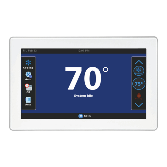
Link UX360
®
Smart Thermostat
Installation Guide
Model THUI2360A200U
With Link technology
ALL phases of this installation must comply with NATIONAL, STATE AND LOCAL CODES
IMPORTANT — This Document is customer property and is to remain with this unit.
These instructions do not cover all variations in systems or provide for every possible contingency to be met in connection
with the installation. Should further information be desired or should particular problems arise which are not covered
sufficiently for the purchaser's purposes, the matter should be referred to your installing dealer or local distributor.
18-HD98D1-1B-EN
Advertisement
Table of Contents
Troubleshooting

Related Manuals for Trane Link UX360


Summary of Contents for Trane Link UX360
- Page 1 Trane Link UX360 ® Smart Thermostat Installation Guide Model THUI2360A200U With Link technology ALL phases of this installation must comply with NATIONAL, STATE AND LOCAL CODES IMPORTANT — This Document is customer property and is to remain with this unit.
-
Page 2: Table Of Contents
Sensor Details ..........14 What’s in the Box? ......... 3 Assigning Sensors ........15 Accessories ........... 3 Unassigning Sensors ........15 4. Trane Link Systems ..........4 ® Adding Wireless Sensors ......15 5. Placement & Installation ........5 Removing Wireless Sensors ....... 16 Location ............ -
Page 3: Product Specifications
UX360 Smart Thermostat 2. Product Specifications Specification Description Model THUI2360A200U Product UX360 Smart Thermostat Size 7.125” x 4.725” x 1” (WxHxD) Configurations Heat Pump, Heat/Cool, Dual Fuel, Heat Only, Cooling Only Maximum Number of Stages 5 Stages Heat, 2 Stages Cooling Storage Temperature -40°F to +167°F, RH non-condensing Operating Temperature... -
Page 4: Trane Link Systems
No dealer visit or SD cards are required. Download the Trane Diagnostics mobile app from the Google Play™ Store or App Store ® 18-HD98D1-1B-EN All trademarks referenced are the trademarks of their respective owners. Google is a trademark of Google LLC. -
Page 5: Placement & Installation
UX360 Smart Thermostat 5. Placement & Installation 5.1 Location • Keep these 2 devices as far apart as possible. Never install them on top of each • Install the UX360 in a centrally located other. climate controlled living space with good air circulation. -
Page 6: Network Connections
Installation Guide 5.2 Network Connections Wiring To take advantage of the full range of features on the UX360, the SC360 System Controller should be connected to the Internet using a wireless connection. Refer to the UX360 User Guide for additional information on connecting to the Internet. -
Page 7: Field Wiring Connection Diagram Options
UX360 Smart Thermostat 6. Field Wiring Connection Diagram Options COMMUNICATING INDOOR AND OUTDOOR DISTRIBUTION SYSTEM BOARD CONTROLLER COMMUNICATING COMMUNICATING (SC360) (4x or 8x) INDOOR UNIT OUTDOOR UNIT THERMOSTAT (UX360) WIRE COLORS WHITE GREEN BLUE DISTRIBUTION SYSTEM BOARD CONTROLLER COMMUNICATING (4x or 8x) (SC360) INDOOR UNIT THERMOSTAT... -
Page 8: Can Low Voltage Troubleshooting
Installation Guide 7. CAN Low Voltage Troubleshooting Thermostat Distribution Board Air Handler Outdoor Unit (UX360) System Controller (SC360) • 24 VAC is required to power up the SC360 and UX360 • 24 VAC is required at the outdoor unit for Smart Charge automatic charging •... -
Page 9: Configuration
Enter a custom name for the system. Name keypad entry When the system is connected to Trane Home, a Dealer Code can be entered to populate the dealer’s contact information and logo. The code Manual is the dealer’s registered phone number listed on ComfortSite. A dealer... - Page 10 Installation Guide Sub Menu Menu Selection Options [Default] Description Heating Aggressive Select the outdoor temperature for 0°F -70°F [40°F] Recovery Setting (°F) Heating Aggressive Recovery. General System Operation Smart Control Fan Select to enable or disable Smart Enabled/[Disabled] Enable Status Continuous Fan.
-
Page 11: Energy
UX360 Smart Thermostat Sub Menu Menu Selection Options [Default] Description More Efficient/Efficient/ System Control Balanced/ Comfort/ [More Comfort] Minimum CFM Per Ton 200-500 [250] Compressor Minimum value based on Minimum Cooling CFM Per Ton setting. Maximum value Maximum CFM Per Ton 200-500 [500] based on Comp Cooling Maximum Airflow setting. -
Page 12: Accessories
Installation Guide 8.5 Accessories Available accessory menu selections will vary based on the accessory type. Sub Menu Menu Selection Options [Default] Description [None], Air Cleaner, Powered/Bypass, Accessory Type Select the accessory type. Steam, Ext Dehum, Ventilator [With Active Heat Call], Humidifier Action Without Active Heat Disabled for Air Cleaner accessory. - Page 13 UX360 Smart Thermostat Sub Menu Menu Selection Options [Default] Description [None], Condensate- Accessory Type Cooling, Smoke Select the accessory type. Detector Enabled by default for Condensate- Disable Compressor [Disabled]/Enabled Cooling and Smoke Detector Cooling accessories. ID External Disable Compressor Enabled by default for Smoke Detector [Disabled]/Enabled Switch Input Heating...
-
Page 14: Indoor Sensor Setup
Installation Guide 9. Indoor Sensor Setup View, edit and assign temperature and humidity sensors for the system. 9.1 Available Sensors 9.2 Sensor Details A list of all available sensors for the system will be Select a specific sensor to view more details displayed at the top of the Indoor Sensor Setup about the sensor and to assign it to the system. -
Page 15: Assigning Sensors
UX360 Smart Thermostat Assign or Unassign the sensor Enable/Disable temperature Enable/Disable humidity sensing Select a custom or predefined sensor name Select Custom to manually enter a sensor name 9.3 Assigning Sensors 9.4 Unassigning Sensors To assign a sensor to the system: To unassign a sensor: 1. -
Page 16: Adding Wireless Sensors
Installation Guide 9.5 Adding Wireless Sensors 9.6 Removing Wireless Sensors ZSENS930 wireless sensors must be added ZSENS930 wireless sensors must be removed to the system one at a time. from the system one at a time. The sensors must be online to be removed by the steps listed Follow these steps to add new wireless sensor: below. -
Page 17: System Operation
UX360 Smart Thermostat 10. System Operation 10.1 Power-Up Sequence Emergency Heating: system will run the • indoor heat source only (only available when When the UX360 is connected to the sub- the outdoor unit type is a heat pump) base, the thermostat initiates an 80 to 200 Auto: Mode of operation is automatically second power-up sequence. -
Page 18: Test Modes
Installation Guide 11. Test Modes Certain tests may or may not be present depending on other menu settings and equipment installed. Select the Start button to run each test. Menu Selection Options Description Energize indoor blower at the selected CFM. Test Blower 300-1580 CFM Range of values varies per Air Handler model. -
Page 19: Alerts
UX360 Smart Thermostat 13. Alerts The UX360 displays two sets of alerts: Major • Current Alerts: alerts which are currently • Reduced functionality - minimum operation is active possible • Alert History: alerts that have been cleared • Service call is not immediately required in the last 30 days •... - Page 20 Installation Guide Possible Causes Action Symptom 1. System mode is not set to Cool/ 1. Set mode to cool and lower the setpoint Auto or the setpoint is too high. below the room temperature. Cooling will not 2. Minimum off time delay is being 2.
- Page 21 Time set on UX360 UX360 is connected to Trane Home Correct the time zone from the Trane Home changes every 24 and the time zone set from the account. hours. Trane Home account is incorrect.
- Page 22 For more information, please visit trane.com or tranetechnologies.com. Trane has a policy of continuous data improvement and it reserves the right to change design and specifications without notice. We are committed to using environmentally conscious print practices.