Advertisement
Quick Links
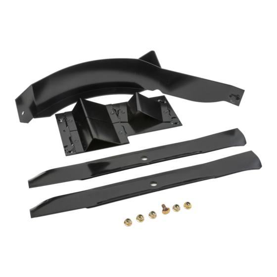
42in Mulching Kit
Zero-Turn-Radius Riding Mower
Model No. 131-7709
This product contains a chemical or chemicals known to the State of California to
Installation
Loose Parts
Use the chart below to verify that all parts have been shipped.
Procedure
1
2
3
4
WARNING
While maintenance or adjustments are being made,
someone could start the engine. Accidental starting
of the engine could seriously injure you or other
bystanders.
Remove the key from the ignition switch, engage
parking brake, and pull the wires off the spark plugs
before you do any maintenance. Push the wires
aside so they do not accidentally contact the spark
plugs.
Note: Determine the left and right sides of the machine
from the normal operating position.
Original Instructions (EN)
Proposition 65 Warning
cause cancer, birth defects, or reproductive harm.
Description
No parts required
No parts required
Baffle
Carriage bolt (5/16 x 3/4 inch)
Flange nut (5/16 inch)
Blade
Kicker plate
Mulching mower blade
WARNING
CALIFORNIA
Qty.
–
–
1
1
6
2
1
2
1
Preparing the Mower
No Parts Required
Procedure
1. Stop the engine and remove the ignition key.
2. Remove the mower as described in your Operator's
Manual.
3. Turn the mower upside down.
4. Remove and retain the existing discharge baffle and
mounting hardware as shown in
Form No. 3392-399 Rev A
Installation Instructions
Use
Prepare the mower.
Remove the blades.
Install the kit.
Install the blades and mower.
Figure
Printed in the USA
*3392-399* A
All Rights Reserved
1.
Advertisement

Related Manuals for Exmark 131-7709


Summary of Contents for Exmark 131-7709
- Page 1 Form No. 3392-399 Rev A 42in Mulching Kit Zero-Turn-Radius Riding Mower Model No. 131-7709 Installation Instructions WARNING CALIFORNIA Proposition 65 Warning This product contains a chemical or chemicals known to the State of California to cause cancer, birth defects, or reproductive harm.
- Page 2 Note: Retain the discharge baffle for reuse if the mulch kit is removed. Figure 2 Blade style A mounting configuration 1. Blade style A 4. Blade bolt G01801 1 2. Cross section of blade 5. Curved washer style A Figure 1 3.
- Page 3 Installing the Kit Parts needed for this procedure: Baffle Figure 5 Carriage bolt (5/16 x 3/4 inch) Flange nut (5/16 inch) 1. Kicker plate 3. Remove plug bolts and nuts Blade 2. Flange nut (5/16 inch) Kicker plate 3. Secure the kicker plate to the left side of the mower Procedure deck using 4 flange (5/16 inch) nuts as shown in Figure...
- Page 4 2. Reverse the steps in 3 Installing the Kit (page 2) remove the kicker plate and baffle assembly. 3. Install the discharge baffle. 4. Plug all open holes in the deck. Installing the Blades and 5. Install standard blades as described in the Operator’s Mower Manual.