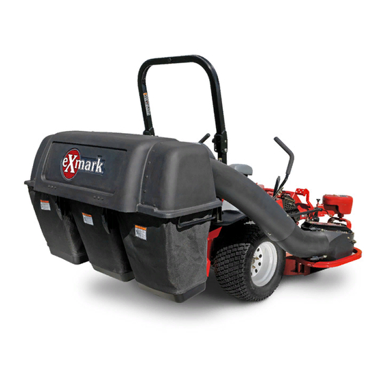
Exmark Ultravac Bagger 126-8680 Operator's Manual
Hide thumbs
Also See for Ultravac Bagger 126-8680:
- Operator's manual (24 pages) ,
- Setup instructions (6 pages)

Related Manuals for Exmark Ultravac Bagger 126-8680


Summary of Contents for Exmark Ultravac Bagger 126-8680
- Page 1 ULTRAVAC BAGGER ® 126-8680 For UltraVac Serial Nos. 406,294,345 & Higher (To fit Lazer Z Diesel Models 402,082,300 & Higher) Part No. 4504-786 Rev. A...
- Page 2 State of California to cause cancer, birth defects, or other reproductive harm. Exmark reserves the right to make changes or add improvements to its products at any time without incurring any obligation to make such changes to products manufactured previously.
-
Page 3: Introduction
All Exmark parts are thoroughly tested and inspected before leaving the factory, however, attention is required on your part if you are to obtain the fullest measure of satisfaction and performance. -
Page 4: Table Of Contents
Contents Introduction ............3 Safety ..............5 Safety Alert Symbol ......... 5 General Safety Information ......5 Safety and Instructional Decals ....... 6 Specifications ............8 Systems ............8 Dimensions............. 8 Torque Requirements ........8 Product Overview ..........8 Operation ............... 9 Before Operation .......... -
Page 5: Safety
General Safety Information This machine is capable of amputating hands and feet and of throwing objects. Exmark designed and tested this machine to offer reasonably safe service; however, failure to comply with safety instructions may result in injury or death. -
Page 6: Safety And Instructional Decals
Exmark equipment dealer or labels. distributor or from Exmark Mfg. Co. Inc. • Replace all worn, damaged, or missing safety • Safety signs may be affixed by peeling off the signs. - Page 7 Safety decal133-8061 133-8061 decal126-4584 126-4584 1. Impeller/Rotating Blades hazard-Keep hands away from moving parts. Keep all safety devices in place and working. Do Not reach into blower unless rotation indicator has stopped. Disengage PTO, stop engine, remove key, WAIT FOR MOVING PARTS TO STOP.
-
Page 8: Specifications
Product Overview Specifications Product Overview Systems Bagging System • Collection bins: – Commercial grade, cloth mesh bags with reinforced bottoms. – Capacity: 13.4 Bushels • Dump Mechanism: Manual lift off • Blower Tube: Fixed, abrasion resistant molded polyethylene. • Impeller: 5–bladed, 1/4 inch (6.4 mm) thick g241705 Figure 3 abrasion resistant steel, with vertical axis. -
Page 9: Operation
• Lightning can cause severe injury or death. If perform the job. Only use on machines approved lightning is seen or thunder is heard in the area, by Exmark. Do Not operate the machine; seek shelter. • Wear appropriate personal protective equipment •... - Page 10 Operation • Stop the blades, slow down, and use caution – Never allow children to operate the machine. when crossing surfaces other than grass and when – Do Not carry children, even with the blades transporting the mower to and from the area to shut off.
- Page 11 Operation Collection System Removal for Side Discharge Empty the hopper. CAUTION The hopper assembly is heavy when it is full, which may make it difficult to remove the hopper assembly from the unit. The entire hopper assembly may fall, which may cause injury.
- Page 12 Operation Install the discharge deflector using the chute pivot pin and hairpin (see Figure 7). g009319 Figure 7 1. Hairpin 3. Discharge deflector 2. Chute pivot pin WARNING An uncovered discharge opening will allow objects to be thrown in operator's or bystander's direction.
- Page 13 Operation Remove bracket assembly and all mounting hardware from the caster arm. Repeat for the RH side. Remove the caster weights by loosening the clamping knobs until the weight can be moved relative to the caster arm. Remove the hairpins and clevis pins that hold the weights to the caster arms.
- Page 14 Operation Remove the belt cover on the right side of the deck. Mount the blower on the deck by inserting the mounting pin into the tube welded to the rear corner of the deck (see Figure 11). Pivot the blower until the front pin engages the slot in the deck.
- Page 15 Operation Slide the lower end of the tube assembly over the blower outlet and align the notch with the tube latch. Latch the tube to the blower. Install the caster weights. On the LH side, insert the 3/8-16 x 6 1/2 inch screw into hole on the bottom side of the bracket and the rear of the removable 45 lb (20.4 kg) caster weight as shown in Figure 17.
-
Page 16: After Operation
Operation Secure the bottom of the bracket to the caster arm with a clevis pin and hairpin. Tighten the knob on weight assembly until it is clamped securely to the caster arm. Install three 20 lb (9.1 kg) caster weights over the weight assembly screw and stack them securely onto the 45 lb (20.4 kg) caster weight. -
Page 17: Maintenance
Inspect for wear or damage daily. Replace or Check bags frequently for tears and holes. repair worn parts as needed. Replace worn bags only with Exmark replacement bags. Note: When mowing in areas with sandy soil, use low lift blades on the cutting deck and higher... -
Page 18: Check Condition Of Belt
Maintenance Cleaning Refer to the following chart for fitting locations and lubrication schedule. Lubrication Chart Clean Muffler and Rear Frame Area Fitting Initial Number of Service Locations Pumps Places Interval Service Interval: Before each use or daily 1. Idler 1–2 25 Hours Bushings Stop engine, wait for all moving parts to stop, and... -
Page 19: Troubleshooting
Troubleshooting Troubleshooting Important: It is essential that all operator safety mechanisms be connected and in proper operating condition prior to mower use. When a problem occurs, Do Not overlook the simple causes. For example: starting problems could be caused by an empty fuel tank. The following table lists some of the common causes of trouble. -
Page 20: Information
While the exposure from Exmark products may be negligible or well within the “no significant risk” range, out of an abundance of caution, Exmark has elected to provide the Prop 65 warnings. Moreover, if Exmark does not provide these warnings, it could be sued by the State of California or by... - Page 21 Notes:...
- Page 22 Notes:...
- Page 23 Service Record Date: Description of Work Done: Service Done By:...
- Page 24 Place Model No. and Serial No. Date Purchased Label Here (Included in the Literature Pack) or Fill in Below Model No. Serial No. ©2019 Exmark Mfg. Co., Inc. Part No. 4504-786 Rev. A 2101 Ashland Ave (402) 223-6375 Beatrice, NE 68310 Fax (402) 223-5489...