Table of Contents
Troubleshooting

Related Manuals for Agilent Technologies 85024A


Summary of Contents for Agilent Technologies 85024A
- Page 1 User’s and Service Guide Agilent Technologies 85024A High Frequency Probe Agilent Part Number 85024-90031 Printed in USA July 2013 Supersedes May 2012 Copyright © 1989–2013 Agilent Technologies, Inc. All rights reserved.
- Page 2 This product is warranted against defects in material and workmanship for a period of one year from date of shipment. During the warranty period, Agilent Technologies will, at its option, either repair or replace products which prove to be defective.
- Page 3 How to Use This Guide This guide uses the following conventions: This represents a key physically located on the instrument. Front Panel Key This represents a “softkey”, a key whose label is determined by the SOFTKEY instrument firmware. CAUTION Caution denotes a hazard. It calls attention to a procedure that, if not correctly performed or adhered to, would result in damage to or destruction of the instrument.
-
Page 5: Table Of Contents
Contents 1. General Information Read This Before Using Your Probe............1-2 Input Voltage Tolerances . - Page 6 Contents Performing a Response Calibration ...........5-4 Median Gain and Frequency Response Flatness .
-
Page 7: General Information
General Information... -
Page 8: Read This Before Using Your Probe
General Information Read This Before Using Your Probe Read This Before Using Your Probe Your probe has been designed to provide years of uninterrupted service. Excellent performance at high frequencies requires the use of very small and delicate devices. Such components can be damaged by careless use. -
Page 9: Anti-Static Precautions
General Information Anti-Static Precautions Anti-Static Precautions Electrostatic discharge (ESD) is a serious problem; take consistent steps to eliminate it. This is important whenever using your probe. • Never touch the tip of the probe. The probe microcircuit is susceptible to damage by static discharge. •... -
Page 10: Product Description
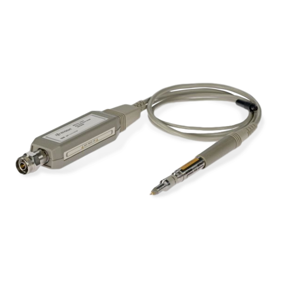
General Information Product Description Product Description Your high frequency probe is an active probe that provides low input capacitance, high input impedance, and wide bandwidth. The probe may be used with a variety of network analyzers, spectrum analyzers, frequency counters, and oscilloscopes. The probe allows the testing of high frequency RF circuits. -
Page 11: Specifications
General Information Specifications Specifications Table 1-1 Product Performance Performance Parameter Value a, b Code Input Capacitance <0.7pF Input Resistance 1 M Bandwidth 300 kHz to 3 GHz (usable to 100 kHz) Median Gain 0 dB 1.25 dB (mid-point between max and min gains, 300 kHz to 1 GHz) Frequency Response Flatness: 1.25 dB 300 kHz to 1.0 GHz... -
Page 12: General Characteristics
General Information General Characteristics General Characteristics Physical Characteristics Characteristics Value 130 cm (51 inches) Probe Length Net Weight 0.3 kg (0.66 pounds) Shipping Weight 2.3 kg (5.1 pounds) Overall length: includes wand, leads, and regulator assembly. Environmental Characteristics Environmental Requirements Operating Storage ... -
Page 13: Accessories
Accessories... -
Page 14: Probe Features And Accessories
Accessories Probe Features and Accessories Probe Features and Accessories Figure 2-1 Probe Features Chapter 2... - Page 15 11524A Adapter, type-N female to Precision 7 mm 1250-1477 Adapter, type -N female to BNC male 85024A-001 External DC Power Supply Adapter Cable a. Used with the 85046A S-Parameter test set. b. Used with the 8590A spectrum analyzer. c. Requires E3620A, E3630A, E3631A External Power Supply from Agilent Technologies.
-
Page 16: Probe Adapter
Accessories Probe Adapter Probe Adapter Description The probe adapter fits over the tip of the probe and converts the probe input to a 50 type-N male connector. The adapter is only used when performance testing the probe. Operating Characteristics 50 ... -
Page 17: 10:1 Divider
Accessories 10:1 Divider 10:1 Divider The 10:1 divider fits over the tip of the probe and provides the following changes to the probe’s operating parameters: • Increases (by a factor of 10) the input voltage at which 1 dB compression occurs. •... -
Page 18: Replaceable Parts
Accessories 10:1 Divider Replaceable Parts If the tip is discolored, bent or broken, it must be replaced. Follow the procedure outlined in “Replacing the Probe Tip,” below. Figure 2-2 Exploded View of 10:1 Divider Item Description Part Number Short probe tip 85024-60015 Long probe tip 85024-60016... -
Page 19: Installation
Installation... -
Page 20: Initial Inspection
Chapter 5 , “Performance Tests.” Notify the nearest Agilent Technologies office if the product does not pass performance tests, the shipping contents are incomplete, or if there is mechanical damage or defect. Notify the carrier if the shipping container is damaged or if the cushioning material shows signs of stress. -
Page 21: Preparation For Use
• Make sure the device under test (DUT) is at the same ground potential as the probe. Power Requirements If using the probe with an instrument that does not supply probe power, you can purchase an 85024A-001 adapter cable assembly and one of the following Agilent external power supplies: E3620A E3630A E3631A ... -
Page 22: Mating Connectors
Installation Mating Connectors Mating Connectors CAUTION Periodically inspect and, if necessary, clean the type-N output connector. Refer to Chapter 7, “Connector Inspection and Cleaning,” on page 15. The probe adapter should be inspected at the same time, and cleaned if necessary. Chapter 3... -
Page 23: Returning The Product For Service
Table 7-1 on page 7-17. When shipping the probe to Agilent Technologies please include a blue service tag (found at the end of this manual) and a valid return mailing address. Products cannot be returned to a post office box. Provide the name and phone number of a contact person within your organization, the complete model and serial number of the product, and a complete description of the problem. - Page 24 Installation Returning the Product for Service Chapter 3...
-
Page 25: Operation
Operation... -
Page 26: Operating Precautions
Operation Operating Precautions Operating Precautions CAUTION Electrostatic discharge (ESD), excessive input signals or mechanical shock can dramatically degrade the performance of the probe. Be sure to observe the following precautions. • Never touch the tip of the probe! • Always hold the probe by the retracted metal sleeve. •... -
Page 27: Operating Instructions
Operation Operating Instructions Operating Instructions CAUTION Discharging the Probe Between Measurements Measuring a node having a DC voltage potential charges blocking capacitors inside of the probe. Ground the probe tip after measuring such nodes to discharge the probe capacitors. Failure to do this can result in damage to sensitive circuits in the DUT, especially if it is an active device. -
Page 28: Operator's Check
Operation Operator’s Check Operator’s Check The operator’s check is designed to be a simple functional test for the probe. If the probe fails the operator’s check, or if you need to verify that the probe meets its warranted specifications, you will need to do the performance tests as described in Chapter 5 , “Performance Tests.”... -
Page 29: Operator's Check Using A Spectrum Analyzer
Operation Operator’s Check Operator’s Check Using a Spectrum Analyzer Required Equipment Item Part Number Spectrum Analyzer Any Compatible Adapters As Necessary Probe Adapters 11880-60001 Procedure 1. Connect the spectrum analyzer’s calibration output directly to its RF input. Turn on the spectrum analyzer. - Page 30 Operation Operator’s Check Chapter 4...
-
Page 31: Performance Tests
Performance Tests... - Page 32 All tests must pass for the performance test to be verified. NOTE The performance tests in this chapter cover the specifications for a standard 85024A probe. If the serial number label indicates an option, contact Agilent Technologies for applicable specifications. Refer to...
-
Page 33: Recommended Test Equipment
Performance Tests Recommended Test Equipment Recommended Test Equipment Table 5-1 lists the equipment that is recommended for use in performance testing of the probe. Other equipment may be substituted if its specifications meet or exceed the specifications listed in the “Critical Specifications”... -
Page 34: Network Analyzer Operation
Performance Tests Recommended Test Equipment Network Analyzer Operation This section provides some general information for performing basic network analyzer operations. For more specific operating information, refer to your analyzers user’s guide. Presetting the Network Analyzer All analyzers have a hardkey for this function. PRESET Selecting a Transmission (or S21 Measurement) 871x family... -
Page 35: Median Gain And Frequency Response Flatness
Performance Tests Median Gain and Frequency Response Flatness Median Gain and Frequency Response Flatness Specifications (at 25 °C 5 °C) 0 dB 1.25 dB Median Gain over 300 kHz to 1 GHz Frequency Response Flatness (Relative to Median Gain) 1.25 dB 300 kHz to 1 GHz 2.5 dB 1 GHz to 3 GHz... -
Page 36: Gain Compression
Performance Tests Gain Compression Gain Compression Specifications (at 25 °C 5 °C) .0 dB at 0.3 V Peak In a 50 system V Peak 0.458 dBm Description This test identifies the frequency of greatest compression at a signal level of 0.3 V peak ( 0.458 dBm). -
Page 37: Calculating Equivalent Power
Performance Tests Gain Compression 16. Connect the probe, the probe adapter, and a barrel between the attenuator and the power sensor. The signal from the analyzer should now go through the attenuator and then the probe before reaching the power sensor. Record the power reading on the “Test Record”... -
Page 38: Average Noise Level
Performance Tests Average Noise Level Average Noise Level Specifications (at 25 °C 5 °C): <17 mV RTI (or 23 dBm at probe output) Description This test procedure uses a power meter to measure the power level of the probe output when the probe tip is connected through 50 ohms to ground. -
Page 39: Test Record
Performance Tests Average Noise Level Test Record 85024A High Frequency Probe Test Record Serial Number: Date: Tested By: Temperature: Median Gain and Frequency Response Flatness Limits Results Pass/ Fail Maximum gain over 300 kHz to 1 GHz Minimum gain over 300 kHz to 1 GHz... - Page 40 Performance Tests Average Noise Level 5-10 Chapter 5...
-
Page 41: Replaceable Parts
Replaceable Parts... -
Page 42: Introduction And Ordering Information
To order a part listed in the replaceable parts list, indicate the Agilent part number and the quantity desired. Address the order to the nearest Agilent Technologies office. To order a part that is not listed in the replaceable parts list, include the probe model and serial number, the description and function of the part and the quantity desired. -
Page 43: Parts Lists
Replaceable Parts Parts Lists Parts Lists Table 6-1 Miscellaneous Replacement Parts Part Number Description 08405-40003 Anti-Static Protection Cap 1401-0214 Protective End Cap for type-N Connector 85024-90031 Operating and Service manual 85024-80001 Side Label 85024-80003 Product Case 85024-80004 Bottom Foam of the Product Case 5180-8448 Top Foam of the Product Case 41800-61672... - Page 44 Replaceable Parts Parts Lists Table 6-2 Replaceable Parts Part Number Description Item 85024-60013 Connector Replacement Kit 85024-20024 RF Bead 85024-20016 Transition-Nut 85024-20017 Transition-REG 0515-0912 Screw-Machined M3 x 0.5 8 mm-LG Pan Head 85024-20028 Frame Casting 85024-20025 Nut, Strain Relief 85024-60014 Cable/Probe Wand Kit (pre-assembled) 0515-0659 Screw-Machined M2 8 mm-LG Pan Head...
- Page 45 Replaceable Parts Parts Lists Figure 6-1 Replaceable Parts Identification * CAUTION Failure to remove the nose assembly prior to replacing the tip will result in damage to the conductive elastometer on the tip assembly. ** NOTE Item 11 is a nut which slides over items 12 through 17 and screws onto the end of the heat sink.
- Page 46 Replaceable Parts Parts Lists Chapter 6...
-
Page 47: Service
Service... -
Page 48: Introduction
Service Introduction Introduction This chapter contains troubleshooting and repair information. Heed caution signs to avoid damaging the probe. You may wish to read the “Theory of Operation” on page 7-3, with its associated diagrams as an aid to troubleshooting. Before You Troubleshoot Troubleshooting the probe begins with performing the “Operator’s Check”... -
Page 49: Theory Of Operation
Service Theory of Operation Theory of Operation The probe uses a Gallium Arsenide FET integrated circuit amplifier which provides unity gain. This amplifier microcircuit requires +6 V and 4 Vdc to operate. These voltages are provided by the regulator assembly. The regulator assembly converts the +15 volt and 12.6 volt supplies from the host instrument with two voltage regulators. -
Page 50: Troubleshooting Procedures
Service Troubleshooting Procedures Troubleshooting Procedures CAUTION The probe contains an input GaAs amplifier microcircuit that is highly sensitive to electrostatic discharge (ESD). When repairing this probe, you must use an anti-static wrist strap, and work at a station equipped with an anti-static surface! Before you take a measurement with a digital multimeter, discharge the leads by touching them to ground. - Page 51 Service Troubleshooting Procedures Figure 7-2 A1 Regulator Schematic Diagram and Overall Block Diagram Figure 7-3 High Frequency Probe Chapter 7...
- Page 52 Service Troubleshooting Procedures 3. Connect the probe’s power cord to the power source. Turn the power source on. 7-4. Check the +6 V and 4 V power supply voltages on the exposed portion of the 4. Refer to Figure probe end. •...
- Page 53 Service Troubleshooting Procedures Figure 7-5 A1 Regulator Assembly 85024-63071 1. Components on the regulator board are nonpurchasable items. Chapter 7...
-
Page 54: Replacement Procedure
Service Replacement Procedure Replacement Procedure Replacing the Probe Tip Tools Required: 3/32 inch probe-tip nut driver (supplied with the probe) 10 mm open-end wrench CAUTION Use static precautions when performing the following procedures. The amplifier microcircuit is very static sensitive and exposed during this procedure. Refer to Figure 7-6. -
Page 55: Replacing The Amplifier Microcircuit
Service Replacement Procedure Replacing the Amplifier Microcircuit Tools Required: 10 mm open-end wrench Small flatblade screwdriver Refer to Figure 7-6. 1. Remove the nose assembly. 2. Remove the amplifier microcircuit. Refer to Figure 7-7. 3. Remove and discard the spring clip and elastic conductive strip. 4. -
Page 56: Removing The Plastic Regulator Housing Covers
Service Replacement Procedure Removing the Plastic Regulator Housing Covers Tools Required: 1/8 inch-wide flatblade screwdriver WARNING In the steps below, hold the regulator housing and screwdriver so that you won’t injure yourself if the screwdriver slips. Refer to Figure 7-8. 1. -
Page 57: Replacing The Type-N Output Connector
Service Replacement Procedure Replacing the Type-N Output Connector Tools Required: 9/16 inch open-end wrench Refer to Figure 7-9. 1. Remove the connector body with the open-end wrench. 2. Remove the male center conductor assembly from the gold plated inner connector. Use your fingers to pull out the assembly. -
Page 58: Cable/Probe Wand Replacement
Service Replacement Procedure Cable/Probe Wand Replacement Tools Required: 10 mm open-end wrench 9/16 inch open-end wrench 1/8 inch-wide flatblade screwdriver Phillips No. 0 or posidrive screwdriver Long-nose pliers Special Tool: Spanner/wrench (part number 85024-20041) This special tool is pictured in Figure 7-10 on page 7-13. - Page 59 Service Replacement Procedure 12. Screw the inner connector onto the new RF cable and insert the inner conductor into the keyed hole. 13. Attach the transition nut with the spanner wrench. 14. Screw on the connector body and tighten with the 9/16 inch wrench. 15.
- Page 60 Service Replacement Procedure Figure 7-11 Regulator Parts and Wiring 7-14 Chapter 7...
-
Page 61: Connector Inspection And Cleaning
Service Connector Inspection and Cleaning Connector Inspection and Cleaning The following is a brief introduction to the fundamentals of proper connector care. Proper connector care is essential to making accurate valid measurements. Inspecting the Connectors Visual and mechanical inspection of the output connector and adapter should be done periodically. CAUTION If a bad connector is accidentally attached to a good connector, the good connector can be damaged. - Page 62 Service Connector Inspection and Cleaning WARNING Always use protective eyewear when using compressed air or nitrogen. You can use any source of clean, dry, low-pressure compressed air or nitrogen that has an effective oil-vapor filter and liquid condensation trap placed just before the outlet hose. Ground the hose nozzle to prevent electrostatic discharge, and set the air pressure to less than 414 kPa (60 psi) to control the velocity of the air stream.
- Page 63 Service Connector Inspection and Cleaning Table 7-1 Agilent Technologies Sales and Service Offices UNITED STATES Instrument Support Center Agilent Technologies (800) 403-0801 EUROPEAN FIELD OPERATIONS Headquarters France Germany Agilent Technologies S.A. Agilent Technologies France Agilent Technologies GmbH Agilent 150, Route du Nant-d’Avril ...
- Page 64 Service Connector Inspection and Cleaning 7-18 Chapter 7...
- Page 65 Index Numerics network analyzer spectrum analyzer 1 dB compression failure 10 to 1 divider electrical mechanical protective sleeve parts frequency response relative to 500 identification accessories miscellaneous adapter, probe replaceable anti-static precautions performance tests average noise level average noise level gain at 500 MHz gain at 500 MHz/frequency response gain compression...
- Page 66 Index gain at 500 MHz/frequency response input voltage for 1 dB compression flatness gain compression median gain median gain operator’s check using a network probe adapter analyzer product performance operator’s check using a spectrum protective sleeve analyzer extension of test record retraction of tests, performance theory of operation...