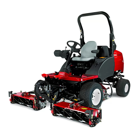
Toro LT2240 Operator's Manual
Compact triple 4-wheel drive turf mower
Hide thumbs
Also See for LT2240:
- Installation instructions manual (28 pages) ,
- Installation instructions manual (40 pages)

Related Manuals for Toro LT2240


Summary of Contents for Toro LT2240
- Page 1 Form No. 3441-251 Rev C LT2240 Compact Triple 4-Wheel Drive Turf Mower Model No. 31654—Serial No. 400000000 and Up *3441-251* Register at www.Toro.com. Original Instructions (EN)
-
Page 2: Table Of Contents
Whenever you need service, genuine Toro parts, or Operator’s Seat Controls....... 14 additional information, contact an Authorized Service Transport Latches ........16 Dealer or Toro Customer Service and have the model Specifications ..........17 and serial numbers of your product ready. Figure 1 Attachments/Accessories ......... - Page 3 Maintenance ............32 Checking the Hydraulic Fluid Level ....53 Maintenance Safety.......... 32 Changing the Hydraulic Return Filter ....54 Recommended Maintenance Schedule(s) ... 32 Changing the Transmission Fluid Filter ..... 54 Daily Maintenance Checklist......34 Replacing the Transmission Dampener .... 55 Pre-Maintenance Procedures ......
-
Page 4: Safety
Safety This machine has been designed in accordance with EN ISO 5395. General Safety This product is capable of amputating hands and feet and of throwing objects. • Read and understand the contents of this Operator’s Manual before starting the engine. •... -
Page 5: Safety And Instructional Decals
Safety and Instructional Decals Safety decals and instructions are easily visible to the operator and are located near any area of potential danger. Replace any decal that is damaged or missing. decal93-9084 93-9084 decal111-3562 111-3562 1. Lift point/Tie-down point 1. Press the pedal to adjust the steering wheel angle. decal93-6686 93-6686 1. - Page 6 decal117-3276 117-3276 1. Engine coolant under 3. Warning—do not touch the pressure hot surface. 2. Explosion hazard—read 4. Warning—read the the Operator's Manual. Operator's Manual. decal134-4281 134-4281 1. Warning—read the 4. If the roll bar is raised, Operator's Manual. wear the seat belt. decal120-0625 120-0625 2.
- Page 7 decal134-5122 134-5122 1. Warning—shut off the engine and remove the key before releasing or operating the safety latches. decal134-5139 134-5139 decal134-4539 1. Warning—read the 3. Tipping hazard—lower 134-4539 Operator’s Manual; wear attachments when hearing protection; remove operating on hills/slopes; 1. Falling, crushing hazard—ensure that the operator-platform the key before performing do not turn sharply while latch is engaged before operating.
- Page 8 decal134-1807 134-1807 1. Slope indicator 7. Raise 2. Right cutting unit controls 8. Fast 9. Engine speed 3. Center cutting unit controls 4. Left cutting unit controls 10. Slow 11. Horn 5. Lower/float 6. Transport...
-
Page 9: Setup
Setup Media and Additional Parts Description Qty. Operator's Manual Read the manuals before operating the machine. Engine owner’s manual Store all documentation in a safe place for future use. Note: Determine the left and right sides of the machine from the normal operating position. Product Overview Controls Control Console Controls... - Page 10 g348129 Figure 5 1. Horn button Throttle Control • To increase the engine speed, move the g348147 Figure 7 throttle-control lever (Figure 6) forward. 1. Auto reverse limited-lift switch • To decrease engine speed, move the throttle-control lever rearward. Note: Engine speed influences the speed of the Ignition Key other functions, i.e.
- Page 11 Note: The LED light in the switch illuminates when Lift-Control Switches the parking brake is engaged and the ignition key is Use the lift-control switches to raise and lower the turned to the R position. cutting units (Figure g348146 Figure 9 1.
-
Page 12: Control Console Indicators
Control Console Indicators g348164 Figure 14 1. Low engine-oil pressure warning light Engine Coolant Overheating Warning Light The engine coolant warning light illuminates, the horn is actuated, and the cutting units stop (Figure 15). g348058 Figure 12 1. Battery warning indicator 5. - Page 13 Traction Pedals Transmission Neutral Indicator Light The transmission neutral indicator light illuminates Forward travel: Press the forward traction pedal when the traction pedals are in the N position EUTRAL to drive the machine forward and increase ground and the ignition key is turned to the R position speed.
-
Page 14: Operator's Seat Controls
Operator Weight Adjustment Rotate the handle clockwise to increase suspension stiffness and counterclockwise to decrease the stiffness. The dial indicates when the seat suspension is adjusted for the operator’s weight (kg); refer to Figure g014549 Figure 20 Operator’s Seat Controls Forward/Backward Adjustment Move the lever upward to adjust the forward/backward position of the seat. - Page 15 Fuel Gauge The fuel gauge shows the amount of fuel in the tank (Figure 25). g348122 Figure 23 1. Handle g348110 Figure 25 Backrest Adjustment Pull the handle outward to adjust the seat backrest angle. Release the handle to lock the seat backrest in position (Figure 24).
-
Page 16: Transport Latches
Transport Latches Front Cutting Unit Arm Latches Raise the cutting units to the T position and RANSPORT secure the arm-latch pins to the latches with the bails (Figure 26). g327358 Figure 26 1. Bails (front cutting-unit arm latches) Rear Cutting Unit Arm Latch Raise the cutting units to the T position, RANSPORT... -
Page 17: Specifications
32 L (8.5 US gallons) Attachments/Accessories A selection of Toro approved attachments and accessories is available for use with the machine to enhance and expand its capabilities. Contact your Authorized Service Dealer or authorized Toro distributor or go to www.toro.com/en-gb for a list of all approved attachments and accessories. -
Page 18: Before Operation
Performing Daily Operation Maintenance Before Operation Before starting the machine each day, perform the Each Use/Daily procedures listed in Maintenance Before Operation Safety (page 32). Filling the Fuel Tank General Safety • Never allow children or untrained people to Service Interval: Before each use or daily operate or service the machine. -
Page 19: Understanding The Operator-Presence Controls
You may expect a plugged fuel filter plugging for a operating the machine. period after converting to biodiesel blends. • Contact your authorized Toro distributor for more information on biodiesel. Adding Fuel Park the machine on a level surface, lower the cutting units, shut off the engine, engage the parking brake, and remove the key. -
Page 20: During Operation
causes distractions; otherwise, injury or property CAUTION damage may occur. If safety interlock switches are disconnected • Before you start the engine, ensure that all drives or damaged, the machine could operate are in neutral, the parking brake is engaged, and unexpectedly, causing personal injury. -
Page 21: Machines With A Foldable Roll Bar
• Keep the ROPS in safe operating condition by – Be aware that operating the machine on wet thoroughly inspecting it periodically for damage grass, across slopes, or downhill may cause and keeping all the mounting fasteners tight. the machine to lose traction. •... -
Page 22: Raising The Roll Bar
g348269 Figure 30 1. Roll-bar pin (lower position) Secure roll-bar pins to the pivot brackets with the hairpins. g348268 Figure 32 Raising the Roll Bar 1. Roll-bar pin 3. Hairpin 2. Pivot bracket upper hole 4. Upper roll bar (lower roll-bar frame) Remove the hairpins that secure the roll-bar pins to the pivot brackets of the lower roll-bar frame. -
Page 23: Using The Cutting Units
Starting the Engine Shutting off the Engine Sit on the seat, keep your foot off the traction Keep your foot off the traction pedals so that pedals so that they return to the N they return to the N position, engage the EUTRAL EUTRAL position, engage the parking brake, and set the... -
Page 24: Controlling The Position Of The Individual Cutting Units
g348146 Figure 36 1. Left (front) cutting-unit lift 3. Right (front) cutting-unit lift g327581 Figure 35 switch switch 2. Rear cutting unit lift switch Adjusting the Center Cutting Unit Raising the Cutting Unit Height-of-Cut Correction Pull and hold the lift-control switch. With all cutting units set at the same HOC as shown Release the lift-control switches when the cutting by the indicator rings, the center cutting unit may... -
Page 25: Cutting Unit Drive
Important: The cutting units continue to run while driving in reverse with the auto-limited lift in reverse engaged. Operating the Machine with the Auto-Limited Lift in Reverse Engaged Press the auto-limited lift in reverse switch to the position (Figure 38). g348287 Figure 39 1. -
Page 26: Clearing The Cutting Units
Clearing the Cutting Units downward to the tires. This action is known as weight transfer. Note: Adjust the amount of weight transfer to suit WARNING operating conditions. Never attempt to rotate the cutting units by Park the machine on a level surface, engage hand. -
Page 27: After Operation
After Operation continuing operation. Serious damage could occur if you operate the machine with a malfunction. General Safety Mowing Grass • Park the machine on a level surface. To maintain the high quality of cut, keep the rotational speed of the cutting units as high as possible. This •... -
Page 28: Identifying The Tie-Down Points
Identifying the Tie-Down Chock the front wheels of the machine. Raise the platform forward; refer to Raising the Points Platform (page 35). Remove the 2 bolts (12 x 40 mm) and 2 washers (12 mm) stored in the platform support rails (Figure 42). - Page 29 Important: You must manually steer the machine while it is towed. When the engine is shut off, there is no hydraulic steering assist—steering the machine feels heavy. g292377 Figure 44 1. Hex plug Assemble a bolt (12 x 40 mm) and washer (12 mm) into the hole at the center of the motor end plate (Figure...
- Page 30 Restoring the Transmission Pump Restoring the Brakes Chock the front wheels. Remove the bolt (12 x 40 mm) and washer (12 mm) from the hole at the center of the motor end Raise the platform forward; refer to Raising the plate (Figure 48).
- Page 31 Stow the 2 bolts (12 x 40 mm) and 2 washers (12 mm) stored in the platform support rails (Figure 49). g292366 Figure 50 1. Bolt (12 x 40 mm) and 2. Platform support rail washers (12 mm) Lower the platform; refer to Lowering the Platform (page 35).
-
Page 32: Maintenance
Note: Determine the left and right sides of the machine from the normal operating position. Note: To obtain an electrical schematic or a hydraulic schematic for your machine, visit www.toro.com/en-gb. Maintenance Safety • If possible, do not perform maintenance while the engine is running. - Page 33 Maintenance Service Maintenance Procedure Interval • Check the transmission-control cable. Every 250 hours • Inspect the cooling-system hoses. • Check the engine speed (idle and full throttle). • Replace the fuel filter. Every 400 hours • Check the fuel lines and connections for deterioration, damage, or loose connections. •...
-
Page 34: Daily Maintenance Checklist
Daily Maintenance Checklist Duplicate this page for routine use. For the week of: Maintenance Check Item Mon. Tues. Wed. Thurs. Fri. Sat. Sun. Check the safety interlock operation. Check the brake operation. Check the engine-oil and fuel levels. Check the air-filter restriction indicator. Check the radiator and screen for debris. -
Page 35: Pre-Maintenance Procedures
Pre-Maintenance Lowering the Platform Procedures WARNING Operating the machine with the platform Preparing the Machine for unlatched may cause you to lose control of Maintenance the machine, resulting in serious injury to you and bystanders. Park the machine on a level surface. Never operate the machine without first Engage the parking brake. -
Page 36: Removing The Storage Compartment
Installing the Storage Fully lower the platform and move the platform-latch handle toward the rear of the Compartment machine until the latch hooks fully engage the locking bar (Figure 55). Align the holes on the bottom of the storage compartment with the holes in the chassis brackets. -
Page 37: Raising The Mower Off The Ground
If raising the front of the machine, chock the rear wheels to prevent the machine from rolling away. Note: The parking brake operates only on the front wheels. Support the machine with jack stands. g014447 Figure 58 1. Front left lift point 3. -
Page 38: Lubrication
Lubrication Greasing the Bearings, Bushings, and Pivots Service Interval: Before each use or daily—Lubricate the grease-daily fittings. Every 50 hours—Lubricate the grease every 50-hour fittings. Important: Lubricate the bearings, bushings, and pivot points immediately after every washing, regardless of the service interval listed. Grease specification: No. -
Page 39: Engine Maintenance
Engine Maintenance Touch the metal terminal of this wire onto a suitable earth point, ensuring that the metal surfaces make good contact. Engine Safety Note: The horn sounds and the engine coolant temperature warning light illuminates to confirm • Shut off the engine before checking the oil or operation. -
Page 40: Replacing The Primary Air Filter
Replacing the Primary Air Inspect the new filter for shipping damage, checking the sealing end of the filter and the Filter body. Important: Do not use a damaged element. Service Interval: Every 500 hours Insert the new filter by applying pressure to the Check the air-cleaner body for damage that could outer rim of the element to seat it in the canister. -
Page 41: Servicing The Engine Oil
Preferred oil: SAE 15W-40 (above 0°F) • Alternate oil: SAE 10W-30 or 5W-30 (all temperatures) Toro Premium Engine Oil is available from your g348420 Figure 64 authorized Toro distributor in either 15W-40 or 10W-30 viscosity grades. See the parts catalog for part 1. -
Page 42: Extended Engine Maintenance
Extended Engine Maintenance Service Interval: After the first 50 hours—Check the engine speed (idle and full throttle). Every 400 hours—Check the engine speed (idle and full throttle). g348419 Figure 66 1. Oil pan (engine) 3. Drain plug (engine oil) 2. Gasket When all the oil is drained, install the drain plug. -
Page 43: Fuel System Maintenance
Replacing the Fuel Filter Fuel System Maintenance Service Interval: Every 400 hours Important: Replace the fuel filter canister periodically to prevent wear of the fuel injection DANGER pump plunger or the injection nozzle, due to dirt Under certain conditions, diesel fuel and fuel in the fuel. -
Page 44: Checking The Fuel Lines And Connections
Electrical System Maintenance Electrical System Safety • Disconnect the battery before repairing the machine. Disconnect the negative terminal first and the positive last. Connect the positive terminal first and the negative last. • Charge the battery in an open, well-ventilated area, away from sparks and flames. -
Page 45: Checking The Electrical System
Figure 71 any loose connections. 1. Fuse holder (maxi fuse) 3. Fuse-block cover Apply Grafo 112X skin-over grease (Toro Part No. 505-47) or petroleum jelly to the terminals. 2. Maxi fuse-holder cover 4. Fuse block (ACT/ATO blade) Clean the battery compartment. -
Page 46: Drive System Maintenance
Drive System Maintenance Checking the Tire Pressure Check the air pressure in the front and rear tires. Refer to the following chart for the correct pressure. Important: Maintain correct tire pressure in all tires to ensure correct contact with the turf. Tires Tire Recommended Tire Pressures... -
Page 47: Inspecting The Transmission Control Cable And Operating Mechanism
Inspecting the Turn the steering wheel to align the rear wheels in the straight ahead. Transmission Control Prepare the machine for maintenance; refer to Cable and Operating Preparing the Machine for Maintenance (page 35). Mechanism At axle height, measure the distance between the front of the rear wheels and between the Service Interval: Every 250 hours rear of the rear wheels. -
Page 48: Cooling System Maintenance
Cooling System Maintenance Cooling System Safety • Swallowing engine coolant can cause poisoning; keep out of reach from children and pets. g348714 Figure 75 • Discharge of hot, pressurized coolant or touching a hot radiator and surrounding parts can cause 1. - Page 49 g348599 Figure 78 1. Oil-cooler latches Rotate the oil cooler latches inward, and pivot the oil cooler (Figure 78 Figure 79). g348598 Figure 77 Unlatch and open the hood (Figure 77). Clean the inside of the hood screens with compressed air (Figure 77).
-
Page 50: Checking The Coolant Level
Checking the Coolant Level Service Interval: Before each use or daily The cooling system is filled with a 50/50 solution of water and permanent ethylene glycol antifreeze. Check the level of coolant in the expansion tank at the beginning of each day before starting the engine. CAUTION If the engine has been running, the pressurized, hot coolant can escape and... -
Page 51: Belt Maintenance
Belt Maintenance Tensioning the Alternator Belt Service Interval: After the first 50 hours Every 100 hours Prepare the machine for maintenance; refer to Preparing the Machine for Maintenance (page 35). Unlatch and open the hood. g348613 Figure 83 1. Tension bracket bolt 4. -
Page 52: Controls System Maintenance
Controls System Hydraulic System Maintenance Maintenance Checking the Hydraulic System Safety Forward/Reverse Travel • Seek immediate medical attention if fluid is injected into skin. Injected fluid must be surgically removed Pedal Action within a few hours by a doctor. • Ensure that all hydraulic-fluid hoses and lines are With the engine shut off, operate the forward and in good condition and all hydraulic connections... -
Page 53: Hydraulic Fluid Specifications
Toro. 1. Hydraulic-tank cap This fluid is compatible with the elastomers used 2. Fluid tank in Toro hydraulic systems and is suitable for a 3. Sight-level gauge wide-range of temperature conditions. This fluid is compatible with conventional mineral oils, but... -
Page 54: Changing The Hydraulic Return Filter
Important: Do not overfill the tank with Assemble the filter to the filter head, and tighten hydraulic fluid. the filter by hand until the gasket contacts the mounting surface, then rotate it an additional 1/2 Install the cap onto the tank. turn (Figure 85). -
Page 55: Replacing The Transmission Dampener
Service Interval: Every 2 years—Replace the hydraulic fluid. transmission dampener. Every 500 hours—If you are not using the Refer to your authorized Toro distributor for a new recommended hydraulic fluid or have ever dampener kit. filled the reservoir with an alternative fluid, Raise the platform;... -
Page 56: Cutting Unit Maintenance
Cleaning the Strainers Cutting Unit Maintenance Remove the storage compartment; refer to Removing the Storage Compartment (page 36). Blade Safety Remove the oil tank suction flange to gain access to the suction strainer (Figure 89). A worn or damaged blade or bedknife can break, and a piece could be thrown toward you or bystanders, resulting in serious personal injury or death. -
Page 57: Grinding The Cutting Units
The only exception to this rule is when a new reel is installed, in which case only grind the bedknife. • Have your authorized Toro dealer grind your reel blades and bedknives on a quality, well-maintained reel/bedknife grinding machine. g014445... -
Page 58: Chassis Maintenance
Chassis Maintenance Cleaning Inspecting the Seat Belt Washing the Machine Service Interval: Before each use or daily Wash the machine as needed using water alone or with a mild detergent. You may use a rag when Inspect the seat belt for wear, cuts, and other washing the machine. -
Page 59: Storage
Coat the cable terminals and battery posts with as on a water heater or other appliance. Grafo 112X skin-over grease (Toro Part No. 505-47) or petroleum jelly to prevent corrosion. Preparing the Traction Unit Slowly charge the battery every 60 days for 24 hours to prevent lead sulfation of the battery. -
Page 60: Troubleshooting
Troubleshooting Problem Possible Cause Corrective Action There are areas of uncut grass at the 1. You are turning too tightly. 1. Increase the turning radius. overlap between cutting units. 2. The machine slides sideways when 2. Mow up/down the slope. driving the machine across the face of a slope. - Page 61 Problem Possible Cause Corrective Action There is scalping of the turf. 1. The undulations are too severe for the 1. Use floating cutting units. height of cut setting. 2. The height of cut is too low. 2. Raise the height of cut. There is excessive bedknife wear.
- Page 62 Problem Possible Cause Corrective Action There is no machine movement in forward 1. The parking brake is engaged. 1. Disengage the parking brake. or reverse. 2. The fluid level is low. 2. Fill the reservoir to the correct level. 3. The reservoir has the wrong kind of 3.
- Page 63 4. The pressure relief valve is jammed 4. Have the relief valve pressure open or wrongly set. checked. Consult your authorized Toro distributor. 5. A cutting unit is jammed. 5. Clear any jams as necessary.
- Page 64 Notes:...
- Page 65 Notes:...
- Page 66 The Toro Company (“Toro”) respects your privacy. When you purchase our products, we may collect certain personal information about you, either directly from you or through your local Toro company or dealer. Toro uses this information to fulfil contractual obligations - such as to register your warranty, process your warranty claim or to contact you in the event of a product recall - and for legitimate business purposes - such as to gauge customer satisfaction, improve our products or provide you with product information which may be of interest.
- Page 67 Countries Other than the United States or Canada Customers who have purchased Toro products exported from the United States or Canada should contact their Toro Distributor (Dealer) to obtain guarantee policies for your country, province, or state. If for any reason you are dissatisfied with your Distributor's service or have difficulty obtaining guarantee information, contact your Authorized Toro Service Center.