Toro LT2240 Installation Instructions Manual
Hide thumbs
Also See for LT2240:
- Installation instructions manual (40 pages) ,
- Operator's manual (68 pages)
Advertisement
Quick Links
Vinyl or Fabric Air Ride Seat Kit
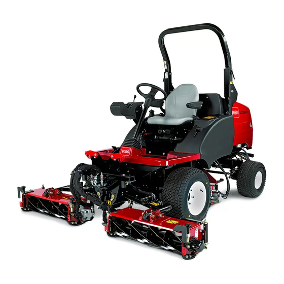
LT2240 Compact Triple 4-Wheel Drive Turf Mower, LT3340 Triple
Reel Mower, or LT-F3000 Triple Flail Mower
Model No. 02875-Serial No. 400000000 and Up
Model No. 02876-Serial No. 400000000 and Up
Installation
Loose Parts
Use the chart below to verify that all parts have been shipped.
Procedure
1
2
3
4
5
6
7
8
9
© 2021-The Toro® Company
8111 Lyndale Avenue South
Bloomington, MN 55420
Description
No parts required
No parts required
Locknut (8 mm)
Hex-head bolt (8 x 25 mm)
Register at www.Toro.com.
Form No. 3440-878 Rev A
Installation Instructions
Qty.
-
Prepare the machine.
Remove the existing seat (model
-
31654).
Remove the existing seat (models
-
31657 and 31659).
1
Prepare the new seat (model 31654).
Prepare the new seat (models 31657
1
and 31659).
4
Install the seat (model 31654).
4
4
Install the seat (models 31657 and
31659).
4
1
Connect the electrical components.
1
-
Complete the seat kit installation.
Original Instructions (EN)
Printed in the USA
All Rights Reserved
Use
*3440-878*
Advertisement

Related Manuals for Toro LT2240


Summary of Contents for Toro LT2240
-
Page 1: Table Of Contents
Form No. 3440-878 Rev A Vinyl or Fabric Air Ride Seat Kit LT2240 Compact Triple 4-Wheel Drive Turf Mower, LT3340 Triple Reel Mower, or LT-F3000 Triple Flail Mower Model No. 02875—Serial No. 400000000 and Up Model No. 02876—Serial No. 400000000 and Up... - Page 2 Preparing to Install the Seat No Parts Required Preparing the Machine g290372 Figure 2 Park the machine on a level surface. Lower the cutting units. Engage the parking brake. Shut off the engine and remove the key. Wait for all moving parts to stop. Allow the engine to cool completely.
- Page 3 Removing the Storage Disconnecting the Battery Compartment Loosen the forward nut of the negative battery-cable terminal (Figure At the left side of the operator’s platform, open the door of the storage compartment (Figure g344733 Figure 4 1. Nut (negative 2. Negative battery post battery-cable terminal) Lift the negative battery cable from the battery post...
- Page 4 Remove the boot from the seat base as follows (Figure At the sides of the seat-base boot, locate its mounting tabs that protrude through the slot Removing the Existing Seat in the channel of the seat base. Model 31654 No Parts Required Procedure Seat weight: 38 kg (84 lb) Note:...
- Page 5 While supporting the seat, remove the 4 washers (8 mm) and 4 locknuts (8 mm) that secure the seat to the seat platform (Figure Note: Do not remove the 4 bolts (8 x 25 mm) from the holes in the seat and seat platform. g036780 Figure 7 1.
-
Page 6: No Parts Required
Removing the Existing Seat Models 31657 and 31659 No Parts Required Procedure Seat weight: 38 kg (84 lb) Note: Have another person help you remove the seat or use a suitable crane. Disconnect the main wire-harness connector from the control-arm harness (Figure Rotate the collar and pull the connector to remove. - Page 7 Remove the boot from the seat base as follows (Figure At the sides of the seat-base boot, locate its mounting tabs that protrude through the slot in the channel of the seat base. g037076 g037047 Figure 9 1. Tabs (seat-base boot) 2.
- Page 8 While supporting the seat, remove the 4 locknuts (8 mm) that secure the seat to the seat platform (Figure 10). Do not remove the 4 bolts (8 x 25 mm) from the holes in the seat and seat platform. g343902 Figure 10 Lower the operator’s platform as follows: Lower the platform carefully...
- Page 9 g290371 Figure 11 As the platform nears the fully lowered position, move the platform-latch handle (Figure 12) toward the front of the machine. Note: This ensures that the latch hooks clear the locking bar. g290369 Figure 12 1. Platform-latch handle 2.
-
Page 10: Seat And Suspension Assembly
Assemble the seat belt onto the new seat and install the previously removed armrest using the previously removed nut (Figure 15). Set the armrest to be the same height as the Preparing the New Seat other side. Torque the seat belt bolts to 70 to 75 N∙m (52 to 55 ft-lb) and install the covers (Figure 15). -
Page 11: Seat And Suspension Assembly
Preparing the New Seat Models 31657 and 31659 Parts needed for this procedure: Seat and suspension assembly Removing the Control Arm and Seat Belt from the Seat Place the seat and control arm onto a bench. Remove the seat cushion to gain access to the flange nut securing the control arm to the seat (Figure 16). - Page 12 Remove the plastic cover on the left side and loosen the bolt to remove the seat-belt retainer from the seat (Figure 17). g344860 Figure 17...
- Page 13 Ensure that the control arm is supported sufficiently before removing. Remove the existing hex-head bolt (7/16 x 2 inches), 2 washers, seat belt, and spacer (Figure 18). Retain the hex-head bolt (7/16 x 2 inches), 2 washers, seat belt, and spacer for later installation. g344019 Figure 18 1.
- Page 14 Remove the hex-head bolt (8 x 10 mm), coupling hex nut (8 mm), and washer (8 mm) from the top of the seat arm (Figure 19). Retain the hex-head bolt (8 x 10 mm), coupling hex nut (8 mm), and washer (8 mm) for later installation. g345727 Figure 19 Installing the Control Arm and Seat Belt to the New Air Ride Seat...
- Page 15 Locate the previously removed control arm and brackets. Secure the previously removed fasteners as shown in Figure Apply Loctite ® 243 to the hex-head bolt (7/16 x 2 inches) and torque the hex-head bolt (7/16 x 2 inches) to 70 to 75 N∙m (52 to 55 ft-lb). g344019 Figure 21 1.
- Page 16 Installing the Seat Model 31654 Parts needed for this procedure: Locknut (8 mm) Hex-head bolt (8 x 25 mm) g345847 Figure 23 Procedure 1. Hex-head bolt (8 x 25 mm) 2. Flange (seat-bottom plate) At the bottom plate of the new seat, locate the seat-mounting holes for your machine (Figure 22).
- Page 17 Installing the Seat Models 31657 and 31659 Parts needed for this procedure: Hex-head bolt (8 x 25 mm) Locknut (8 mm) Procedure At the bottom plate of the new seat, locate the seat-mounting holes for your machine (Figure 25). g344774 Figure 25...
-
Page 18: Hex-Head Bolt (8 X 25 Mm)
Secure the seat assembly to the platform using the 4 hex-head bolts (8 x 25 mm) and 4 locknuts (8 mm) as shown in Figure g345728 Figure 26 1. Hex-head bolt (8 x 25 mm) 2. Locknut (8 mm) Fully raise the platform. Torque the 4 locknuts (8 mm) to 27 N∙m (20 ft-lb). -
Page 19: Standard Fuse (10A)-Model 31654
Insert the standard fuse (10 A) into the 5th fuse position from the left (Figure 28) of the fuse block as follows: Note: Ensure that the fuse is fully seated. Connecting the Electrical Components Parts needed for this procedure: Standard fuse (10A)—Model 31654 Mini fuse (10 A)—Models 31657 and 31659 Model 31654 g037201... - Page 20 Models 31657 and 31659 Connect the main wire-harness connector to the control arm that you disconnected in Removing the Existing Seat (page Locate the connector labeled AIR-RIDE on the seat behind the rubber boot. Locate the air-ride seat connector on the main wire harness breakout and install the connector.
-
Page 21: No Parts Required
Installing the Storage Compartment Align the holes on the bottom of the storage compartment with the holes in the chassis Completing the Seat Kit brackets. Installation Assemble the storage compartment to the machine with the 3 knobs and 3 washers (Figure 31). - Page 22 Lowering the Operator’s Platform Fully lower the platform and move the platform-latch handle toward the rear of the machine until the latch hooks fully engage the WARNING locking bar (Figure 34). Operating the machine with the platform unlatched may cause you to lose control of the machine, resulting in serious injury to you and bystanders.
- Page 23 Product Overview Weight and Height Adjustment Lever Use this lever to adjust to the proper weight of the operator (Figure 35). Pull up the lever to increase Controls the air pressure and push down to decrease the air pressure. The proper adjustment is correct when the weight and height gauge is in the green region.
- Page 24 Maintenance Greasing the Seat Suspension Mechanism Service Interval: Yearly Pull back the rubber boot from the channel of the seat base. Apply good quality grease to all pivot points of the suspension mechanism. Install the boot onto the channel of the seat base.
- Page 25 Notes:...
- Page 26 Notes:...
- Page 27 The Toro Company (“Toro”) respects your privacy. When you purchase our products, we may collect certain personal information about you, either directly from you or through your local Toro company or dealer. Toro uses this information to fulfil contractual obligations - such as to register your warranty, process your warranty claim or to contact you in the event of a product recall - and for legitimate business purposes - such as to gauge customer satisfaction, improve our products or provide you with product information which may be of interest.
- Page 28 Countries Other than the United States or Canada Customers who have purchased Toro products exported from the United States or Canada should contact their Toro Distributor (Dealer) to obtain guarantee policies for your country, province, or state. If for any reason you are dissatisfied with your Distributor's service or have difficulty obtaining guarantee information, contact your Authorized Toro Service Center.