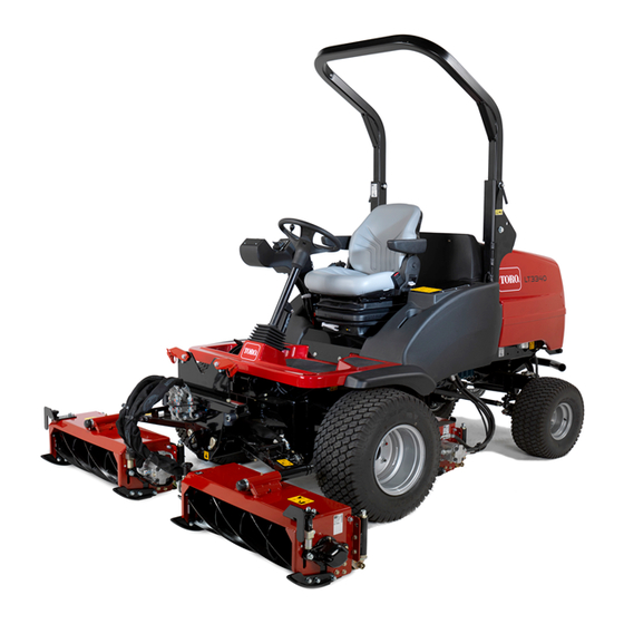
Toro LT3340 Operator's Manual
4 wheel drive triple reel mower
Hide thumbs
Also See for LT3340:
- Operator's manual (60 pages) ,
- Installation instructions manual (28 pages) ,
- Addendum (4 pages)

Related Manuals for Toro LT3340


Summary of Contents for Toro LT3340
- Page 1 Form No. 3431-797 Rev B LT3340 4 Wheel Drive Triple Reel Mower Model No. 31657—Serial No. 400000000 and Up *3431-797* Register at www.Toro.com. Original Instructions (EN)
-
Page 2: Table Of Contents
Whenever you need service, genuine Toro parts, or Setup ................ 9 additional information, contact an Authorized Service Product Overview ............. 9 Dealer or Toro Customer Service and have the model Controls ............. 9 and serial numbers of your product ready. Figure 1 Operator’s Seat Controls........11... - Page 3 Identifying the Tie-Down Points ......30 Hydraulic Fluid Specifications......52 Hauling the Machine ......... 30 Checking the Hydraulic Fluid Level ....52 Towing the Machine .......... 30 Changing the Hydraulic Return Filter ....53 Maintenance ............34 Changing the Hydraulic Fluid ......53 Maintenance Safety..........
-
Page 4: Safety
Safety • Do not operate the machine without all guards and other safety protective devices in place and functioning properly on the machine. This machine has been designed in accordance with • Keep bystanders and children out of the operating EN ISO 5395. - Page 5 decal111-3562 111-3562 1. Press the pedal to adjust the steering wheel angle. decal121-3884 121–3884 1. Engine—stop 3. Engine—start 2. Engine—preheat decal120-0625 120-0625 1. Pinch point, hand—keep hands away. decal121-3887 121–3887 decal127-0392 127-0392 1. Read the Operator’s Manual. 1. Warning—stay away from hot surfaces. decal111-3567 111-3567 1.
- Page 6 decal134-1828 134-1828 1. 8 hour service interval 10. Check the operation of the seat switch. 2. Read the Operator’s Manual. 11. Check the air filter element. 3. 50 hour service interval 12. Check the cutting unit settings. 4. Check the tire pressure. 13.
- Page 7 decal119-4988 119-4988 1. Lock 2. Unlock decal134-4539 134-4539 1. Falling, crushing hazard—ensure that the operator-platform latch is engaged before operating. decal134-5122 134-5122 decal134-4281 1. Warning—shut off the engine and remove the key before 134-4281 releasing or operating safety latches. 1. Warning—read the 4.
- Page 8 decal134-4280 134-4280 Note: This machine complies with the industry standard stability test in the static lateral and longitudinal tests with the maximum recommended slope indicated on the decal. Review the instructions for operating the machine on slopes in the Operator’s Manual as well as the conditions in which you would operate the machine to determine whether you can operate the machine in the conditions on that day and at that site.
-
Page 9: Setup
Setup Media and Additional Parts Description Qty. Operator's Manual Read the manuals before operating the machine. Engine owner’s manual CE certificate The certificate indicates CE compliance. Store all documentation in a safe place for future use. Note: Determine the left and right sides of the machine from the normal operating position. Product Overview Controls Control Panel Components... - Page 10 Key Switch Parking-Brake Switch Use the key switch to control the engine and power to WARNING certain electrical components. The parking brake affects the front wheels only, and may not keep the machine from rolling down a slope. The machine could move unintentionally.
-
Page 11: Operator's Seat Controls
Traction Pedals Forward travel: Press the forward traction pedal to drive the machine forward and increase ground speed. Release the pedal to reduce ground speed (Figure Reverse travel: Press the reverse traction pedal to drive the machine backward and increase ground speed. - Page 12 Operator Weight Adjustment Rotate the handle clockwise to increase suspension stiffness and counterclockwise to decrease the stiffness. The dial indicates when the seat suspension is adjusted for the operator’s weight (kg); refer to Figure g327324 Figure 11 1. Handle Backrest Adjustment Pull the handle outward to adjust the seat backrest angle.
-
Page 13: Transport Latches
Fuel Gauge The fuel gauge shows the amount of fuel in the tank (Figure 13). g327359 Figure 15 1. Latch arm (rear cutting-unit 2. Front of the machine arm latch) g295232 Figure 13 Transport Latches Front Cutting Unit Arm Latches Raise the cutting units to the T position and RANSPORT... - Page 14 Using the InfoCenter LCD Display InfoCenter Icon Descriptions SERVICE DUE Indicates when scheduled service The InfoCenter LCD display shows information about should be performed your machine, such as the operating status, various diagnostics, and other information about the machine Hours remaining until service (Figure 16).
- Page 15 Menu Item Description drive the machine back to the shop Hours Lists the total number of hours and contact your authorized Toro that the machine, engine, and distributor (software version U and PTO have been on, as well later). as the number of hours the The power take-off is disabled.
- Page 16 To lock these settings, use the Protected Menu. Settings Note: At the time of delivery, the initial password code is programmed by your authorized Toro distributor. Menu Item Description Units Controls the units used on the Accessing Protected Menus...
- Page 17 Viewing and Changing the Protected Menu Settings In the Protected Menu, scroll down to Protect Settings and perform 1 of the following: • To view and change the settings without entering a PIN code, and use the right button to change the Protect Settings to O •...
-
Page 18: Specifications
Specifications and design are subject to change without notice. Attachments/Accessories A selection of Toro approved attachments and accessories is available for use with the machine to enhance and expand its capabilities. Contact your Authorized Service Dealer or authorized Toro distributor or go to www.toro.com/en-gb... -
Page 19: Before Operation
Performing Daily Operation Maintenance Before Operation Before starting the machine each day, perform the Each Use/Daily procedures listed in Maintenance (page 34). Before Operation Safety Filling the Fuel Tank General Safety • Never allow children or untrained people to Fuel Tank Capacity operate or service the machine. -
Page 20: Checking The Forward/Reverse Traction Pedal Action
• Contact your authorized Toro distributor for more information on biodiesel. Checking the Operator Presence Adding Fuel Seat Switch Park the machine on a level surface, lower the Sit on the operator’s seat and start the engine. -
Page 21: During Operation
Checking the Transmission Set the cutting-unit-drive switch to the forward-cut position. Neutral Interlock Switch Rise from the operator’s seat and check that the Important: Take extreme care to ensure that the cutting units stop after an initial 0.5 to 1 second area around the machine is clear before checking delay. - Page 22 • • Keep your hands and feet away from the cutting Lower a folding roll bar temporarily only when units. necessary. Do not wear the seat belt when the roll bar is folded down. • Look behind and down before backing up to be •...
-
Page 23: Understanding The Operator Presence Controls
Understanding the Adjusting the Roll Bar Operator Presence WARNING Controls To avoid injury or death from rollover, keep the roll bar in the raised locked position and CAUTION use the seat belt. If safety interlock switches are disconnected Ensure that the seat is secured with the seat or damaged the machine could operate latch. - Page 24 Lowering the Roll Bar Raising the Roll Bar Park the machine on a level surface, lower the Remove the hairpins that secure the roll-bar pins cutting units, engage the parking brake, shut off to the pivot brackets of the lower roll-bar frame. the engine, and remove the key.
-
Page 25: Starting The Engine
Starting the Engine Press the engine speed switch until the engine speed is at low idle. Important: If you are starting the engine for the Let the engine run for at least 5 minutes. first time, the engine has stopped from lack of fuel, or you performed fuel system maintenance, Turn the key to shutoff (stop) position (Figure... -
Page 26: Controlling The Position Of The Individual Cutting Units
Adjusting the Center Cutting Unit Raising the Cutting Unit Height-of-Cut Correction Pull and hold the lift-control switch. Release the lift-control switches when the cutting With all cutting units set at the same HOC as shown units are at the needed height. by the indicator rings, you may notice that the center cutting unit produces a higher cut finish compared to Note:... -
Page 27: Adjusting The Cutting Unit Auto-Limited Lift
Adjusting the Cutting Unit Engaging the Cutting Unit Drive for Reverse Rotation Auto-Limited Lift Press the bottom of the cutting unit drive switch to the Note: You enable the cutting-unit Auto Limited Lift reverse rotation position (Figure 28). feature in the settings menu of the InfoCenter. •... -
Page 28: Clearing The Cutting Units
Clearing the Cutting Units WARNING Never attempt to rotate the cutting units by hand. Residual pressure in the hydraulic system could cause the cutting unit(s) to rotate suddenly when you release the blockage, which may cause serious injury. • Always wear protective gloves and use a suitable strong wooden instrument. -
Page 29: After Operation
Understanding the InfoCenter Driving the Machine in Transport Engine Warnings Mode Important: If while operating the machine an icon displays on Take care when driving the machine the InfoCenter warning you of a condition, stop the over obstacles such as roadside curbs. machine immediately and correct the problem. -
Page 30: Identifying The Tie-Down Points
Identifying the Tie-Down Remove the 2 bolts 12 x 40 mm and 2 washers 12 mm stored in the platform support rails Points (Figure 31). g292366 Figure 31 1. Bolt 12 x 40 mm and 2. Platform support rail washers 12 mm Connect a rigid tow bar between the front tow ring of the machine and the tow vehicle (Figure... - Page 31 g292377 Figure 33 1. Hex plug Assemble a bolt 12 x 40 mm and washer 12 mm into the hole at the center of the motor end plate (Figure 34). g328252 Figure 35 1. Socket head plugs (transmission pump-relief valves) Lower and latch the platform;...
- Page 32 Restoring the Transmission Pump Restoring the Brakes Chock the front wheels. Remove the bolt 12 x 40 mm and washer 12 mm from the hole at the center of the motor end Raise the platform forward; refer to Raising the plate (Figure 37).
- Page 33 g292366 Figure 39 1. Bolt 12 x 40 mm and 2. Platform support rail washers 12 mm Lower the platform; refer to Lowering the Platform (page 37). Disconnect the tow vehicle. Check the brake operation of the machine. WARNING Operating the machine without the braking system working properly may cause you to lose control of the machine, resulting in serious injury to you and...
-
Page 34: Maintenance
• To ensure safe, optimal performance of the – Shut off the engine and remove the key. machine, use only genuine Toro replacement – Wait for all movement to stop. parts. Replacement parts made by other manufacturers could be dangerous, and such use •... - Page 35 Maintenance Service Maintenance Procedure Interval • Replace the primary air filter. • Change the engine oil and filter. • Replace the fuel filter. • Replace the engine fuel filter. • Check the fuel lines and connections for deterioration, damage, or loose connections Every 500 hours •...
-
Page 36: Daily Maintenance Checklist
Daily Maintenance Checklist Duplicate this page for routine use. For the week of: Maintenance Check Item Mon. Tues. Wed. Thurs. Fri. Sat. Sun. Check the engine oil level. Check the air filter-blockage indicator. Drain water the fuel/water separator. Check for fluid leaks. Check the cooling system. -
Page 37: Pre-Maintenance Procedures
Pre-Maintenance Lowering the Platform Procedures WARNING Operating the machine with the platform Raising the Platform unlatched may cause you to lose control of the machine, resulting in serious injury to you Move the platform-latch handle (Figure and bystanders. toward the front of the machine until the latch hooks clear the locking bar. -
Page 38: Removing The Storage Compartment
Installing the Storage Fully lower the platform and move the platform-latch handle toward the rear of the Compartment machine until the latch hooks fully engage the locking bar (Figure 44). Align the holes on the bottom of the storage compartment with the holes in the chassis brackets. -
Page 39: Locating The Lift Points
Locating the Lift Points Note: Use jack stands to support the machine when you lift it. WARNING Mechanical or hydraulic jacks may fail to support the machine and cause serious injury. Use jack stands when supporting the machine. • Front—under the front arm mount •... -
Page 40: Lubrication
Lubrication Greasing the Bearings, Bushings, and Pivots Service Interval: Before each use or daily—Lubricate the grease-daily fittings. Every 50 hours—Lubricate the grease every 50-hour fittings. Important: Lubricate the bearings, bushings, and pivot points immediately after every washing, regardless of the service interval listed. Grease specification: No. -
Page 41: Engine Maintenance
Engine Maintenance damaged. Check the whole intake system for leaks, damage, or loose hose clamps. Note: Service the primary air filter when the Engine Safety filter-blockage indicator (Figure 49) is red. Changing • Shut off the engine before checking the oil or the air filter frequently increases the chance of dirt adding oil to the crankcase. -
Page 42: Replacing The Safety Filter
Align the dirt ejection port air-filter cover between temperatures) 5 o’clock to 7 o’clock when viewed from the end, Toro Premium Engine Oil is available from your assemble the cover to the canister, and secure authorized Toro distributor in either 15W-40 or 10W-30 the cover. -
Page 43: Servicing The Diesel-Oxidation Catalyst (Doc) And The Soot Filter
Remove the oil filter. soot filter of the DPF. Apply a light coat of clean oil to the oil filter Refer to your authorized Toro distributor for gasket. diesel-oxidation catalyst and the soot filter replacement parts or service. -
Page 44: Extended Engine Maintenance
Extended Engine Fuel System Maintenance Maintenance Service Interval: Every 1,000 hours Refer to the DANGER Engine Service Manual. Under certain conditions, fuel and fuel vapors Every 1,500 hours—Inspect the crankcase breather system. Contact an Authorized Service are highly flammable and explosive. A fire or Dealer. -
Page 45: Priming The Fuel System
Drain the fuel filter canister; refer to Servicing the Water Separator (page 44). Clean the area around the fuel filter and filter head (Figure 56). g292479 Figure 55 1. Vent screw 2. Drain valve (water separator filter) g292477 Figure 56 Tighten the drain valve at the bottom of the filter 1. -
Page 46: Servicing The Engine Fuel Filter
Servicing the Engine Fuel Electrical System Filter Maintenance Service Interval: Every 500 hours—Replace the Important: Before welding on the machine, engine fuel filter. disconnect both cables from the battery, both wire harness plugs from the electronic control Note: Refer to the engine owner's manual included modules, and the terminal connector from the with the machine for additional information. -
Page 47: Checking The Electrical System
Apply Grafo 112X skin-over grease (Toro Part No. 505-47) or petroleum jelly to the terminals. Clean the battery compartment. Remove the cell covers and if needed add distilled water to a height 15 mm below the top of the battery. -
Page 48: Drive System Maintenance
Inspecting the Drive System Transmission Control Maintenance Cable and Operating Checking the Tire Air Mechanism Pressure Service Interval: Every 250 hours Check the condition and security of the cable and Service Interval: Before each use or daily operating mechanism at the speed-control pedals and Important: Maintain correct tire pressure in all transmission pump ends. -
Page 49: Cooling System Maintenance
Cooling System Note: The end of the tie rod with the external groove is a left-hand thread. Maintenance Cooling System Safety • Swallowing engine coolant can cause poisoning; keep out of reach from children and pets. • Discharge of hot, pressurized coolant or touching a hot radiator and surrounding parts can cause severe burns. -
Page 50: Checking The Coolant Level
g292487 Figure 63 Clean the screens. g328487 Figure 65 Unlatch and open the hood (Figure 64). 1. Radiator Close and latch the hood. Assemble the screen onto the pivot pins, close the screen and secure it with the latch and ball pin. -
Page 51: Belt Maintenance
Belt Maintenance Servicing the Alternator Belt Service Interval: After the first 50 hours Every 250 hours Apply 10 kgf (22 lb) of force against the alternator belt (Figure 67), midway between the pulleys. Note: g330219 The belt should deflect 10 mm (3/8 inch). Figure 66 1. -
Page 52: Hydraulic System Maintenance
Service Interval: Before each use or daily This fluid is compatible with the elastomers used in Toro hydraulic systems and is suitable for a Check the hydraulic lines and hoses for leaks, kinked wide-range of temperature conditions. This fluid is... -
Page 53: Changing The Hydraulic Return Filter
Every 500 hours—If you are not using the change the hydraulic fluid. recommended hydraulic fluid or have ever filled the reservoir with an alternative fluid, If the fluid becomes contaminated, contact your replace the hydraulic filters. authorized Toro distributor to flush the system. - Page 54 Contaminated fluid looks milky or black when compared to clean fluid. Draining the Hydraulic Fluid Park the machine on a level surface, lower the cutting units, shut off the engine, engage the parking brake, and remove the key. Remove the storage compartment; refer to Removing the Storage Compartment (page 38).
-
Page 55: Cutting Units
Cutting Units 80-grade carborundum paste Part number 0.45 kg (1 lb) 63-07-088 Blade Safety 11.25 kg (25 lb) 63-07-086 A worn or damaged blade or bedknife can break, and a piece could be thrown toward you or bystanders, resulting in serious personal injury or death. •... -
Page 56: Grinding The Cutting Units
Service Interval: Before each use or daily bedknife. • Have your authorized Toro dealer grind your reel Check the machine for loose and missing fasteners. blades and bedknives on a quality, well-maintained Note: Tighten any loose fasteners;... -
Page 57: Cleaning
Cleaning Storage Storage Safety Washing the Machine • Shut off the engine, remove the key, and wait Wash the machine as needed using water alone for all movement to stop before you leave the or with a mild detergent. You may use a rag when operator’s position. -
Page 58: Preparing The Engine
Clean the battery, terminals, and posts with a wire brush and baking-soda solution. Coat the cable terminals and battery posts with Grafo 112X skin-over grease (Toro Part No. 505-47) or petroleum jelly to prevent corrosion. Slowly charge the battery every 60 days for 24... -
Page 59: Troubleshooting
Troubleshooting Problem Possible Cause Corrective Action There are areas of uncut grass at the 1. You are turning too tightly. 1. Increase the turning radius. overlap between cutting units. 2. The machine slides sideways when 2. Mow up/down the slope. driving the machine across the face of a slope. - Page 60 Problem Possible Cause Corrective Action There is scalping of the turf. 1. The undulations are too severe for the 1. Use floating cutting units. height of cut setting. 2. The height of cut is too low. 2. Raise the height of cut. There is excessive bedknife wear.
- Page 61 Problem Possible Cause Corrective Action There is no machine movement in forward 1. The parking brake is engaged. 1. Disengage the parking brake. or reverse. 2. The fluid level is low. 2. Fill the reservoir to the correct level. 3. The reservoir has the wrong kind of 3.
- Page 62 Problem Possible Cause Corrective Action A cutting unit fails to lift out of work. 1. There is a lift cylinder seal failure. 1. Replace the seals. 2. The pressure relief valve is jammed 2. Have the relief valve pressure checked. open or wrongly set.
- Page 63 The Toro Company (“Toro”) respects your privacy. When you purchase our products, we may collect certain personal information about you, either directly from you or through your local Toro company or dealer. Toro uses this information to fulfil contractual obligations - such as to register your warranty, process your warranty claim or to contact you in the event of a product recall - and for legitimate business purposes - such as to gauge customer satisfaction, improve our products or provide you with product information which may be of interest.
- Page 64 Countries Other than the United States or Canada Customers who have purchased Toro products exported from the United States or Canada should contact their Toro Distributor (Dealer) to obtain guarantee policies for your country, province, or state. If for any reason you are dissatisfied with your Distributor's service or have difficulty obtaining guarantee information, contact your Authorized Toro Service Center.