Table of Contents

Related Manuals for Neilsen CT2206


Summary of Contents for Neilsen CT2206
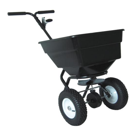
- Page 1 100LB WALK BEHIND SPREADER CT2206 INSTRUCTION MANUAL SAVE THESE INSTRUCTIONS AND PRECAUTIONS. READ ALL PRECAUTONS AND INSTRUCTIONS BEFORE USE. Cannon Tools Limited Address: 20 Station Road, Rowley Regis, West Midlands, B65 0JU.U.K.
-
Page 2: Ec Declaration Of Conformity
In case of alteration of the machine, not agreed upon by us, this declaration will lose its validity. Product description: 100 LB WALK-BEHIND SPREADER Model: CT2206 Applicable EC Directives: EC Machinery Directive 2006/42/EC Harmonized standards... -
Page 3: Specifications
1. SPECIFICATIONS Capacity: 100LB Spread Width: 10'-12'/3048mm-3658mm Plastic Tyre: 12" Coverage: 20000 sq/ft Heavy duty nylon gear. Rate setting control on handle for precise adjustments. Accessories: screen & rain cover 2. GENERAL SAFETY INSTRUCTIONS Warning: When using tool, basic safety precautions should always be followed to reduce the risk of personal injury and damage to equipment. - Page 4 CONDITIONS. We recommend the machine is not used during winds. This may affect the spreading pattern. DRESS PROPERLY. Do not wear loose clothing, gloves, scarfs, neckties or jewellery (rings, wrist watches), which can be caught in moving parts. DO NOT OVERREACH. Keep proper footing and balance at all times when using the machine.
-
Page 5: Controls And Features Identification
3. CONTROLS AND FEATURES IDENTIFICATION Read this owner’s manual before operating the equipment. Familiarize yourself with the location and function of the controls and features. Save this manual for future reference. 1) Handle – Pushes and moves the spreader easily. 2) Flow Control –... -
Page 6: Tools Required
4. ASSEMBLY AND OPERATING INSTRUCTIONS 1. HELPFUL HINTS: READ THE INSTRUCTIONS BEFORE ASSEMBLY This push spreader is designed to spreader a wide range of materials (Fertilizer and Grass Seed). Materials such as Powders, Manure, Top Soil, Gravel, and Mulch have the wrong physical characteristics and should not be used with this spreader. - Page 7 3. ASSEMBLY STEP 1: Install impeller onto the Gear Box 1.Insert Screw M4x20 through impeller then through gear box axle.
- Page 8 STEP 2: Install Wheel Assembly Frame on the Gear Box 1. Make sure the hole on axle of gear box is on the right side of the assembly as shown below. Attach one end of frame brace to hopper frame assembly using bolts M6 x 35 and lock nuts M6.
- Page 9 STEP 3: Insert Inner Axle Bushing into Outer Axle Bushing 1. Make sure everything has been tightened. Install the right tire assembly to right axle using bolt M5 x 45 and lock nut M5, and then install nylon washer and end cap onto right axle using a wooden or rubber hammer.
- Page 10 STEP 4: Installing Connecting Handle 1. Put the connecting handle between the two lower handles of the wheel frame assembly. 2. Attach the pivot & bracket assembly to the lower handles of the wheel frame assembly using bolts M6x55 and lock nuts M6. 3.
- Page 11 STEP 5: Installing Gauge and Handle 1. Upper handle has three positions for operator comfort before installing the gauge operator needs to determine the best. 2. Insert bolt M6X50 through both upper handles, flat washer and loosely tighten the M6 lock nut. 3.
- Page 12 STEP 6: Installing the Hopper 1. Lower the hopper into the frame assembly, carefully line up the hole in the bottom of the hopper with the frame. 2. Using four hex bolts M6 x 45 and four washers, fasten the hopper to the frame by passing the bolts through the hopper and mounting tube.
- Page 13 STEP 7: Installing Control Rod 1. Push the handle gauge to the lowest position and insert the upper end of control rod into the hole on the adjustable handle. 2. Remove one of nuts from threaded pole and insert the nut through the hole of pivot &...
- Page 14 STEP 8: Hopper Adjustments When you finished all the above steps, you may find three holes at the bottom of hopper; match the three holes with the adjustable plate. If the holes do not match up do the following steps, Push the handle to the lowest position <downwards>...
-
Page 15: Adjusting The Flow
spreader will result in uneven coverage. 10. Make sure the R pin is installed in the hopper before starting the spreader. 11. Always start walking prior to opening the closure plate. 12. Always close the flow control plate before turning or stopping the spreader. 13. -
Page 16: Spreading Instructions
CONSISTENT COVERAGE To insure consistent coverage, make sure each broadcast pattern slightly overlaps the previous broadcast pattern as shown in figure below for large particles. The approximate broadcast widths for different size materials are shown in Chart B. WARNING! Do not over apply spreading material. Follow the recommended coverage rate for each product. - Page 17 Chart A - Square Foot Coverage per Bag* LBS/1,000 SQ FT Weight of Bag 5,000 SQ FT 10,000 SQ FT 15,000 SQ FT (LBS.) COVERAGE COVERAGE COVERAGE 1.0 LB. 0.5 LB. 0.3 LB. 2.0 LB. 1.0 LB. 0.7 LB. 3.0 LB. 1.5 LB.
-
Page 18: Maintenance And Storage
7. MAINTENANCE AND STORAGE MAINTENANCE ● After each use clean material out of hopper. ● Rinse/dry inside and outside of the spreader after each use. ● Before operating make sure the tires have the RECOMMENDED TYRE PRESSURE . ● Periodically check all fasteners for tightness. ●... -
Page 19: Parts Drawing
8. PARTS DRAWING... -
Page 20: Parts List
PARTS LIST Ref# Description Ref# Description Handle Spacer Big Flat Washer Ø4 Carriage Bolt M6x25 Screw M4x12 Teeth Lock Washer Ø8 Hopper Assembly Frame Gauge & Lever Assembly Frame Brace Adjustable Handle Pole Hex Bolt M6X50 Adjustable Handle A Hex Bolt M6X35 Adjustable Handle B Flat Washer Ø16 Screw M4x18...