Table of Contents
Advertisement
Quick Links
Advertisement
Table of Contents

Related Manuals for Omron H8GN


Summary of Contents for Omron H8GN
- Page 1 Preset Counter/ Timer Communications Functions User's Manual Cat. No. M066-E1-1...
-
Page 2: Preface
No patent liability is assumed with respect to the use of the information contained herein. Moreover, because OMRON is constantly striving to improve its high quality products, the information contained in this manual is subject to change without notice. Every precaution has been taken in the preparation of this manual. Neverthe less, OMRON assumes no responsibility for errors or omissions. -
Page 3: Precautions
PRECAUTIONS When the product is used under the circumstances or environments described in this manual always adhere to the limitations of the rating and functions. Also, for safety , take countermeasures such as fitting fail safe installations. DO NOT USE: •... -
Page 4: Safety Precautions
SAFETY PRECAUTIONS Safety Signal Words This manual uses the following signal words to mark safety precautions for the H8GN. These precautions provide important information for the safe application of the product. Y ou must be sure to follow the instructions provided in all safety precautions. - Page 5 (7) If the H8GN is used in locations with high static electricity , such as sites with pipes transporting molding materials, powders, or liquids, be sure to separate the H8GN from all sources generating static electricity .
-
Page 6: Notice
Otherwise, the H8GN may not be reset or outputs may turn ON. (5) Be sure that the capacity of the power supply is large enough, otherwise the H8GN may not start due to inrush current (Approx. 15A) that may flow for an instant when the H8GN is turned on. - Page 7 (12) To allow for the startup time of peripheral devices (sensors, etc.), the H8GN starts timing opera tion between 210 to 260 ms after power is turned ON. For this reason, in operations where timing starts from power ON, the time display will actually start from 258 ms. If the set value is 258 ms or less, the time until output turns ON will be a fixed value between 210 and 260.
-
Page 8: Table Of Contents
Table of Contents Preface ........Precautions . - Page 9 CHAPTER 3 COMMUNICATIONS DATA ....This chapter lists the details of each of the communications data in the Compo Way/F communications procedures. Variable Area (setup range) List .
-
Page 10: Chapter 1 About Communications Methods 1
CHAPTER 1 ABOUT COMMUNICATIONS METHODS CHAPTER CHAPTER 1 ABOUT COMMUNICATIONS METHODS This chapter briefly describes the supported communications methods and how to wire equipment. First time users should read this chapter without fail to ensure proper installation of the equipment. Outline . -
Page 11: Outline
Outline The program for the communications functions are created on the host Introduction computer, and the H8GN's parameters are monitored or set from the host computer. Therefore, the description provided here is from the viewpoint of the host computer. CompoWay/F is OMRON's standard communications format for general serial communications. -
Page 12: Transmission Procedure
N systems. • The total cable length is 500 m max. • Use a shielded, twisted pair cable AWG28 or larger for wiring the H8GN. Communications transceiver Host computer RS 485... -
Page 13: Communications Parameters
1 / 2 Communications parity None / even / odd Highlighted characters indicate defaults. Before you carry out communications with the H8GN, set up communica Communications tions unit No., Communication rate and other parameters by carrying out parameter setup the following procedure. - Page 14 • Communications unit No. ( This parameter is for setting the unit No. to each of the H8GN. This unit No. is set so that the host computer can identify the H8GN when commu nications are carried out with the host computer. Set a unit No. within the range 0 to 99 for each H8GN connected to the host computer on the network.
-
Page 15: Procedures
CHAPTER 2 CompoWay/F COMMUNICATIONS PROCEDURES CHAPTER CHAPTER 2 CompoWay/F COMMUNICATIONS PROCEDURES Read this chapter if you are to communicate using the CompoWay/F format. Data Format ......Command frame . - Page 16 No responses will be returned from node Nos. set otherwise from the above. Sub address This is not used on the H8GN. Be sure to set the sub address to 00". SID (service ID) This is not used on the H8GN. Be sure to set the sub address to 00".
-
Page 17: Response Frame
2.1 Data Format BCC calculation The BCC is formed by converting the 8 bit value obtained by converting example the exclusive OR of the node No. up to ETX into two ASCII characters, and setting this to the BCC area. Node No. -
Page 18: Communications Data
CHAPTER 2 CompoWay/F COMMUNICATIONS PROCEDURES Communications data Set (monitor) Value Minus Value Decimal point 8 digits (Hex) 2's complement Decimal point is removed and the result is converted to hexadecimal. Example) 105.0 1050 000041A The following examples show an end code when a command did not end Example of end normally. -
Page 19: Structure Of Command Text
2.2 Structure of Command Text Structure of Command Text An MRC (Main Request Code) and SRC (Sub Request Code) followed by PDU structure the various required data is transferred to the command text. Service request PDU Data MRES (Main Response Code) and SRES (Sub Response Code) are transferred following the above MRC/SRC. -
Page 20: List Of Services
CHAPTER 2 CompoWay/F COMMUNICATIONS PROCEDURES List of services MRC SRC Name of service Process Read from variable This service reads from variable areas. area Write to variable area This service writes to variable areas. Read controller This service reads the model No. and com attributes munications buffer size. -
Page 21: Details Of Services
(1) Variable type and read start address For details on variable types and read start addresses, see Chapter 3 Communications Data." (2) Bit position Bit accessing is not supported on the H8GN. Fixed to 00". (3) Number of elements Number of Process... -
Page 22: Write To Variable Area
(1) Variable type and write start address For details on variable types and write start addresses, see Chapter 3 Communications Data." (2) Bit position Bit accessing is not supported on the H8GN. Fixed to 00". (3) Number of elements Number of Process... - Page 23 2.3 Details of Services (4) Response code At normal completion Response code Name Description 0000 Normal completion No errors were found. At occurrence of error Response code Error name Cause 1002 Command too short The command is too short. 1101 Area type error Wrong variable type 1103...
-
Page 24: Read Controller Attributes
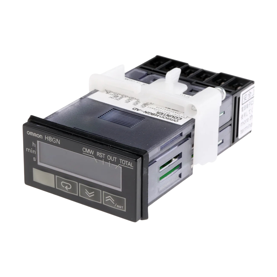
The model No. is expressed in 10 byte ASCII code. Empty bytes are space codes. Example: The model number for the H8GN is expressed as follows: H 8 G N - A D Communications buffer size The communications buffer size is expressed in 2 byte hexadecimal code, and read after being converted to 4 byte ASCII code. -
Page 25: Read Controller Status
2.3 Details of Services Read controller This service reads the run status of the controller. status Service request PDU Service response PDU Related Response informa status code tion (1) Run status Run status Description Status in which the count (timer) input can be accepted (error not generated when setup area is 0) Status in which the count (timer) input cannot be accepted (other than above) -
Page 26: Echoback Test
CHAPTER 2 CompoWay/F COMMUNICATIONS PROCEDURES Echoback test This service carries out the echoback test. Service request PDU Test data 0 to 23 Service response PDU Response Test data code 0 to 23 (1) Test data Set any test data within the range 0" to 23". Set a value for the test data within the ranges shown below according to the communications data length. -
Page 27: Operation Instructions
2.3 Details of Services Operation This service carries out reset, communications writing, multi SP , move to instructions protect level, move to setup area 1 and software reset. Service request PDU Instruc Related tion code informa tion Service response PDU Response code (1) Instruction code and related information... - Page 28 CHAPTER 2 CompoWay/F COMMUNICATIONS PROCEDURES (3) Description of operation instructions and precautions Communications writing Set the communications writing" parameter to ON: enabled" or OFF: disabled" according to related information. This instruction can be accepted at both setup areas 0 and 1. Reset The PV and/or total count value is reset according to the related value.
-
Page 29: Response Code List
2.4 Response Code List Response Code List At normal completion Error Response Name Description detection code priority 0000 Normal No errors were found. None completion At occurrence of error Error Response Name Description detection code priority 0401 Unsupported The service function for the relevant command command is not supported. - Page 30 CHAPTER 3 COMMUNICATIONS DATA CHAPTER CHAPTER 3 COMMUNICATIONS DATA This chapter lists the details of each of the communications data in the CompoWay/F communications procedures. Variable Area (setup range) List ..Status .
- Page 31 CHAPTER 3 COMMUNICATIONS DATA Variable Area (setup range) List The following table lists the variable areas. Items expressed in hexadeci mal in the Set (monitor) Value" column are the setting range. Values in parentheses ()" are the actual setting range. For details of variable areas that are described not in numerical values but by text, refer to the relevant parameter descriptions.
- Page 32 3.1 Variable Area (setup range) List Variable Address Item Set (monitor) Value Level type 0000 Set value H'00000000 to H'0000270F (0 to 9999) Operation Input mode at counter=incremental or decre mental H'FFFFFC19 to H'0000270F (-999 to 9999) Input mode at counter=individual or phase dif ferent input H'00000000 to H'0000270F (0 to 9999) Time range at timer=other than...
- Page 33 CHAPTER 3 COMMUNICATIONS DATA Variable Address Item Set (monitor) Value Level type 0000 Select function H'00000000(0): Counter Initial setting H'00000001(1): Timer 0001 Input mode H'00000000(0): Incremental H'00000001(1): Decremental H'00000002(2): Individual H'00000003(3): Phase difference 0002 Time range H'00000000(0): 0.000s to 9.999s H'00000001(1): 0.00s to 99.99s H'00000002(2):...
- Page 34 3.1 Variable Area (setup range) List Variable Address Item Set (monitor) Value Level type 0009 Decimal point H'00000000(0): Initial setting H'00000001(1): H'00000002(2): H'00000003(3): 000A Pre scale value H'00000001 to H'0000270F (0.001 to 9.999) 000B Input signal edge H'00000000(0): Rise edge H'00000001(1): Fall edge 000C...
- Page 35 CHAPTER 3 COMMUNICATIONS DATA Status The figure below shows the structure of the status data: Bit position PV underflow Spare Spare Spare CP1 (signal) input CP2 (gate) input Reset input Spare Spare Spare Spare Spare Output Spare Spare Spare...
- Page 36 3.2 Status Bit position Setup area Communications writing Spare Spare Spare Spare Spare Spare Spare Spare Spare Spare Spare Spare Spare Spare...
- Page 37 CHAPTER 3 COMMUNICATIONS DATA The following shows the status contents. Bit Description Bit position Bit position Status Status PV underflow *1 Not generated Generated Spare Spare Spare CP1 (signal) input *1 CP2 (gate) input *1 Reset input *1 Spare Spare Spare Spare Spare...
- Page 38 Sample Program The following sample program displays responses returned from the N88Basic H8GN on screen when command data is entered from the keyboard. Enter starting with the unit up to the number of elements as the command data. This sample program was created using N88BASIC...
- Page 39 CHAPTER 3 COMMUNICATIONS DATA 1440 Identification of end character (reading is continued if character is not end character) 1450 RDATA$=RDATA$+INPUT$ (LOC (1), #1) 1460 IF LEN (RDATA$)<2 THEN LOOP 1470 IF MID$ (RDATA$, LEN (RDATA$) -1, 1)<>CHR$ (3) THEN LOOP 1480 RESP$=MID$ (RDATA$, 2, LEN (RDATA$) -2) 1490...
- Page 40 WIRE switch to 2". Attach a terminator to H8GN. Sample ladder Read the PV of H8GN using sequence No. 600 send/receive with ASCII program conversion (response ON)" of the standard system protocol CompoWay /F Host" built into the Serial Communications Board.
- Page 41 "C0" "0001" "00" "0001" D01000 0007 No. of transmission words (D01000 to D01006) D01001 0001 Node No. of H8GN: 1 D01002 0101 CompoWay/F command: Variable area read D01003 000C No. of bytes transmitted: 12 D01004 C000 Variable type, read start address, bit position,...
- Page 42 APPENDIX APPENDIX ASCII List ....... . .
- Page 43 APPENDIX ASCII LIST (ANSI X 3.4 1986) SPACE Even parity ” & ’ < >...
- Page 44 NDEX Interface ......1 2, 1 3 Addresses ......Area definitions .
- Page 45 Revision History A manual revision code appears as a suffix to the catalog number on the front cover of the manual. Cat. No. M066 E1 1 Revision code The following table outlines the change made to the manual during each revision. Page numbers refer to previous version Revision code Data...
- Page 46 The Netherlands Tel: (31)2356-81-300/Fax: (31)2356-81-388 OMRON ELECTRONICS, LLC 1 East Commerce Drive, Schaumburg, IL 60173 U.S.A. Tel: (1)847-843-7900/Fax: (1)847-843-8568 OMRON ASIA PACIFIC PTE. LTD. 83 Clemenceau Avenue, #11-01, UE Square, Singapore 239920 Tel: (65)835-3011/Fax: (65)835-2711 OMRON CHINA CO. LTD. BEIJING OFFICE...