Advertisement
Table of Contents
- 1 Table of Contents
- 2 Warning Decal Placement
- 3 Important Precautions
- 4 Before You Begin
- 5 Part Identification Chart
- 6 Assembly
- 7 How to Use the Elliptical
- 8 How to Use the Console
- 9 Maintenance and Troubleshooting
- 10 Exercise Guidelines
- 11 Part List
- 12 Exploded Drawing
- 13 Ordering Replacement Parts
- 14 Recycling Information
- Download this manual
Model No. PFEL02921-INT.0
Serial No.
Write the serial number in the space
above for reference.
Serial
Number
Decal
CUSTOMER SERVICE
UNITED KINGDOM
Call: 0330 123 1045
From Ireland: 053 92 36102
Website: iconsupport.eu
E-mail: csuk@iconeurope.com
Write:
ICON Health & Fitness, Ltd.
Unit 4, Westgate Court
Silkwood Park
OSSETT
WF5 9TT
UNITED KINGDOM
AUSTRALIA
Call: 1800 993 770
E-mail: australiacc@iconfitness.com
Write:
ICON Health & Fitness, Inc.
PO Box 635
WINSTON HILLS NSW 2153
AUSTRALIA
CAUTION
Read all precautions and
instructions in this manual before
using this equipment. Keep this
manual for future reference.
USER'S MANUAL
iconeurope.com
Advertisement
Table of Contents

Related Manuals for Pro-Form SPORT E2.0


Summary of Contents for Pro-Form SPORT E2.0
- Page 1 Model No. PFEL02921-INT.0 Serial No. USER’S MANUAL Write the serial number in the space above for reference. Serial Number Decal CUSTOMER SERVICE UNITED KINGDOM Call: 0330 123 1045 From Ireland: 053 92 36102 Website: iconsupport.eu E-mail: csuk@iconeurope.com Write: ICON Health & Fitness, Ltd. Unit 4, Westgate Court Silkwood Park OSSETT...
-
Page 2: Table Of Contents
TABLE OF CONTENTS WARNING DECAL PLACEMENT ............. . .2 IMPORTANT PRECAUTIONS . -
Page 3: Important Precautions
IMPORTANT PRECAUTIONS WARNING: To reduce the risk of serious injury, read all important precautions and instructions in this manual and all warnings on your elliptical before using your elliptical. ICON assumes no responsibility for personal injury or property damage sustained by or through the use of this product. -
Page 4: Before You Begin
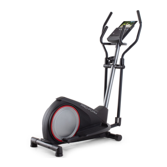
Thank you for selecting the new PROFORM manual. To help us assist you, note the product model ® SPORT E2.0 elliptical. The SPORT E2.0 elliptical number and serial number before contacting us. The provides a selection of features designed to make your model number and the location of the serial number workouts at home more effective and enjoyable. -
Page 5: Part Identification Chart
PART IDENTIFICATION CHART Use the drawings below to identify the small parts needed for assembly. The number in parentheses below each drawing is the key number of the part, from the PART LIST near the end of this manual. The number following the key number is the quantity needed for assembly. -
Page 6: Assembly
ASSEMBLY • Assembly requires two persons. • In addition to the included tool(s), assembly requires the following tools: • Place all parts in a cleared area and remove the one adjustable wrench packing materials. Do not dispose of the packing materials until you finish all assembly steps. - Page 7 3. Orient the Rear Stabilizer (9) as indicated by the sticker. While a second person lifts the rear of the Frame (1), attach the Rear Stabilizer (9) to the Frame with two M10 x 68mm Screws (34). 4. Orient the Upright (2) and the Top Shield (41) as shown.
- Page 8 5. See the inset drawing. Locate the wire tie (B) in the lower end of the Upright (2). Tie the wire tie to the Main Wire (73). Next, pull the upper end of the wire tie until the Main Wire is routed through the Upright.
- Page 9 7. While a second person holds the Console (23) near the Upright (2), plug the Main Wire (73) into the receptacle (C) on the Console. Tip: The wire connector should slide in easily and snap into place with an audible click. If it does not, turn the connector and try again.
- Page 10 9. Identify the Right Upper Body Arm (8). Slide an Upper Body Arm Cover (42) upward onto the Right Upper Body Arm (8). Next, insert the Right Upper Body Arm (8) into an Upper Body Leg (5). Tip: Have a second person hold the Upper Body Arm Cover (42) while you perform this action: Attach the Right Upper Body Arm (8) to the...
- Page 11 11. Orient an Upper Body Arm Spacer (47) as shown, and slide it onto the right side of the Pivot Axle (26). Next, slide the Right Upper Body Arm (8) onto the right side of the Pivot Axle (26). Repeat these actions on the other side of the elliptical.
- Page 12 13. Orient a Crank Arm Stud (32) as shown, and tighten it firmly into the Right Crank Arm (80). IMPORTANT: Make sure that the Crank Arm Stud is firmly tightened. Then, tighten an M6 x 8mm Set Screw (84) into the Right Crank Arm (80) and the Crank Arm Stud (32).
- Page 13 15. See assembly steps 4 and 5. Tighten the M10 x 20mm Screws (40) and the M10 Locknut (33). Then, press the Top Shield (41) into place. Next, apply a small amount of grease to an M6 Bolt Set (25). Hold the end of the Right Pedal Arm (12) inside the bracket on the right Upper Body Leg (5).
-
Page 14: How To Use The Elliptical
HOW TO USE THE ELLIPTICAL HOW TO PLUG IN THE POWER ADAPTER HOW TO MOVE THE ELLIPTICAL IMPORTANT: If the elliptical has been exposed to Due to the size and weight of the elliptical, moving cold temperatures, allow it to warm to room tem- it requires two persons. - Page 15 HOW TO EXERCISE ON THE ELLIPTICAL To dismount the elliptical, wait until the pedals (G) come to a complete stop. Note: The elliptical does To mount the elliptical, hold the handlebars (E) or the not have a free wheel; the pedals will continue to move until the flywheel stops.
-
Page 16: How To Use The Console
HOW TO USE THE CONSOLE CONSOLE DIAGRAM FEATURES OF THE CONSOLE With the iFit app, you can access a large and varied library of iFit video workouts, create your own work- The advanced console offers an array of features outs, track your workout results, and access many designed to make your workouts more effective and other features. - Page 17 HOW TO USE THE MANUAL MODE Pulse (BPM and heart symbol)—Your heart rate when you use a compatible heart rate monitor (see 1. Begin pedaling or press any button on the step 5). console to turn on the console. Resistance (RESIST)—The resistance level of the When you turn on the console, the display will turn pedals.
- Page 18 To customize the scan mode, first press the A compatible heart rate monitor is included with Display button repeatedly until the workout some models. If a heart rate monitor is included, information that you want to add to or remove from see THE HEART RATE MONITOR in this manual the scan cycle appears in the display.
- Page 19 HOW TO USE AN IFIT WORKOUT When a connection is established, the LED on the console will turn solid blue. The console offers access to a large and varied library 4. Select an iFit workout. of iFit workouts when you download the iFit app to your smart device and connect it to the console.
- Page 20 Note: The calorie goal shown in the workout HOW TO CONNECT YOUR HEART RATE MONITOR description is an estimate of the number of TO THE CONSOLE calories that you will burn during the workout. The actual number of calories that you burn The console is compatible with all Bluetooth Smart will depend on various factors, such as your heart rate monitors.
- Page 21 HOW TO CHANGE CONSOLE SETTINGS Total Time—The word TIME will appear in the display. The display will show the total number of 1. Select the settings mode. hours that the elliptical has been used. To select the settings mode, press the Settings button.
-
Page 22: Maintenance And Troubleshooting
MAINTENANCE AND TROUBLESHOOTING MAINTENANCE Note: For clarity, the right pedal disc is not shown in the drawing below. Regular maintenance is important for optimal performance and to reduce wear. Inspect and Locate the Reed Switch (53). Slightly loosen the properly tighten all parts each time the elliptical is M4 x 16mm Screw (52). - Page 23 HOW TO ADJUST THE DRIVE BELT Next, loosen the M8 x 22mm Screw (65), and turn the M10 x 60mm Bolt (62) until the Drive Belt (19) is tight. If you feel the pedals slip while you are pedaling, even when the resistance is adjusted to the highest level, the drive belt may need to be adjusted.
-
Page 24: Exercise Guidelines
EXERCISE GUIDELINES Aerobic Exercise—If your goal is to strengthen your WARNING: cardiovascular system, you must perform aerobic Before beginning this exercise, which is activity that requires large amounts or any exercise program, consult your physi- of oxygen for prolonged periods of time. For aerobic cian. -
Page 25: Part List
PART LIST Model No. PFEL02921-INT.0 R0521A Key No. Qty. Description Key No. Qty. Description Frame Upper Body Arm Spacer Upright Frame Spacer Left Shield Upper Body Arm Bushing Right Shield M8 x 41mm Bolt Upper Body Leg M10 x 22mm Washer Left Upper Body Arm M4 x 16mm Screw M10 x 77mm Bolt... -
Page 26: Exploded Drawing
EXPLODED DRAWING A Model No. PFEL02921-INT.0 R0521A 33 88... - Page 27 EXPLODED DRAWING B Model No. PFEL02921-INT.0 R0521A 40 83...
-
Page 28: Ordering Replacement Parts
ORDERING REPLACEMENT PARTS To order replacement parts, please see the front cover of this manual. To help us assist you, be prepared to provide the following information when contacting us: • the model number and serial number of the product (see the front cover of this manual) •...