Table of Contents
Advertisement
Quick Links
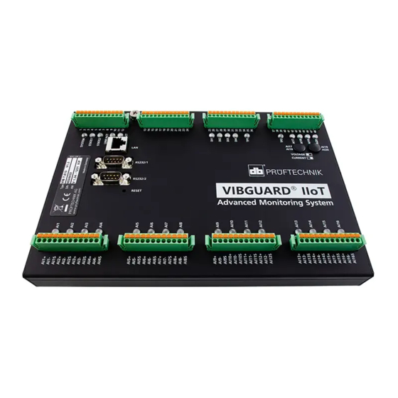
VIBGUARD
IIoT
Commissioning
Edition : 01.10.2018
Doc. no. : LIT 78.221.EN
Translation of the German manual
®
Type : VIB 7.800, VIB 7.810, VIB 7.811, VIB 7.815, VIB 7.820, VIB
7.825 Serial number and year of manufacture : see type plate
PRODUCER : Fluke Deutschland GmbH, Freisinger Str. 34, 85737
Ismaning, Germany, + 49 89 99616-0, www.pruftechnik.com
This manual is only intended for use with GL-
certified VIBGUARD CMS on wind turbines.
Advertisement
Table of Contents

Related Manuals for Fluke VIBGUARD IIoT


Summary of Contents for Fluke VIBGUARD IIoT
- Page 1 Edition : 01.10.2018 7.825 Serial number and year of manufacture : see type plate Doc. no. : LIT 78.221.EN PRODUCER : Fluke Deutschland GmbH, Freisinger Str. 34, 85737 Translation of the German manual Ismaning, Germany, + 49 89 99616-0, www.pruftechnik.com...
- Page 2 The absence of a marking does not however mean that names are not protected. VIBGUARD is a registered trademark of PRÜFTECHNIK AG. © Fluke Corporation. All rights reserved. Fluke Deutschland GmbH Freisinger Str. 34...
-
Page 3: Table Of Contents
3.2 Additional components 4 Visual inspection 4.1 RPM sensor function test 4.2 Cable routes and wiring 5 Connection test 5.1 Switching on VIBGUARD IIoT 5.2 Establishing a connection 5.3 Testing the connection 6 Network configuration 7 Sensor configuration 8 Sensor test 8.1 Sensor position... - Page 4 9 Process signals 10 Configuring Email transmission 10.1 Configuration 11 Sending a test email Edition: 10.2018...
-
Page 5: Prior To Starting
1.3 Abbreviations The following designations are considered equivalent in these instructions: Condition Monitoring System = CMS VIBGUARD IIoT Condition Monitoring System = VIBGUARD IIoT or System VIBGUARD IIoT system module = system module Sensors, cables, mountingadapters = measuring equipment. VIB 7.800, VIB 7.810, VIB 7.811, VIB 7.815, VIB 7.820, VIB 7.825 = VIB 7.8xx Current Linedrive = CLD 1.4 Service addresses... -
Page 6: Safety
Commissioning 2 Safety VIBGUARD IIoT was designed and built following careful selection of the harmonized norms to be complied with as well as other technical specifications. The system therefore corresponds to the state of the art and ensures the hig- hest degree of safety. -
Page 7: Safety Markings
2.3 Safety markings Please refer to the following figure for the safety markings on the VIBGUARD IIoT. The safety markings must be observed and must not be concealed or removed. For the variants that are installed in a control cabinet (VIB 7.xxx- PS), the safety labels must be attached at a suitable point in the control cabinet. -
Page 8: Type Plates
Commissioning 2.4 Type plates System module The type plate on the system module contains the following information: Type: Item number (VIB 7.820), hardware status (V1.3) of the System module. S/N: Serial number of the system module, 7 digits, starting with 95.. HW: Status (V 1.31), number (239), variant (LD = LineDrive) of the built-in board. -
Page 9: Information For The Operator
Ensure that the following requirements are complied with: The applicable legal and otherwise binding safety and accident prevention regulations as well as the general safety instructions and warnings must be adhered to and followed. Ensure that operating personnel work in a safety-conscious manner. VIBGUARD IIoT... -
Page 10: Information For Operating Personnel
Commissioning 2.6 Information for operating personnel Operating personnel qualifications Installation and disassembly may only be performed by a qualified specialist electrician. Commissioning and operation must only be performed by personnel who have been trained and authorized to do Personal protective equipment No protective equipment is required for installation, commissioning, normal operation and disassembly of the sys- tem. -
Page 11: Residual Hazards And Protective Measures
Commissioning 2.7 Residual hazards and protective measures VIBGUARD IIoT is verifiably safe assuming it is used as intended. The following damage may occur if operated incor- rectly or used improperly: Personal damage Damage to the system or to the machine... -
Page 12: Preliminary Remark
Commissioning 3 Preliminary remark This manual requires that you work with a common browser, e.g. Firefox (Mozilla) or Firefox Portable V15.x.x or hig- her. Firefox Portable can be found on your installation CD. With regard to the computer platform, this manual assumes that you are working with a PC running Windows 7. The interfaces of the various operating systems differ from each other. -
Page 13: Visual Inspection
Commissioning 4 Visual inspection EveryStartupbegins with a visual inspection of the sensors that are installed. In this regard, it is necessary to check that the accelerometers are firmly screwed in, the cables are undamaged, and the RPM sensor is correctly aligned with the trigger mark. -
Page 14: Connection Test
The network cable on the VIBGUARD IIoT is not suitable for a direct connection between the notebook and VIBGUARD IIoT as it is wired one to one. A direct connection is only possible with a crossed patch cable (Cross cable). - Page 15 Commissioning Click on <General Status Information>. This call triggers a command that reads and displays various CMS sys- tem parameters. In the "System Status" block, compare the serial number in the "Serial Number:" line with the delivery docu- mentation. The serial number has 7 digits and starts with 95xxxxx, e.g. 9515054. If the numbers are identical, this means you were able to connect to the correct system and the connection test was successful.
-
Page 16: Network Configuration
Commissioning 6 Network configuration Upon delivery, a standard network configuration is stored in every VIBGUARD IIoT to allow access to the CMS on- site ("Connection test" on page 14). If the CMS is integrated in an existing network, the network administrator will provide you with the net- work parameters to be set. -
Page 17: Sensor Configuration
The settings of the sensor parameters are implemented via special configuration pages. These pages are part of the user interface in the VIBGUARD IIoT. VIBGUARD IIoT starts the standard startup measurement configuration after the power supply has been switched on. This configuration is adapted to the specific system during startup. - Page 18 The page loads the data from the VIBGUARD IIoT and displays the current configuration of the measuring channels and the entries in the machine tree (Machine Tree) after startup. There are three buttons at the top of the page. These buttons can be used to send commands to VIBGUARD IIoT (see further below).
-
Page 19: Sensor Test
Commissioning 8 Sensor test Using the overview page with all online readings ('Display Input Storage Location Values'), check whether the acce- lerometers are properly wired and working correctly. Connect to the CMS via the browser. Enter the login details. The homepage appears. Select the following link on the homepage: <Online Visualization>... -
Page 20: Sensor Position
It can take a few moments for the status LED to respond. This is because the CMS regularly performs over- all value calculations in the context of the measurement configuration. Reconnect the cable plug to the sensor and wait until the status LED displays the OK state (green) again. Repeat these steps for all sensors. VIBGUARD IIoT... - Page 21 Commissioning 9 Process signals On the overview page of all online values ("Sensor test" on page 19), check whether the values of the process signals match the values from the system controller. The assignment of the channels is derived from the sensor con- figuration page ("Sensor configuration"...
- Page 22 Click on <Email Configuration> in the “Configuration” field. The menu with the email parameters appears. The menu is split into three sections: Email configuration display: Configure sender data Account configuration: Create an email account Email configuration: Configure Email Set email parameters Sender VIBGUARD IIoT...
- Page 23 Commissioning Click on <Edit> under “Email configuration display” to open the input mask for the Sender data. Enter a Name in the “Sender Name” field. The name can be chosen arbitrarily, but it should have a reference to the monitored system. Enter an Email address in the “Email Address”...
- Page 24 Email Subject: Email subject line; this should have a meaningful reference to the content. Attachment type: If you want the email to contain an attachment, select whether a specific file ("File") or all measurement data ("All Measurement Data") is to be sent. VIBGUARD IIoT...
- Page 25 Commissioning Set the type to “None” for the Test transmission. Attachment file: Enter the file that is to be sent as an attachment here. To conclude, click on <Save Settings> and confirm the following message with <OK>. The "Email configuration" section now contains another field for entering the recipient data " Recipient Name". Click on <Add New>...
- Page 26 Commissioning 11 Sending a test email The CMS processes the programmed measurement tasks autonomously. The stored measurement data is pro- cessed on the system, evaluated and made available for transmission via the data network. Data is transmitted to an external service center at regular intervals for further analyses and condition diagnoses. Data transmission is carried out in the course of system and email configuration.
- Page 27 A confirmation page provides the response from the SMTP server. Note the outcome in the setup log. In the event of an error, check the email configuration and ask the operator or administrator if the SMTP server is working properly. Arrange for an inspection if necessary. VIBGUARD IIoT...
- Page 28 Printed in Germany LIT 78.221.EN.10.2018 Fluke Deutschland GmbH Freisinger Str. 34 85737 Ismaning, Germany + 49 89 99616-0 www.pruftechnik.com Productive Maintenance Technology...