Table of Contents
Advertisement
CEILING & FLOOR TYPE AIR CONDITIONER
12,000 - 60,000 Btu/h
MCXE Series 50 Hz
Cooling Only Model
Series 5 Model
MCXE12SB50AA / TTKE12SB5EAA
MCXE18SB50AA / TTKE18SB5EAA
MCXE24SB50AA / TTKE24SB5EAA
MCXE30SB50AA / TTKE30SB5EAA
MCXE36SB50AA / TTKE36SB5EAA
MCXE36SB50AA / TTKE36SD5EAA
MCXE42SB50AA / TTKE42SD5EAA
Only qualified personnel should install and service the equipment. The installation, starting up, and servicing of
heating, ventilating, and air-conditioning equipment can be hazardous and requires specific knowledge and training.
Improperly installed, adjusted or altered equipment by an unqualified pers on could result in death or serious injury.
When working on the equipment, observe all precautions in the literature and on the tags, stickers, and labels that are
attached to the equipment.
May 2020 (Rev.B)
Standard Model
MCXE48SB00AA / TTKE48SD0EAA
MCXE60SB00AA / TTKE60SD0EAA
SAFETY WARNING
MCXE-IOM
690882610001
Confidential and proprietary Trane information
R32
Advertisement
Table of Contents

Related Manuals for Trane MCXE Series


Summary of Contents for Trane MCXE Series
- Page 1 CEILING & FLOOR TYPE AIR CONDITIONER 12,000 - 60,000 Btu/h MCXE Series 50 Hz Cooling Only Model Series 5 Model Standard Model MCXE12SB50AA / TTKE12SB5EAA MCXE48SB00AA / TTKE48SD0EAA MCXE18SB50AA / TTKE18SB5EAA MCXE60SB00AA / TTKE60SD0EAA MCXE24SB50AA / TTKE24SB5EAA MCXE30SB50AA / TTKE30SB5EAA...
- Page 2 MCXE-IOM...
- Page 3 MCXE-IOM...
- Page 4 • • • • • • • • • • • • • • • • • • • • • • • • • • • • • • • • • • • • • • • • •...
- Page 5 • (Btu/h) (m ) 12,000 18,000 24,000 30,000 36,000 42,000 48,000 60,000 Correct Disposal of this Product (Waste Electrical & Electronic Equipment) When disposing of this appliance, you have the following options: Dispose of the appliance at designated municipal electronic waste collection facility. When buying a new appliance, the retailer will take back the old appliance free of charge.
- Page 6 MANUAL OPERATION TIMER DEF./FAN ALARM Cooling Mode Dry Mode Room 17°C - 32°C 10°C - 32°C Temperature 18°C - 43°C 11°C - 43°C -7°C - 43°C Outdoor 18°C - 43°C (For models with low-temp cooling systems) Temperature 18°C - 52°C 18°C - 52°C (For special tropical models) (For special tropical models)
- Page 7 MCXE-IOM...
- Page 8 S1&S2(P&Q&E) MCXE-IOM...
- Page 9 Indoor Unit / Fan Coil Unit Outdoor Unit / Condensing Unit MCXE-IOM...
- Page 10 MANUAL OPERATION TIMER DEF./FAN ALARM MCXE-IOM...
- Page 11 1200 1565 1565 MCXE-IOM...
- Page 12 MCXE-IOM...
- Page 13 12K~18K 1068 1285 1200 30K~42K 1650 1565 48K~60K 1650 1565 MCXE-IOM...
- Page 14 ½H ½ MCXE-IOM...
- Page 15 • • • MCXE-IOM...
- Page 16 • • • • • • MCXE-IOM...
- Page 17 • • • • • • • • • • • MCXE-IOM...
- Page 18 • • • • • • MCXE-IOM...
- Page 19 MCXE-IOM...
- Page 20 MCXE-IOM...
- Page 21 > 3 1.00 > 6 1.50 > 10 2.50 > 16 4.00 > 25 • 6.00 > 32 • 12k-18k 1 Phase 208-240V 25/20 30-36k 42-60k 1 Phase 1 Phase 3 Phase 3 Phase 208-240V 380-420V 208-240V 380-420V 32/25 50/40 25/20 32/25 MCXE-IOM...
- Page 22 55 mm 120 mm 18.5 mm 46 mm 123 mm 83.5 mm 62 mm Remote Indoor Control Unit MCXE-IOM...
- Page 23 SWING TIMER SLEEP SWING FOLLOW SELF SHORT TURBO CLEAN • • • MCXE-IOM...
- Page 24 Transmission Indicator ON/OFF display Lock Indicator Battery display MODE display Temperature/Timer display • • TIMER ON display ( ) Fan speed display TIMER OFF display ( ) Silence feature display Follow me feature display Sleep mode display MCXE-IOM...
- Page 25 • • MCXE-IOM...
- Page 26 3sec 3sec MCXE-IOM...
- Page 27 • • • SWING TIMER SLEEP • SWING FOLLOW SELF SHORT TURBO CLEAN • • • SWING • • • • SWING • • • • MCXE-IOM...
- Page 28 Copy/ Swing Timer Day off/Del Confirm Back/Turbo Follow me Mode Fan speed (Lock) (Confirm) MCXE-IOM...
- Page 29 Remote Indoor Control Unit MCXE-IOM...
- Page 30 MCXE-IOM...
- Page 31 Timer Timer Timer Fan speed (Lock) Mode Indoor Unit Copy/ Follow me MCXE-IOM...
- Page 32 Swing Fan speed (Lock) Swing Swing Timer Copy/ Back/Turbo Follow me ℃ ℉ Back/Turbo MCXE-IOM...
- Page 33 Timer Confirm Confirm Confirm Confirm Confirm Confirm Confirm Confirm Confirm Confirm Confirm Timer Confirm Confirm Confirm Confirm Confirm Confirm MCXE-IOM...
- Page 34 Confirm Confirm Timer Copy/ Follow me • Timer • Copy/ Confirm Follow me Confirm Day off/Del Confirm Confirm Back/Turbo Back/Turbo • • MCXE-IOM...
- Page 35 Confirm Confirm Confirm Confirm Day off/Del MCXE-IOM...
- Page 36 Series 5 Model MCXE12SB50AA MCXE18SB50AA ENC1 ADJUSTMENT ENC1 CODE 36~53 54~71 72~90 91~105 106~120 121~140 141~160 POWER MCXE MCXE-IOM...
- Page 37 Series 5 Model Standard Model MCXE24SB50AA MCXE48SB00AA MCXE30SB50AA MCXE60SB00AA MCXE36SB50AA MCXE42SB50AA ENC1 ADJUSTMENT ENC1 CODE 36~53 54~71 72~90 91~105 106~120 121~140 141~160 POWER MCXE MCXE-IOM...
- Page 38 Series 5 Model TTKE12SB5EAA TTKE18SB5EAA MCXE-IOM...
- Page 39 Series 5 Model TTKE24SB5EAA MCXE-IOM...
- Page 40 Series 5 Model TTKE30SB5EAA MCXE-IOM...
- Page 41 Series 5 Model TTKE36SB5EAA MCXE-IOM...
- Page 42 Series 5 Model Standard Model TTKE36SD5EAA TTKE48SD0EAA TTKE42SD5EAA TTKE60SD0EAA MCXE-IOM...
- Page 43 LED1 LED2 LED3 Phase sequence 36-60k 380V/3Phase only 36-60k Stop phase (B,C) 380V/3Phase only Stop phase (A) 36-60k 380V/3Phase only Low pressure protect 36-60k Current protect 36-60k T3 open, short circuit trouble 36-60k T4 open, short citcuit trouble 36-60k (high pressure protect) Condensor high pressure protect 36-60k MCXE-IOM...
- Page 44 • • • • • • • MANUAL OPERATION TIMER DEF./FAN ALARM MCXE-IOM...
- Page 45 MCXE-IOM...
- Page 46 • • • • • • • • • • • • • MCXE-IOM...
- Page 47 MCXE-IOM...
- Page 48 MCXE-IOM...
- Page 49 MCXE-IOM...
- Page 50 Owner’s Manual & Installation Manual IRIS (Fix Speed) CEILING & FLOOR TYPE AIR CONDITIONER 12,000 - 60,000 Btu/h MCXE Series 50 Hz Cooling Only Model Series 5 Model Standard Model MCXE12SB50AA / TTKE12SB5EAA MCXE48SB00AA / TTKE48SD0EAA MCXE18SB50AA / TTKE18SB5EAA MCXE60SB00AA / TTKE60SD0EAA...
-
Page 51: General Information
The warranty is void if the equipment is modified or procedures should be performed in the sequence that they repaired without the written approval of The Trane Company, appear in this manual. if the operating limits are exceeded or if the control system For installing the unit to operate properly and reliably, it must or the electrical wiring is modified. -
Page 52: Table Of Contents
Contents General Information Safety Precaution Unit Specifications and Features Installation Summary Accessories System Appearance Indoor Unit Installation Outdoor Unit Installation Refrigerant Piping Connection Gas Leakage Inspection Air Evacuation and Refrigerant Charge Electrical Installation Remote Controller Installation Wireless Remote Controller Wired Remote Controller Wiring Diagram Care and Maintenance Troubleshooting... -
Page 53: Safety Precaution
System Precautions Please read and follow the instructions and Refrigerant R32 is environmentally friendly. warnings in the manual carefully before High cooling efficiency and ignite at low installation or mantenance air conditioner. rates. WARNING ELECTRICAL WARNINGS This symbol indicates the possibility of death or serious injury. •... - Page 54 System Precautions WARNINGS FOR PRODUCT INSTALLATION WARNINGS FOR USING R32 REFRIGERANT • Install the unit in a firm location that can support the unit’s weight. If the • When flammable refrigerant are employed, appliance shall be stored in a wall- chosen location cannot support the unit’s weight, or the installation is ventilated area where the room size corresponds to the room area as specific not done properly, the unit may drop and cause serious injury and damage.
-
Page 55: Unit Specifications And Features
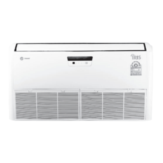
Unit Specifications and Features Indoor unit display MANUAL OPERATION TIMER DEF./FAN ALARM Installation part Infrared receiver OPERATION : This lamp lights when the system is operating. TIMER : This lamp lights when the system is being controlled by timer DEF / FAN : This lamp lights when the system is in fan mode. -
Page 56: Installation Summary
Installation Summary Install the indoor unit Install the drainpipe Install the outdoor unit Evacuate the refrigeration Connect the wires Connect the refrigerant system pipes Perform a test run MCXE-IOM... -
Page 57: Accessories
S1&S2(P&Q&E) (some models) NOTE : * Wireless remote controller and wired controller are sold seperate from air conditioning unit. (Please contact to Trane sales representative to select remote controller model.) ** Noise filter for electronic system. MCXE-IOM... -
Page 58: System Appearance
* Wireless remote controller and wired controller are sold seperate from air conditioning unit. (Please contact to Trane sales representative to select remote controller model.) NOTE ON ILLUSTRATIONS Illustrations in this manual are for explanatory purposes. The actual shape of your indoor unit may be slightly different. -
Page 59: Indoor Unit Installation
Indoor Unit Installation Step 1: Select installation location Enough room exists for installation and maintenance. Enough room exists for the connecting the pipe and drainpipe. The ceiling is horizontal and its structure can sustain the weight of the indoor unit. The air inlet and outlet are not blocked. - Page 60 Indoor Unit Installation Ceiling Installation Step 2: Unit installation Screw Nut Hanging Arms Hanging Screw Bolt Wall CAUTION Outdoor Indoor Hanging Arms re to Hanging arm distance Model (Btu/h) D (mm) Note : MCXE-IOM...
- Page 61 Indoor Unit Installation Step 3: Indoor Drainpipe Installation Cover the drainpipe with heat insulation to prevent condensation and leakage. Attach the mouth of the drain hose to the unit’s outlet pipe. Sheath the mouth of the hose and clip it firmly with a pipe clasp. Drain hose 1-1.5m (39-59”)
- Page 62 Indoor Unit Installation Dimensional Data Model Length of A Length of B Length of C Length of D Length of E (Btu/h) (mm) (mm) (mm) (mm) (mm) 12K~18K 1068 1285 1200 30K~42K 1650 1565 48K~60K 1650 1565 MCXE-IOM...
-
Page 63: Outdoor Unit Installation
Outdoor Unit Installation Unit Installation Dimensional Data Should be mounted on a concrete platform. At least 100 mm. height and mounted on a concrete plateform with bolts. The base should strong enough to support weight and vibration. In case of installing the machine on the roof make sure the roof can support the weight. -
Page 64: Refrigerant Piping Connection
Refrigerant Piping Connection Flaring Procedure Cut the copper tube to the recommend to cut aprox. 30-50 cm longer than the tubing length you estimate. Hold each tube downward when cutting, remove burrs at the end of the copper tube with a tube reamer or file. This process is important and should be done carefully Tighten the flare nut to the specified tightening torque with to make a good flare. - Page 65 Refrigerant Piping Connection Indoor unit is installed higher than the outdoor unit Anexample of incorrect interconnection pipeline. • • • • • Outdoor unit is installed higher than the indoor unit The maximum lenght and drop height base on models •...
-
Page 66: Gas Leakage Inspection
Gas Leakage Inspection Gas Leakage Inspection Caution After the refrigerant pipe system is complete, It is necessary • Do not fully open nitrogen valve to 400 psig because valve to check gas leakage. Inspecting gas leakage should be done may be damage. with special precaution. -
Page 67: Air Evacuation And Refrigerant Charge
Air Evacuation and Refrigerant Charge Evacuation How to fill up refrigerant Air and humidity and the enemy of the air-conditioning system Normally, this needs to be done immediately after air evacuation because humidity well react with R32 refrigerant and turns into per the following steps. - Page 68 Air Evacuation and Refrigerant Charge When the interconnecting line is longer than 7.5 m, additional charging is necessary. The refrigerant should be charged from the service port on the outdoor unit’s low pressure valve. The additional refrigerant to be charged can be the following table belows.
-
Page 69: Electrical Installation
Electrical Installation Wiring Electric wire and ground wire must comply with each country’s or regional’s regulation. Check the unit nameplate for electrical rating. Make sure that the wiring is according to local codes and wiring system diagram. A separate power supply disconnect and a circuit breaker for overcurrent protection should be provided inthe external power supply line. Always connect ground wire to condensing unit every time to prevent an electric shock in case of an electric leakage. - Page 70 Electrical Installation Electric Wiring Connection You must first choose the right cable size. Be sure to use H07RN-F cables. See wiring diagram. Slipover electric wire at the end. After connect electric wire, check whether all screws are firmly tightened. Minimum Cross-Sectional Area of Power ( GOOD ) ( BAD ) and Signal Cables (For reference)
-
Page 71: Remote Controller Installation
Remote Controller Installation Remote Controller Installation Do not place the remote control near heat sources or expose to the direct rays of the sun. Do not expose the remote control to the indoor unit’s supply air stream. Do not place in a confined space. Attach the remote control holder as shown below. -
Page 72: Wireless Remote Controller
Wireless Remote Controller Function Buttons Model : RG66A1(B)/BGEF ON/OFF Selects fan speeds in the following order: Turn the unit ON or OFF AUTO HIGH MODE Scrolls through operation modes as follows: AUTO COOL HEAT TEMP Increases temperature in 1 SLEEP Max. - Page 73 Wireless Remote Controller Remote Controller LCD Screen Indicators Transmission Indicator Lights up when remote ON/OFF display sends signal to indoor unit Appears when the unit is turned ON, and disappears when the unit is turned OFF. Lock Indicator Lights up when Lock feature is activated Battery display Low battery detection MODE display...
- Page 74 Wireless Remote Controller AUTO Operation DRY Operation In AUTO mode, the unit will automatically select the COOL, Press the MODE button to select DRY mode. FAN, HEAT(Not respond) or DRY mode base on the set Set your desired temperature using the Temp temperature.
- Page 75 Wireless Remote Controller Setting the TIMER function TIMER ON function TIMER OFF function Press the TIMER button, the TIMER ON indicator “ ” Press the TIMER button, the TIMER OFF indicator “ ” displays and flashes. By default, the last time period that displays and flashes.
- Page 76 Wireless Remote Controller SLEEP Function The SLEEP function is used to decrease eneygy use while you sleep (and don’t need the same temperature settings to stay comfortavle). This function can only be activate via remote control. NOTE: Not available in FAN or DRY mode. FOLLOW ME Function SWING TIMER...
-
Page 77: Wired Remote Controller
Wired Remote Controller Function Buttons Copy/ Swing Timer Day off/Del Confirm Back/Turbo Follow me Mode Fan speed (Lock) 1. Mode 6. Timer 2. Power 7. Day Off/Del 3. Adjust 8. Copy/Follow me 4. Fan Speed 9. Back/Turbo 5. Swing 10. Confirm MCXE-IOM... - Page 78 Wired Remote Controller 1. Dimensional 5. Fasten the wired remote controller back plate For surface mounting, fasten the back plate on the wall with the 3 screws (M4x20) and plugs. 6. Wire the indoor unit: There are three methods 2. Wiring diagram Wiring connection diagram Insert of the 1) from the rear.
- Page 79 Wired Remote Controller Remote Controller LCD Screen Indicators 1. Operation mode indicator 9. °C indicator 2. Fan speed indicator 10. Temperature display 3. Left-right swing indicator 11. Lock indicator 4. Up-down swing indicator 12. Room temperature indicator 5. Panel function indicator 13.
- Page 80 Wired Remote Controller Set the current day and time Timer Press TIMER for 3 seconds or more. The timer displays flashes. Date setting is complete and the time setting is ready after Timer pressing TIMER or if nothing is pressed in 10 seconds. ex.Monday AM 11:20 Timer To start/stop operation...
- Page 81 Wired Remote Controller Child lock function Swing function Up-Down swing Swing Fan speed (Lock) Press the Swing button to start up-down swing function. Press it again to stop. Press LOCK for 3 seconds to activate the CHILD LOCK feature and lock all buttons on When the Up-Down swing function is activated, the wired controller.
- Page 82 Wired Remote Controller TIMER FUNCTIONS IMPORTANT: To set the On or Off TIMER and FAN speeds. Timer No display Confirm Confirm CONFIRM. Confirm Confirm NOTE: CONFIRM. Weekly timer setting Confirm NOTE: Confirm Timer Confirm press CONFIRM. Confirm NOTE: NOTE: MCXE-IOM...
- Page 83 Wired Remote Controller TIMER FUNCTIONS WEEKLY timer operation Copy out the setting in one day into the other day. To start A scheduled event, made once, can be copied to another day of the week. The scheduled events of the selected day Press Timer to select the , and then the timer starts of the week will be copied.
- Page 84 Wired Remote Controller TIMER FUNCTIONS Delete the time scale in one day. FAULT ALARM HANDING If the system does not properly operate except in the aforementioned cases or the aforementioned malfunctions During the weekly timer setting, Confirm are evident, investigate the system according to the following MALFUNCTION DISPLAY Communication error between wired...
- Page 85 Wiring Diagram Indoor Unit Series 5 Model MCXE12SB50AA MCXE18SB50AA ENC1 ADJUSTMENT ENC1 CODE POWER 36~53 54~71 72~90 91~105 106~120 121~140 141~160 MCXE MCXE-IOM...
- Page 86 Wiring Diagram Indoor Unit Series 5 Model Standard Model MCXE24SB50AA MCXE48SB00AA MCXE30SB50AA MCXE60SB00AA MCXE36SB50AA MCXE42SB50AA ENC1 ADJUSTMENT ENC1 CODE POWER 36~53 54~71 72~90 91~105 106~120 121~140 141~160 MCXE MCXE-IOM...
-
Page 87: Wiring Diagram
Wiring Diagram Outdoor Unit Series 5 Model TTKE12SB5EAA TTKE18SB5EAA MCXE-IOM... - Page 88 Wiring Diagram Outdoor Unit Series 5 Model TTKE24SB5EAA MCXE-IOM...
- Page 89 Wiring Diagram Outdoor Unit Series 5 Model TTKE30SB5EAA MCXE-IOM...
- Page 90 Wiring Diagram Outdoor Unit Series 5 Model TTKE36SB5EAA MCXE-IOM...
- Page 91 Wiring Diagram Outdoor Unit Series 5 Model Standard Model TTKE36SD5EAA TTKE48SD0EAA TTKE42SD5EAA TTKE60SD0EAA MCXE-IOM...
- Page 92 Wiring Diagram Outdoor Unit PCB diagnostic alarm table Mulfunction LED1 LED2 LED3 Model 36-60k Phase sequence Blink 380V/3Phase only 36-60k Stop phase (B,C) Blink 380V/3Phase only 36-60k Stop phase (A) 380V/3Phase only Low pressure protect Blink Blink 36-60k Current protect Blink 36-60k T3 open, short circuit trouble...
-
Page 93: Care And Maintenance
Care and Maintenance Indoor Unit and Air Filter Cleaning 1. Push latch at air inlet grille and insert a screwdriver to remove screw. Detach the grille from the main unit by holding the grille at a 90° angle, lifting it up slightly. 3. - Page 94 Care and Maintenance Maintenance : Long Periods of Non-Use Maintenance : Pre-Season Inspection If you plan not to use your air conditioner for an extended period After long periods of non-use, or before periods of frequent of time, do the following: use, do the following: Clean all filters Turn on FAN function...
-
Page 95: Troubleshooting
Troubleshooting SAFETY PRECAUTIONS If any of the following conditions occurs, turn off your unit immediately! • The power cord is damaged or abnormally warm • You smell a burning odor • The unit emits loud or abnormal sounds • A power fuse blows or the circuit breaker frequently trips •... - Page 96 Troubleshooting Troubleshooting When troubles occur, please check the following points before contacting a repair company. Symptom Cause Action recommended Compressor not start up, Main power supply switched off. Switched on main power supply. have sound. No fuse or fuse break. Replace fuse.
- Page 97 Troubleshooting Symptom Cause Action recommended Compressor working Low refrigerant. Check leak and recharge refrigerant. all time. Controller is dirty. Clean or replace controller. The room is too large or poor Replace new air-conditioning to fits insulation. the room space or fix insulation. Interconnection piping is too small.
- Page 98 MEMO MCXE-IOM...
- Page 99 MEMO MCXE-IOM...
- Page 100 For more information, please visit trane.com or tranetechnologies.com. Trane has a policy of continuous product and product data improvement and reserves the right to change design and specifications without notice. We are committed to using environmentally conscious print practices.