Table of Contents
Advertisement
Application
The F4-XPM series expansion I/O modules can serve
in one of two capacities depending on where they are
installed in the system. When installed on the Sensor/
Actuator (SA) Bus of an equipment controller, an XPM
expands the input and output interfaces that can be
used with that equipment controller. When installed on
the Field Controller (FC) Bus of a FX-SNC, an XPM can be
used as I/O point multiplexors to support monitoring and
control from a FX-SNC. The point multiplexor can also
be useful for sharing points between other equipment
controllers on the FC Bus using peer-to-peer connectivity.
XPMs operate on an RS-485 BACnet MS/TP Bus and are
BACnet Testing Laboratory (BTL) listed and certified to the
BACnet Smart Actuator (B-SA) profile.
Communications Protocols
The XPM expansion modules can communicate using
BACnet MS/TP, or wireless Zigbee
Wireless Field Bus Router (on the FC Bus only). By default,
the XPM expansion modules communicate using the
BACnet MS/TP protocol. The BACnet protocol is a standard
for ANSI, ASHRAE, and the International Standards
Organization (ISO) for building controls. To configure
these expansion modules in a wireless application
installation, see
Configuring wireless
Note: Using Controller Configuration Tool (CCT)
10.1 and later, FX equipment Controllers can be
configured to communicate using either the BACnet
MS/TP or the N2 field bus networking protocol.
The operation of an XPM on the SA Bus of an
equipment controller is not affected by the selection
of the BACnet MS/TP or the N2 protocol in the host
controller.
North American Emissions Compliance
United States
This equipment has been tested and found to comply
with the limits for a Class A digital device pursuant to
Part 15 of the FCC Rules. These limits are designed
to provide reasonable protection against harmful
interference when this equipment is operated in a
commercial environment. This equipment generates,
uses, and can radiate radio frequency energy and, if not
installed and used in accordance with the instruction
manual, may cause harmful interference to radio
communications. Operation of this equipment in a
residential area may cause harmful interference, in which
case the users will be required to correct the interference
at their own expense.
F4-XPM Expansion Modules Installation Guide
using a ZFR/ZFR Pro
®
communications.
Canada
This Class (A) digital apparatus meets all the
requirements of the Canadian Interference-Causing
Equipment Regulations.
Cet appareil numérique de la Classe (A) respecte toutes
les exigences du Règlement sur le matériel brouilleur du
Canada.
Installation
Observe the following guidelines when installing an XPM
expansion module:
• To minimize vibration and shock damage transport the
expansion module in the original container.
• Verify that all parts shipped with the expansion module.
• Do not drop the expansion module or subject it to
physical shock.
Parts included
• One XPM expansion module with removable terminal
blocks (Input/Output, Power and SA bus terminal
blocks)
• One installation guide sheet
Materials and special tools needed
• Three fasteners appropriate for the mounting surface
(M4 screws or #8 screws)
• One 20 cm (8 in.) or longer piece of 35 mm DIN rail and
appropriate hardware for DIN rail mount (only)
• Small straight-blade (1/8 in. or 3.2 mm) or Philips #2
screwdriver for securing wires in the terminal blocks
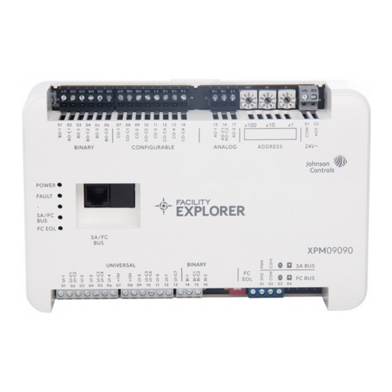
Physical features
The following figures display the physical features of XPM
expansion modules, and the accompanying table provides
a description of the physical features and a reference to
further information where required.
*241014302155-*
F4-XPM04060, F4-XPM09090, F4-XPM18000
Part No. 24-10143-02155 Rev -
2020-11-11
(Barcode for factory use only)
Advertisement
Table of Contents

Related Manuals for Johnson Controls F4-XPM Series


Summary of Contents for Johnson Controls F4-XPM Series
- Page 1 2020-11-11 Application Canada This Class (A) digital apparatus meets all the The F4-XPM series expansion I/O modules can serve requirements of the Canadian Interference-Causing in one of two capacities depending on where they are Equipment Regulations. installed in the system. When installed on the Sensor/ Actuator (SA) Bus of an equipment controller, an XPM Cet appareil numérique de la Classe (A) respecte toutes...
- Page 2 Figure 1: XPM09090 and XPM04060 Physical Features Table 1: Physical features of expansion modules (XPM04060 model shown) Physical Feature: Description and References End-of-Line (EOL) Switch. See Setting the End-of-Line (EOL) switch. Binary Input (BI) Terminal Block: White terminals. See Table 2. Universal Input (UI) Terminal Block: Only present on XPM09090 and XPM04060 models.
-
Page 3: Wall Mount Applications
DIN rail mount applications Figure 3: Expansion Module mounting position About this task: To mount a XPM expansion module horizontally on a 35 mm DIN rail (recommended method), complete the following steps: Securely mount a 20 cm (8 in.) or longer section of 35 mm DIN rail horizontal and centered in the desired space so that the expansion module mounts in the horizontal position. - Page 4 Important: Do not exceed the expansion module electrical ratings. Exceeding the electrical ratings CAUTION can result in permanent damage to the expansion module and void any warranty. Risk of Electric Shock: Important: Use copper conductors only. Make all wiring in accordance with local, national, and Disconnect the power supply before making electrical regional regulations.
- Page 5 Analog Input - Resistive Mode (0–600k ohm) (Inputs) Internal 12 V. 15k ohm pull up Qualified Sensors: 0-2k ohm potentiometer, RTD (1k Nickel See Guideline A in Table 3. [Johnson Controls sensor], 1k Platinum, and A99B Silicon ® Temperature Sensor) Negative Temperature Coefficient (NTC) Sensor...
- Page 6 Table 2: I/O terminal block functions, functions, ratings, requirements, and cable guidelines Terminal Determine wire size and Terminal Block label Function, ratings, requirements label maximum cable length Analog Output - Voltage Mode (0–10 VDC) 10 VDC maximum output voltage See Guideline A in Table 3. 10 mA maximum output current Required an external load of 1,000 ohm or more.
- Page 7 Cable and wire length guidelines Table 3 defines cable length guidelines for the various wire sizes that may be used for wiring low-voltage (<30 V) input and outputs. The required wire sizes and lengths for high-voltage (>30 V) Relay Outputs are determined by the load connected to the relay, and local, national or regional electrical codes.
- Page 8 Communications bus and supply power • All SA and FC bus cables, regardless of wire size, should be twisted, insulated, stranded copper wire. wiring guidelines • Shielded cable is strongly recommended for all SA and Table 4 provides information about the functions, ratings, FC bus cables.
- Page 9 Termination diagrams A set of Johnson Controls termination diagrams provides details for wiring inputs and outputs to the expansion modules. See the figures in this section for the applicable termination diagrams. Note: References to the analog output apply to the XPM09090 model only.
- Page 10 Table 5: Termination details Type of field Type of Input/ Termination diagrams device Output Current Input - External Source (Isolated) Current Input - Internal Source (2- wire) Current Input - Internal Source (3 wire) Current Input - External Source (in Loop) Feedback from EPP-1000...
- Page 11 Table 5: Termination details Type of field Type of Input/ Termination diagrams device Output Dry Contact UI or BI (Binary Input) 0–10 VDC Output to Actuator CO or AO (External Source) 0–10 VDC Output to Actuator CO or AO (Internal Source) Current Output CO or AO 24 VAC Triac...
- Page 12 Table 5: Termination details Type of field Type of Input/ Termination diagrams device Output Analog Output (Current) 4–20 mA Output to Actuator 4–20 mA Output to Actuator Incremental Control to Actuator (Switch Low, Externally Sourced) 24 VAC Binary Output (Switch Low, Externally Sourced) F4-XPM Expansion Modules Installation Guide...
- Page 13 Table 5: Termination details Type of field Type of Input/ Termination diagrams device Output 24 VAC Binary Output (Switch High, Externally Sourced) Incremental Control to Actuator (Switch High, Externally Sourced) F4-XPM Expansion Modules Installation Guide...
-
Page 14: Setup And Adjustments
Table 5: Termination details Type of field Type of Input/ Termination diagrams device Output Network Stat with Phone Jack (Fixed SA Bus Address = 199) Note: The bottom jack (J2) on the TE-700 and TE-6x00 Series Sensors is not usable as a zone bus or an SAB connection. -
Page 15: Setting The Device Address
Ensure that the expansion module's rotary switches are set to the correct device address. For Set a unique and sequential device address for details about setting a device address, see Setting each of the devices connected on the FC or SA Bus, the device address. - Page 16 Important: Disconnect all power sources to To set the EOL switch on an expansion module, complete the expansion module before removing cover the following steps: and changing the position of any jumper on the expansion module. Failure to disconnect power Determine the physical location of the expansion before changing a jumper can result in damage to module on the SA or FC bus.
- Page 17 Figure 11: UI Current loop jumper positions Table 7: XPM09090 UI Inputs and jumper labels Universal Input Jumper label on circuit board label UI-6 UI-7 Table 8: XPM04060 UI Inputs and jumper labels Universal Input Jumper label on circuit board label UI-1 Setting the current loop jumper to the Enabled position, UI-2...
-
Page 18: Ordering Information And Accessories
Ordering information and accessories The following tables provide the product code number and description for the XPM models and accessories. Table 10: XPM Series ordering information Product code number Description 10-point Input/Output Expansion Module F4-XPM04060-0 Includes: MS/TP communication; 10 points (3 UI, 1 BI, 4 CO, 2 BO); 24VAC input 18-point Input/Output Expansion Module F4-XPM09090-0 Includes: MS/TP communication;... - Page 19 Table 11: XPM Controller accessories (order separately) Product Code Number Description Input and Output terminal block replacement kit for SNC, CGM, CVM and XPM ACC-TBKINOUT-0 products. Kit includes 5 of each 2, 3, and 4 position Input and Output terminal blocks.
- Page 20 XPM Expanion Modules technical specifications Table 12: Technical specifications 24 VAC (nominal, 20 VAC minimum/30 VAC maximum), 50/60 Hz, Power Supply Class 2 Power Requirement (North America), Safety Extra-Low Voltage (SELV) (Europe) 14 VA maximum Note: The VA rating does not include any power supplied to the peripheral devices Power Consumption connected to Binary Outputs (BOs) or Configurable Outputs (COs), which can consume up to 12 VA for each BO or CO;...
-
Page 21: Repair Information
The performance specifications are nominal and conform to acceptable industry standard. For application at conditions beyond these specifications, consult the local Johnson Controls office. Johnson Controls shall not be liable for damages resulting from misapplication or misuse of its products. - Page 22 © 2020 Johnson Controls. All rights reserved. All specifications and other information shown were current as of document revision and are subject to change without notice. www.johnsoncontrols.com...