Table of Contents
Advertisement
Quick Links
NIE39/NIE49 Installation Instructions
MS-NIE39xx-2, MS-NIE49xx-2
Application
Important: NIEx9s are compatible with Metasys® system Release 7.0 and later. You may apply the dual trunk
integration feature to NIEx9s purchased prior to the current release by using the NIEx9 Driver Manager
tool. For information on how to apply the latest package and license files that support dual trunks, refer
to the NIEx9 Driver Manager Application Note (LIT-12011919).
The Network Integration Engine (NIE) 39 and 49 are web-enabled, Ethernet-based, supervisory devices that integrate
the Metasys Building Management System to other standard building management communication technologies.
Integrations include the BACnet® protocol, L
European Standard EN 1434-3), KNX, and other third party proprietary protocols for monitoring and supervising a
wide variety of HVAC, lighting, security, fire, electrical and thermal measuring and access control equipment.
For the Modbus and M-Bus protocols, one NIE39 or NIE49 can support two integrations: two Modbus, two M-Bus,
or one of each, significantly expanding the engine's flexibility. See
applications.
Important: The NIEx9 is shipped with a license and driver for the communication protocol that was ordered. If you
re-image the engine, the license and driver are deleted and the engine is not able to communicate with
the required protocol. If you need to re-image the engine, use the NIEx9 Driver Manager first to preserve
the protocol driver and license file before you re-image. For details, refer to the NIEx9 Driver Manager
Application Note (LIT-12011919).
This document describes how to install an NIE39 or NIE49, which is referred to collectively as NIE, unless specified
otherwise.
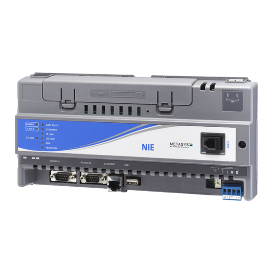
Figure 1
shows the components of the NIE.
Installation
Follow these guidelines when installing the NIE:
•
Transport the NIE in the original container to minimize vibration and shock damage to the NIE.
•
Verify that all the parts shipped with the NIE.
•
Do not drop the NIE or subject it to physical shock.
•
Do not open the NIE housing (except the data protection battery compartment). The NIE has no user-serviceable
parts inside.
Parts Included
•
one NIE with removable terminal plugs
•
one data protection battery (installed and connected when the NIE is shipped)
•
one Installation Instructions sheet
Materials and Special Tools Needed
•
three M4 (#8) fasteners appropriate for the mounting surface
•
one 20 cm (8 in.) or longer piece of DIN rail and appropriate hardware for mounting the DIN rail
NIE39/NIE49 Installation Instructions
Refer to the
W
® network, N2 Bus protocol, Modbus®, Meter-Bus (M-Bus,
ON
ORKS
Table 10
(barcode for factory use only)
Part No. 24-10050-103, Rev. H
Software Release 9.0
Issued August 2017
QuickLIT website
for the most up-to-date version of this document.
for a list of all supported dual trunk
1
Advertisement
Table of Contents

Related Manuals for Johnson Controls NIE39


Summary of Contents for Johnson Controls NIE39
- Page 1 For details, refer to the NIEx9 Driver Manager Application Note (LIT-12011919). This document describes how to install an NIE39 or NIE49, which is referred to collectively as NIE, unless specified otherwise.
-
Page 2: Location Considerations
Do not mount the NIE on surfaces prone to vibration or in areas where electromagnetic emissions can interfere with NIE communication. • Do not obstruct the NIE housing ventilation holes. • Do not mount power transformers below the NIE. NIE39/NIE49 Installation Instructions... - Page 3 1. Securely mount a 20 cm (8 in.) or longer section of DIN rail horizontally and centered in the space. 2. Ensure that the bottom two mounting clips are pulled outward and snapped firmly into the extended position (Figure NIE39/NIE49 Installation Instructions...
-
Page 4: Power Supply
Figure 1 for the location of NIE ports, modular jacks, and terminal blocks. Depending on the model, an NIE39/NIE49 supports either an MS/TP field bus trunk, an N2 Bus trunk, or a L ORKS network trunk. All models support two vendor integrations, such as two Modbus, two M-Bus, or one of each. Or if a KNX integration is required, three KNX IP Gateways are supported for one NIE39/NIE49. -
Page 5: Serial Ports
The Ethernet port, labeled ETHERNET, is an 8-pin RJ-45 network port (Figure 1) for connecting the NIE to Ethernet networks. NIE39/49 engines can connect to Ethernet networks at 10 or 100 Mbps. Use this port for connecting a Modbus TCP, M-Bus TCP, or KNX network. Wiring the NIE Important: Do not connect 24 VAC supply power to the NIE before finishing wiring and checking all wiring connections. - Page 6 Network Terminal Block and Wiring Connections ORKS 4. For Modbus RTU Protocol using the RS232C A or RS232C B serial port, use a cable to connect the RS-232/RS-485 converter to the RS232C A or RS232C B serial port on the NIE. NIE39/NIE49 Installation Instructions...
- Page 7 See Wiring Rules and Guidelines for Network Integrations for the Modbus protocol. Figure 7: Daisy Chained Devices The completed wiring should look similar to Figure NIE39/NIE49 Installation Instructions...
- Page 8 (Figure Figure 9: 24 VAC Supply Power Wiring Note: Power supply wire colors may be different on transformers not manufactured by Johnson Controls. Follow the transformer manufacturer’s instructions and the project installation drawings. 8. Connect the 24 VAC supply power wires from the transformer to the converter. No additional external power adapter is required.
- Page 9 NIE (Figure Note: Power supply wire colors may be different on transformers not manufactured by Johnson Controls. Follow the transformer manufacturer’s instructions and the project installation drawings. 5. Connect the 24 VAC supply power wires from the transformer to the -/~ and +/~ terminals as shown in...
- Page 10 MS-NIE391x-x models support up to 50 MS/TP devices total on the FC Bus with no more than two repeaters between an NIE39 and any device and a maximum of 50 devices between repeaters. Bus Length 1,500 m (5,000 ft) cable per bus segment without a repeater...
- Page 11 MS-NIE391x-x models support up to 50 Modbus RTU devices total on the FC Bus with no more than two repeaters between an NIE39 and any device and a maximum of 50 devices between repeaters. Bus Length 1,500 m (5,000 ft) cable per bus segment without a repeater...
- Page 12 Table 4: Rules for M-Bus Protocol Category Rules and Estimated Maximums General Two M-Bus integrations supported per NIEx9. See Table No restrictions in topology, but bus topology is strongly recommended. Number of Devices Depends on level converter, supported maximum is 250 devices. NIE39/NIE49 Installation Instructions...
- Page 13 Copper, solid and stranded wires with outer sheath, one- or two-twisted pair; 0.8 to 1.0 mm (20 to 18 AWG) Screen is required and must cover the entire diameter. Drain wire: Diameter minimum 0.4 mm (26 AWG) NIE39/NIE49 Installation Instructions...
- Page 14 Network trunk do not have an internal network terminator. ORKS Table 9: NIE Ethernet Network Rules Category Rules/Maximums Allowed General Point-to-point star topology with network hubs/switches Number of Devices Maximum of 100 supervisory devices may be connected to one site in the Metasys system. NIE39/NIE49 Installation Instructions...
-
Page 15: Setup And Adjustments
100 m (330 ft) CAT5 cable Terminations For 10/100 BaseT, no line terminators allowed Refer to the N1 Ethernet/IP Network Technical Bulletin (LIT-6360175) for recommended parts and part numbers. Table 10: NIE39/NIE49 Dual Trunk Options Trunk Supported Dual Trunk Applications Type... -
Page 16: Troubleshooting
Figure 13: EOL Switch Setting N2 or MS/TP Troubleshooting LED Status Indicators The NIE models have up to 11 LEDs (depending on the model) to indicate power and network communication status. Figure 14 shows the LEDs and Table 11 describes the LED indications. NIE39/NIE49 Installation Instructions... - Page 17 Site Director. For a Site Director NIE, flashes are more frequent and indicate heartbeat communications from all other NIE devices on the site. For a single NIE on a network without an Application and Data Server (ADS), there is no flicker. NIE39/NIE49 Installation Instructions...
-
Page 18: Repair Information
Description Product Code Number MS-NIE39xx-x (Base Features of Each NIE39 Series model requires a 24 VAC power supply. Each model includes two Each NIE39) RS-232-C serial ports, one USB serial port, one RS-485 or LON port, one Ethernet port, and an MS-BAT1020-0 Data Protection Battery. Up to two ports can be defined for third-party integration. - Page 19 12 V, 1.2 Ah, with a typical life of 3 to 5 years at 21°C (70°F) MS-BAT1020-0 Replacement data protection battery for NAE35, NIE39, NAE45, NIE45, NIE49, NCE25, or NIE29. Rechargeable NiMH 3.6 VDC, 500 mAh battery with a typical life of 5 to 7 years at 21°C (70°F).
-
Page 20: Technical Specifications
VGE Tool Software Software Training (Europe and Asia) The VGE tool is required to generate custom Modbus mapping tables for the NIE. Technical Specifications Table 19: NIE39 and NIE49 Power Requirement Dedicated nominal 24 VAC, Class 2 power supply (North America), SELV power supply... -
Page 21: North American Emissions Compliance
The performance specifications are nominal and conform to acceptable industry standard. For application at conditions beyond these specifications, consult the local Johnson Controls office. Johnson Controls shall not be liable for damages resulting from misapplication or misuse of its products.