Table of Contents
Advertisement
Quick Links
Application
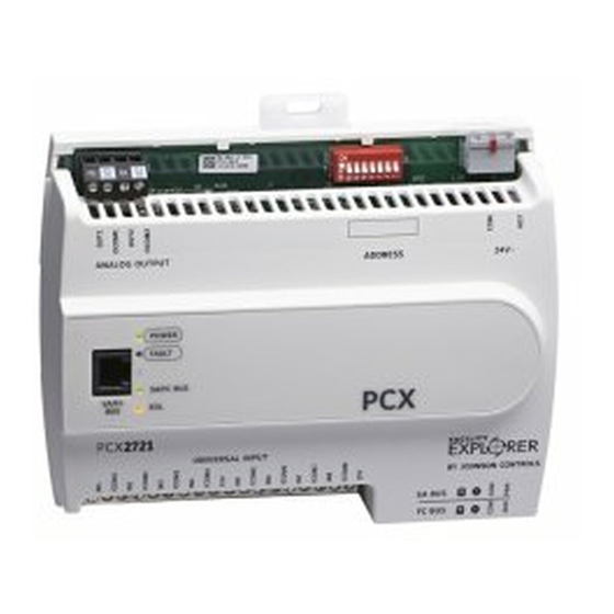
The FX-PCX2721 expansion module is part of the Facility Explorer
Controller family. FX-PCXs expand the number of Input/Output points connected to either an FX-
PCA, FX-PCG, or FX-PCV programmable controller or to a supervisory controller to monitor and
control a wide variety of HVAC equipment.
FX-PCXs operate on an RS-485 BACnet
third-party BACnet systems. FX-PCXs communicate using the BACnet MS/TP protocol when directly
connected to the FC Bus.
Note: With Release 10.1 or later of the Controller Configuration Tool (CCT), PCAs, PCGs, or
PCVs can be configured to communicate using either the BACnet MS/TP or the N2 field bus
networking protocol. The operation of the FX-PCX is not affected by the selection of the
BACnet MS/TP or the N2 protocol in the host controller, when the PCX is connected to the host
controller using the SA bus.
North American Emissions Compliance
United States
This equipment has been tested and found to comply with the limits for a Class A digital device
pursuant to Part 15 of the FCC Rules. These limits are designed to provide reasonable protection
against harmful interference when this equipment is operated in a commercial environment.
This equipment generates, uses, and can radiate radio frequency energy and, if not installed
and used in accordance with the instruction manual, may cause harmful interference to
radio communications. Operation of this equipment in a residential area may cause harmful
interference, in which case the users will be required to correct the interference at their own
expense.
Canada
This Class (A) digital apparatus meets all the requirements of the Canadian Interference-Causing
Equipment Regulations.
Cet appareil numérique de la Classe (A) respecte toutes les exigences du Règlement sur le
matériel brouilleur du Canada.
Part No. 24-10144-173 Rev. G
2019-03-22
FX-PCX2721 Expansion Input/Output
Module Installation Instructions
MS/TP Bus and integrate into Johnson Controls
®
FX-PC Series Programmable
®
®
*2410144173G*
(barcode for factory use only)
and
FX-PCX2721-0
Advertisement
Table of Contents

Related Manuals for Johnson Controls FX-PCX2721


Summary of Contents for Johnson Controls FX-PCX2721
- Page 1 FX-PCX2721 Expansion Input/Output Module Installation Instructions Application The FX-PCX2721 expansion module is part of the Facility Explorer FX-PC Series Programmable ® Controller family. FX-PCXs expand the number of Input/Output points connected to either an FX- PCA, FX-PCG, or FX-PCV programmable controller or to a supervisory controller to monitor and control a wide variety of HVAC equipment.
-
Page 2: Installation
• Three fasteners appropriate for the mounting surface (M4 screws or #8 screws) • One 20 cm (8 in.) or longer piece of 35 mm DIN rail and appropriate hardware for DIN rail mount • Small straight-blade screwdriver for securing wires in the terminal blocks FX-PCX2721 Expansion Input/Output Module Installation Instructions... - Page 3 DIN rail mount applications Mounting the FX-PCX expansion module horizontally on 35 mm DIN rail is the preferred method. To mount an expansion module on a 35 mm DIN rail, complete the following steps: FX-PCX2721 Expansion Input/Output Module Installation Instructions...
-
Page 4: Wall Mount Applications
See the following figure for mounting dimensions listed in millimeters and inches. Inches are listed in parenthesis. The following figure also illustrates the DIN rail channel and the mounting clips in an extended position. FX-PCX2721 Expansion Input/Output Module Installation Instructions... - Page 5 Figure 2: Back of expansion module FX-PCX2721 Expansion Input/Output Module Installation Instructions...
- Page 6 FX-PCX2721 physical features The following figure displays the physical features of the FX-PCX2721, and the accompanying table provides a description of the physical features and a reference to further information where required. Figure 3: FX-PCX2721 physical features Table 1: FX-PCX2721 physical features callouts and descriptions...
- Page 7 Important: Use copper conductors only. Make all wiring in accordance with local, national, and regional regulations. Important: Electrostatic discharge can damage expansion module components. Use proper electrostatic discharge precautions during installation, setup, and servicing to avoid damaging the expansion module. FX-PCX2721 Expansion Input/Output Module Installation Instructions...
- Page 8 When connecting the FX-PCX to an SA bus, wire the bus terminal block plugs on the expansion module and other SA bus devices in a daisy-chain configuration using 4-wire twisted, shielded cable as shown in Figure 5. FX-PCX2721 Expansion Input/Output Module Installation Instructions...
- Page 9 Wire the 24 VAC supply power wires from the transformer to the HOT and COM terminals on the terminal plug as shown in Figure 7. The middle terminal on the supply power terminal block is not used. FX-PCX2721 Expansion Input/Output Module Installation Instructions...
- Page 10 Field Bus system, refer to the WNC1800/FX-ZFR182x Pro Series Wireless Field Bus System Bulletin (LIT-12012378). Termination details A set of Johnson Controls termination diagrams provides details for wiring inputs and outputs to the controllers. See the figures in this section for the applicable termination diagrams. FX-PCX2721 Expansion Input/Output Module Installation Instructions...
- Page 11 Type of Termination diagrams device Input/ Output Temperature Sensor Voltage Input - External Source Voltage Input - Internal Source Voltage Input (Self-Powered) Current Input - External Source (Isolated) Current Input - Internal Source (2-wire) FX-PCX2721 Expansion Input/Output Module Installation Instructions...
- Page 12 Type of Termination diagrams device Input/ Output Current Input - Internal Source (3-wire) Current Input - External Source (in Loop) Feedback from EPP-1000 Dry Contact (Binary Input) 0–10 VDC Output to Actuator (External Source) FX-PCX2721 Expansion Input/Output Module Installation Instructions...
- Page 13 Table 2: Termination details Type of field Type of Termination diagrams device Input/ Output 0–10 VDC Output to Actuator (Internal Source) Analog Output (Current) 4–20 mA Output to Actuator Voltage (Analog Output) 4–20 mA Output to Actuator FX-PCX2721 Expansion Input/Output Module Installation Instructions...
- Page 14 Internal 100 ohm load impedance Note: A current loop fail-safe jumper can be positioned to maintain a closed 4 to 20 mA current loop, even when the power to the expansion module is interrupted or off. FX-PCX2721 Expansion Input/Output Module Installation Instructions...
- Page 15 Table 4. Internal 12 V. 15k ohm pull up Qualified Sensors: 0-2k ohm potentiometer, RTD (1k Nickel [ Johnson Controls sensor], 1k Platinum, and A99B Silicon Temperature Sensor) Negative Temperature Coefficient (NTC) Sensor (10k Type L, 10k JCI Type II, 2.252k Type II)
- Page 16 Use the following figure to estimate the maximum cable length relative to the wire size and the load current (in mA) when wiring inputs and outputs. Note: The following information applies to low-voltage (<30 V) inputs and outputs only. FX-PCX2721 Expansion Input/Output Module Installation Instructions...
- Page 17 Port label labels Requirements FC BUS FC or SA Bus Communications FC Bus: 0.6 mm (22 AWG) stranded, 3-wire twisted, shielded cable recommended. Signal Reference (Common) for FC SA BUS or SA Bus communications FX-PCX2721 Expansion Input/Output Module Installation Instructions...
- Page 18 38,400 baud. For more information, refer to the following documents depending on your system (FX or BCPro): FX-PC Series Controllers MS/TP Communications Bus Technical Bulletin (LIT-12011670) or MS/TP Communications Bus for BCPro Technical Bulletin (LIT-12011908). FX-PCX2721 Expansion Input/Output Module Installation Instructions...
-
Page 19: Setup And Adjustments
DIP switch block at the top of the expansion module. Device addresses 4 through 127 are the valid addresses for these expansion modules. The following table describes the FC bus and SA bus device addresses for Johnson Controls MS/TP communications bus applications:... - Page 20 SA or FC bus. When a controller with switch 128 ON and a device address from 4 to 127 is connected to a wired field bus, the entire field bus is rendered inoperable until the controller is disconnected or switch 128 is set to Off. FX-PCX2721 Expansion Input/Output Module Installation Instructions...
- Page 21 See Figure 11 for the EOL switch location. The default EOL switch position is OFF. Figure 11: End-of-Line switch positions To set the EOL switch on an expansion module, complete the following steps: FX-PCX2721 Expansion Input/Output Module Installation Instructions...
- Page 22 4 to 20 mA analog inputs. Current loop jumper IDs The following table identifies the current loop jumpers associated with each UI on the FX-PCX2721 expansion module. Table 8: FX-PCX2721 UI Inputs and jumper labels...
- Page 23 Table 8: FX-PCX2721 UI Inputs and jumper labels Universal Input label Jumper label on circuit board Commissioning You commission controllers with Controller Configuration Tool (CCT) software, either via a Bluetooth Wireless Commissioning Converter, a ZigBee® wireless dongle, or in BACnet Router mode when connected to Supervisory Controller.
-
Page 24: Troubleshooting
Repair information If an expansion module fails to operate within its specifications, replace the expansion module. For a replacement expansion module, contact your Johnson Controls representative. Accessories See the following table for expansion module accessories ordering information. Table 10: Accessories ordering information... -
Page 25: Technical Specifications
Storage: -40°C to 80°C (-40°F to 176°F); 5% to 95% RH noncondensing Addressing DIP switch set; valid expansion module device addresses 4–127 (Device addresses 0–3 and 128–255 are reserved and not valid expansion module addresses) FX-PCX2721 Expansion Input/Output Module Installation Instructions... - Page 26 Canada: UL Listed, File E107041, CCN PAZX7 CAN/CSA C22.2 No.205, Signal Equipment Industry Canada Compliant, ICES-003 Europe: Johnson Controls declares that this product is in compliance with the essential requirements and other relevant provisions of the EMC Directive. Australia and New Zealand: RCM Mark, Australia/NZ Emissions...
-
Page 27: Points Of Single Contact
NO. 32 CHANGJIJANG RD NEW DISTRICT 45143 ESSEN MILWAUKEE WI 53202 WUXI JIANGSU PROVINCE 214028 GERMANY CHINA © 2019 Johnson Controls. All rights reserved. All specifications and other information shown were current as of document revision and are subject to change without notice. www.johnsoncontrols.com...