Table of Contents
Advertisement
Quick Links
Advertisement
Table of Contents

Related Manuals for Asus M5A78L-M LE/USB3


Summary of Contents for Asus M5A78L-M LE/USB3
- Page 1 M5A78L-M LE/USB3...
- Page 2 INCIDENTAL, OR CONSEQUENTIAL DAMAGES (INCLUDING DAMAGES FOR LOSS OF PROFITS, LOSS OF BUSINESS, LOSS OF USE OR DATA, INTERRUPTION OF BUSINESS AND THE LIKE), EVEN IF ASUS HAS BEEN ADVISED OF THE POSSIBILITY OF SUCH DAMAGES ARISING FROM ANY DEFECT OR ERROR IN THIS MANUAL OR PRODUCT.
-
Page 3: Table Of Contents
BIOS information Managing and updating your BIOS ............. 2-1 2.1.1 ASUS Update utility ................ 2-1 2.1.2 ASUS EZ Flash 2 utility ..............2-2 2.1.3 ASUS CrashFree BIOS 3 ..............2-3 BIOS setup program ..................2-4 2.2.1 BIOS menu screen ................2-5 2.2.2... - Page 4 2.5.6 Anti Surge Support [Enabled] ............2-18 Boot menu ....................2-19 2.6.1 Boot Device Priority ..............2-19 ............2-19 2.6.3 Security ..................2-20 Tools menu ....................2-22 2.7.1 ASUS EZ Flash 2 ................2-22 ................. 2-22 Exit menu ....................2-23...
-
Page 5: Safety Information
Safety information Electrical safety before relocating the system. When adding or removing devices to or from the system, ensure that the power cables for the devices are unplugged before the signal cables are connected. If possible, disconnect all power cables from the existing system before you add a device. Before connecting or removing signal cables from the motherboard, ensure that all power cables are unplugged. - Page 6 Refer to the following sources for additional information and for product and software updates. ASUS websites The ASUS website provides updated information on ASUS hardware and software products. Refer to the ASUS contact information. Optional documentation that may have been added by your dealer. These documents are not part of the standard package.
-
Page 7: Package Contents
Socket AM3+ for AMD FX™ / Phenom™ II / Athlon™ II / Sempron™ 100 series processors ® Cool ‘n’ Quiet™ Technology Supports CPU up to 125W * Refer to www.asus.com for the AMD ® CPU support list ® Chipset 760G(780L) / SB710 Up to 5.2GT/s HyperTransport™... - Page 8 ASUS EPU Features - EPU Core Unlocker ASUS Exclusive Features - Anti-Surge - ASUS All 5K-Hour Solid Capacitors - RAM Overcurrent Protection - ESD Guards - Stainless Steel Back I/O ASUS Quiet Thermal Solution - ASUS Fan Xpert ASUS EZ DIY...
-
Page 9: Chapter 1: Product Introduction
Take note of the following precautions before you install motherboard components or change any motherboard settings. to static electricity. bag that came with the component. switched off or the power cord is detached from the power supply. Failure to do so ASUS M5A78L-M LE/USB3... -
Page 10: Motherboard Overview
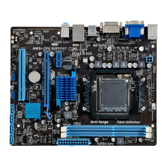
1.2.2 Screw holes Place six screws into the holes indicated by circles to secure the motherboard to the chassis. Place this side towards the rear of the chassis M5A78L-M LE/USB3 Chapter 1: Product introduction... - Page 11 1.2.3 Motherboard layout 19.8cm(7.8in) KBMS_USB34 CPU_FAN ATX12V USB3_E12 1042A CHA_FAN LAN_USB12 ® AUDIO 760G PCIEX1_1 Realtek 8111GR PCIEX16 16Mb M5A78L-M LE/USB3 BIOS Super ® SB710 PCI1 887-VD2 USB78 USB56 SATA3G_1 SATA3G_2 SATA3G_3 SATA3G_4 CLRTC AAFP ASUS M5A78L-M LE/USB3...
-
Page 12: Central Processing Unit (Cpu)
1.2.4 Layout contents Connectors/Headers/Slots/LED Page 1-16 1-15 1-17 1-18 1-17 1-19 1-12 1-19 Central Processing Unit (CPU) ® M5A78L-M LE/USB3 M5A78L-M LE/USB3 CPU socket AM3+ Chapter 1: Product introduction... -
Page 13: Cpu Installation
1.3.1 CPU installation ASUS M5A78L-M LE/USB3... -
Page 14: Cpu Heatsink And Fan Assembly Installation
1.3.2 CPU heatsink and fan assembly installation before you install the heatsink and fan if necessary. To install the CPU heatsink and fan assembly Chapter 1: Product introduction... - Page 15 To uninstall the CPU heatsink and fan assembly ASUS M5A78L-M LE/USB3...
-
Page 16: System Memory
System memory 1.4.1 Overview better performance with less power consumption. Channel Sockets M5A78L-M LE/USB3 M5A78L-M LE/USB3 240-pin DDR3 DIMM sockets sockets. operation. ® following: ® ® motherboard. ® support site at Chapter 1: Product introduction... -
Page 17: Installing A Dimm
2.4 Advanced menu for manual memory www.asus.com 1.4.3 Installing a DIMM ASUS M5A78L-M LE/USB3... -
Page 18: Expansion Slots
To remove a DIMM Expansion slots the slots and the expansion cards that they support. cause you physical injury and damage motherboard components. 1.5.1 Installing an expansion card To install an expansion card: make the necessary hardware settings for the card. use. - Page 19 – – – – – – – – – – shared – shared – – – – – – – – – shared – – – – – – – – shared – – – – ASUS M5A78L-M LE/USB3 1-11...
-
Page 20: Headers
Headers Clear RTC RAM (2-pin CLRTC) CLRTC M5A78L-M LE/USB3 PIN 1 M5A78L-M LE/USB3 Clear RTC RAM To erase the RTC RAM: enter data. battery. 1-12 Chapter 1: Product introduction... -
Page 21: Connectors
LAN port LED indications ACT/LINK SPEED Activity/Link LED Speed LED Status Description Status Description LAN port Line In port (light blue). audio sources. Line Out port (lime). Microphone port (pink). This port connects to a microphone. ASUS M5A78L-M LE/USB3 1-13... - Page 22 Headset Port 4.1-channel 5.1-channel 7.1-channel 2.1-channel — — — output. USB 2.0 ports 1 and 2. USB 3.0 ports 1 and 2. ® operating system’s setting. DVI-D port. Serial port (COM). USB 2.0 ports 3 and 4. 1-14 Chapter 1: Product introduction...
-
Page 23: Internal Connectors
CPU and chassis fan connectors (4-pin CPU_FAN, 3-pin CHA_FAN) black wire of each cable matches the ground pin of the connector. CPU_FAN CHA_FAN +12V M5A78L-M LE/USB3 FANIN M5A78L-M LE/USB3 Fan connectors place jumper caps on the fan connectors. ASUS M5A78L-M LE/USB3 1-15... - Page 24 Power OK -5 Volts PIN 1 +5 Volts +5 Volts PSON# M5A78L-M LE/USB3 +3 Volts -12 Volts +3 Volts +3 Volts PIN 1 M5A78L-M LE/USB3 ATX power connectors power plugs. not boot up. for details. 1-16 Chapter 1: Product introduction...
- Page 25 Serial ATA 3.0 Gb/s connectors (7-pin SATA3G 1~4) controller. SATA3G_1 SATA3G_2 SATA3G_3 SATA3G_4 M5A78L-M LE/USB3 M5A78L-M LE/USB3 SATA 3.0Gb/s connectors [RAID] for details. ® ® [AHCI] for details. Speaker connector (4-pin SPEAKER) This 4-pin connector is for the chassis-mounted system warning speaker. The speaker allows you to hear system beeps and warnings.
- Page 26 PIN 1 M5A78L-M LE/USB3 +HDD_LED RESET M5A78L-M LE/USB3 System panel connector ATX power button/soft-off button (2-pin PWR_BTN) This 2-pin connector is for the system power button. Reset button (2-pin RESET) This 2-pin connector is for the chassis-mounted reset button for system reboot without turning off the system power.
- Page 27 AAFP PIN 1 PIN 1 M5A78L-M LE/USB3 HD-audio-compliant Legacy AC’97 pin definition compliant definition M5A78L-M LE/USB3 Front panel audio connector the Azalia Front Panel [HD] 2.4.4 Onboard Devices for details. USB 2.0 connectors (10-1 pin USB56, USB78) USB78 USB56 PIN 1...
-
Page 28: Software Support
® the features of your hardware. detailed information. ® 1.8.2 Support DVD information www.asus.com for updates. To run the Support DVD The following screen is for reference only. Click an icon to display Support DVD/motherboard information Click an item to install... -
Page 29: Chapter 2: Bios Information
To install ASUS Update: Specials Utilities AI Suite II ® Updating the BIOS To update the BIOS: ® Start > Programs > ASUS > AI Suite II > AI Suite II X.XX.XX Update ASUS Update ASUS Update ASUS M5A78L-M LE/USB3... -
Page 30: Asus Ez Flash 2 Utility
Update BIOS from the Internet Next Next Next Next Open Open 2.1.2 ASUS EZ Flash 2 utility <Alt> + <F2> Tools EZ Flash 2 and <Enter> <Tab> FAT 32/16 Chapter 2: BIOS information... -
Page 31: Asus Crashfree Bios 3
2.1.3 ASUS CrashFree BIOS 3 MA78LMU3.ROM Recovering the BIOS the Load Setup Defaults 2.8 Exit menu for ASUS M5A78L-M LE/USB3... -
Page 32: Bios Setup Program
BIOS setup program Entering BIOS Setup at startup <Delete> <Delete> Entering BIOS Setup after POST <Ctrl>+<Alt>+<Delete> power button reset button <Ctrl>+<Alt>+<Del> Load Setup Defaults Exit 2.8 Exit Menu Chapter 2: BIOS information... -
Page 33: Bios Menu Screen
2.2.1 BIOS menu screen Menu items Menu bar General help M5A78L-M LE/USB3 BIOS Setup Version 0211 Main Advanced Power Boot Tools Exit Main Settings Use [ENTER], [TAB] System Time [19:34:30] or [SHIFT-TAB] to System Date [Thu 2/20/2014] SATA3G_1 :[Not Detected]... -
Page 34: Menu Items
2.2.4 Menu items 2.2.5 Submenu items <Enter> <Enter> 2.2.7 Pop-up window M5A78L-M LE/USB3 BIOS Setup Version 0211 2.2.7 Pop-up window Main Advanced Power Boot Tools Exit Power Settings Select the ACPI state used for System Suspend Mode [Auto] Suspend. ACPI 2.0 Support [Enabled] <Enter>... -
Page 35: Main Menu
Main menu 2.2.1 BIOS menu screen M5A78L-M LE/USB3 BIOS Setup Version 0211 Main Advanced Power Boot Tools Exit Main Settings Use [ENTER], [TAB] System Time [19:34:30] or [SHIFT-TAB] to System Date [Thu 08/14/2011] SATA3G_1 :[Not Detected] Use [+] or [-] to... -
Page 36: System Information
PIO Mode [Auto] DMA Mode [Auto] SMART Monitoring [Auto] 32Bit Data Transfer [Enabled] <Enter> OnChip SATA Channel [Enabled] OnChip SATA Channel Enabled 2.3.5 System Information BIOS Information Processor System Memory Chapter 2: BIOS information... -
Page 37: Advanced Menu
Advanced menu The Advanced M5A78L-M LE/USB3 BIOS Setup Version 0211 Main Advanced Power Boot Tools Exit Advanced Settings Adjust System Frequency/Voltage etc. Chipset PCIPnP Select Screen Select Item Change Field Select Field General Help Save and Exit Exit v02.61 (C)Copyright 1985-2015, American Megatrends, Inc. - Page 38 PCIE Overclocking [Auto] PCIE Overclocking to [Manual] CPU Ratio [Auto] CPU/NB Frequency [Auto] CPU Over Voltage [Auto] VDDNB Over Voltage [Auto] LoadLine Calibration [Auto] HT Link Speed [Auto] to [Manual] Chapter 2: BIOS information...
- Page 39 Memory Voltage [Auto] PCI/PCIe CLK Status [Enabled] ASUS M5A78L-M LE/USB3 2-11...
- Page 40 GART Error Reporting [Disabled] Microcode Updation [Enabled] Secure Virtual Machine Mode [Disabled] Cool ‘n’ Quiet [Enabled] ® C1E Support [Disabled] Advanced Clock Calibration [Disabled] [Auto] [All Cores] [Per Core] Advanced Clock Calibration to [Auto] [All Cores] [Per Core] 2nd / 3rd / 4th Core [On] Active CPU Cores to [Manual] Value (All Cores) [-2%] Advanced Clock Calibration to [All Cores]...
-
Page 41: Chipset
Value (Core 0) / (Core 1) / (Core 2) / (Core 3) [-2%] Advanced Clock Calibration to [Per Core] 2.4.3 Chipset ECC Mode Internal Graphics Primary Video Controller [GFX0-GPP-IGFX-PCI] ASUS M5A78L-M LE/USB3 2-13... - Page 42 [512MB] [1GB] Surround View [Auto] Frame Buffer Location [Above 4G] Serial Port1 Address [3F8/IRQ4] HDAudio Controller [Enabled] OnBoard LAN Controller [Enabled] USB 3.0 Controller [Enabled] 2-14 Chapter 2: BIOS information...
-
Page 43: Pcipnp
2.4.5 PCIPnP Plug and Play O/S [No] [No] [Yes] <Enter> The Module Version and USB Devices Enabled None USB Functions [Enabled] USB Functions to [Enabled] USB 2.0 Controller [Enabled] Legacy USB Support [Auto] ASUS M5A78L-M LE/USB3 2-15... -
Page 44: Power Menu
Power menu <Enter> M5A78L-M LE/USB3 BIOS Setup Version 0211 Main Advanced Power Boot Tools Exit Select the ACPI state Power Settings used for System Suspend. Suspend Mode [Auto] ACPI 2.0 Support [Enabled] ACPI APIC Support [Enabled] Anti Surge Support [Enabled]... - Page 45 CPU / Chassis Fan Speed [N/A], [xxxxRPM], or [Ignored] [gnored] VCORE Voltage, 3.3V Voltage, 5V Voltage, 12V Voltage [xx.xxxV] or [Ignored] CPU Q-Fan Function [Enabled] CPU Q-Fan Function to [Enabled] CPU Q-Fan Mode CPU Upper Temperature [70 C/158 ASUS M5A78L-M LE/USB3 2-17...
-
Page 46: Anti Surge Support [Enabled]
CPU Fan Max. Duty Cycle(%) [100%] CPU Lower Temperature [20 C/68 CPU Fan Min. Duty Cycle(%) [20%] 2.5.6 Anti Surge Support [Enabled] 2-18 Chapter 2: BIOS information... -
Page 47: Boot Menu
Boot menu The Boot <Enter> M5A78L-M LE/USB3 BIOS Setup Version 0211 Main Advanced Power Boot Tools Exit Boot Settings Device Priority sequence. Boot Device Priority drive (Floppy Drive B:) may appear when you set Security the CD-ROM drive as the... -
Page 48: Security
AddOn ROM Display Mode [Force BIOS] Bootup Num-Lock [On] Wait for ‘F1’ If Error [Enabled] [Enabled] 2.6.3 Security <Enter> Change Supervisor Password Supervisor Password item Not Installed Installed Change Supervisor Password <Enter> <Enter> Password Installed Change Supervisor Password <Enter> Password uninstalled 1.6 Headers Chapter 2: BIOS information... - Page 49 User Access Level [Full Access] No Access View Only Limited Full Access Change User Password User Password item on top of the Not Installed Installed Change User Password <Enter> <Enter> Password Installed Clear User Password Password Check [Setup] [Setup] [Always] ASUS M5A78L-M LE/USB3 2-21...
-
Page 50: Tools Menu
Tools menu The Tools <Enter> M5A78L-M LE/USB3 BIOS Setup Version 0211 Main Advanced Power Boot Tools Exit Tools Settings Press ENTER to run the utility to select ASUS EZ Flash 2 and update BIOS. This utility supports: 1.FAT 12/16/32 (r/w) 2.NTFS (read only) -
Page 51: Exit Menu
Exit menu The Exit M5A78L-M LE/USB3 BIOS Setup Version 0211 Main Advanced Power Boot Tools Exit Exit Options Exit system setup after saving the cahnges. Exit & Save Changes Exit & Discard Changes Discard Changes for this operation. Load Setup Defaults <Esc>... - Page 52 2-24 Chapter 2: BIOS information...
- Page 53 Consult the dealer or an experienced radio/TV technician for help. The use of shielded cables for connection of the monitor to the graphics card is required expressly approved by the party responsible for compliance could void the user’s authority to operate this equipment. ASUS M5A78L-M LE/USB3...
- Page 54 IC: Canadian Compliance Statement 210 of Industry Canada. This Class B device meets all the requirements of the Canadian interference-causing equipment regulations. This device complies with Industry Canada license exempt RSS standard(s). Operation is subject to the following two conditions: (1) this device may not cause interference, and (2) this device must accept any interference, including interference that may cause undesired operation of the device.
- Page 55 ASUS Recycling/Takeback Services ASUS recycling and takeback programs come from our commitment to the highest standards for protecting our environment. We believe in providing solutions for you to be able to responsibly recycle our products, batteries, other components as well as the packaging materials.
- Page 56 Português A AsusTek Inc. declara que este dispositivo está em English AsusTek Inc. hereby declares that this device is in compliance with conformidade com os requisitos essenciais e outras disposições relevantes the essential requirements and other relevant provisions of CE Directives. das Diretivas da CE.
- Page 57 +1-510-739-3777 +1-510-608-4555 Web site http://www.asus.com/us/ Technical Support Support fax +1-812-284-0883 Telephone +1-812-282-2787 Online support http://www.service.asus.com/ ASUS COMPUTER GmbH (Germany and Austria) Address Harkort Str. 21-23, D-40880 Ratingen, Germany +49-2102-959911 Web site http://www.asus.com/de Online contact http://eu-rma.asus.com/sales Technical Support Telephone +49-1805-010923* Support Fax...
- Page 58 Appendices...