Table of Contents
Advertisement
Advertisement
Table of Contents

Related Manuals for Asus M5A97 R2.0


Summary of Contents for Asus M5A97 R2.0
- Page 1 M5A97 R2.0...
- Page 2 Product warranty or service will not be extended if: (1) the product is repaired, modified or altered, unless such repair, modification of alteration is authorized in writing by ASUS; or (2) the serial number of the product is defaced or missing.
-
Page 3: Table Of Contents
DIP (Dual Intelligent Processors) - TPU (TurboV Processing Unit) & EPU (Energy Processing Unit) ........1-2 1.1.3 ASUS Exclusive Features ............1-2 1.1.4 ASUS Quiet Thermal Solution ............. 1-3 1.1.5 ASUS EZ DIY ................1-3 1.1.6 Other Features ................1-4 Motherboard overview ................ - Page 4 Network Stack ................3-20 Monitor menu ................... 3-21 Boot menu ....................3-24 Tools menu ....................3-26 3.8.1 ASUS EZ Flash 2 Utility ............3-26 3.8.2 ASUS SPD Information ............. 3-26 3.8.3 ASUS O.C. Profile ..............3-26 Exit menu ....................3-27 3.10...
- Page 5 Requirements ................6-1 6.1.2 Before you begin ................. 6-1 6.1.3 Installing two CrossFireX™ graphics cards ........ 6-2 6.1.4 Installing the device drivers ............6-3 6.1.5 Enabling the AMD CrossFireX™ technology ......6-3 ® Appendices Notices ........................A-1 ASUS contact information ..................A-4...
-
Page 6: Safety Information
Safety information Electrical safety • To prevent electrical shock hazard, disconnect the power cable from the electrical outlet before relocating the system. • When adding or removing devices to or from the system, ensure that the power cables for the devices are unplugged before the signal cables are connected. If possible, disconnect all power cables from the existing system before you add a device. -
Page 7: About This Guide
Refer to the following sources for additional information and for product and software updates. ASUS websites The ASUS website provides updated information on ASUS hardware and software products. Refer to the ASUS contact information. Optional documentation Your product package may include optional documentation, such as warranty flyers, that may have been added by your dealer. -
Page 8: Conventions Used In This Guide
Conventions used in this guide To ensure that you perform certain tasks properly, take note of the following symbols used throughout this manual. DANGER/WARNING: Information to prevent injury to yourself when trying to complete a task. CAUTION: Information to prevent damage to the components when trying to complete a task IMPORTANT: Instructions that you MUST follow to complete a task. -
Page 9: M5A97 R2.0 Specifications Summary
ECC, Non-ECC, unbuffered memory • The maximum 32GB memory capacity can be supported with 8GB or above DIMMs. ASUS will update the memory QVL once the DIMMs are available in the market. • Due to CPU spec, AMD 100 Series CPUs support up to DDR3 1066MHz. With ASUS design, this motherboard can support up to DDR3 1333MHz. - Page 10 - Auto Tuning, TurboV ASUS Power Design - 4+2 Phase Power Design ASUS Exclusive Features - ASUS UEFI BIOS EZ Mode featuring friendly graphics user interface - ASUS Remote GO! - ASUS USB 3.0 Boost - ASUS Network iControl - Front Panel USB 3.0 Support...
- Page 11 1 x 8-pin EATX 12V power connector BIOS 64Mb Flash ROM, UEFI BIOS, PnP, DMI 2.0, WfM 2.0, SM BIOS V2.7, ACPI 2.0a Multi-language BIOS, ASUS EZ Flash 2, F12 PrintScreen, F3 Shortcut Function and ASUS DRAM SPD (Serieal Presence Detect) memory information Manageability WfM 2.0, DMI 2.0, WOL by PME, WOR by PME, PXE...
-
Page 12: Package Contents
ASUS M5A97 R2.0 motherboard User Guide Support DVD 2 x Serial ATA 6.0 Gb/s cables 1 x ASUS I/O Shield • If any of the above items is damaged or missing, contact your retailer. • The illustrated items above are for reference only. Actual product specifications may... -
Page 13: Installation Tools And Components
Installation tools and components 1 bag of screws Philips (cross) screwdriver PC chassis Power supply unit AMD AM3+ CPU AMD AM3+ compatible CPU Fan DIMM SATA hard disk drive SATA optical disc drive (optional) Graphics card (optional) The tools and components in the table above are not included in the motherboard package. xiii... -
Page 15: Product Introduction
USB 2.0. Front Panel USB 3.0 Support ASUS provides standardized USB 3.0 front panel support which is compatible with any chassis. Enjoy faster throughput of USB 3.0 without relegating cables or hard-to-reach rear I/O. -
Page 16: Dip (Dual Intelligent Processors) - Tpu (Turbov Processing Unit) & Epu (Energy Processing Unit)
Ai Charger+ ASUS Ai Charger+, the latest Ai Charger* version, brings you to a new level of USB3.0 fast charging experience. With its easy and user-friendly interface, you can easily charge iPod, iPhone, iPad, but also BC 1.1** standard mobile devices three times*** as fast as before. -
Page 17: Asus Quiet Thermal Solution
ASUS Fan Xpert ASUS Fan Xpert intelligently allows you to adjust the CPU fan and chassis fan speeds according to different ambient temperatures caused by different climate conditions in different geographic regions and your PC’s loading. The built-in variety of useful profiles offer flexible controls of fan speed to achieve a quiet and cool environment. -
Page 18: Other Features
ASUS EZ Flash 2 ASUS EZ Flash 2 is a user-friendly utility that allows you to update the BIOS without using a bootable floppy disk or an OS-based utility. ASUS MyLogo 2™ Turn your favorite photos into 256-color boot logos to personalize your system. -
Page 19: Motherboard Overview
Motherboard overview 1.2.1 Before you proceed Take note of the following precautions before you install motherboard components or change any motherboard settings. • Unplug the power cord from the wall socket before touching any component. • Before handling components, use a grounded wrist strap or touch a safely grounded object or a metal object, such as the power supply case, to avoid damaging them due to static electricity. -
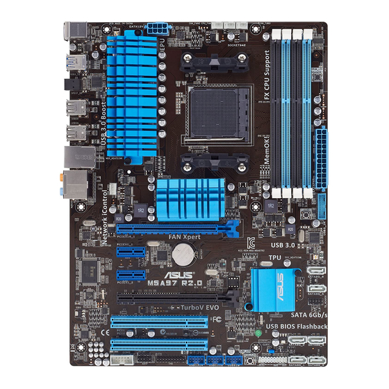
Page 20: Motherboard Layout
1.2.2 Motherboard layout 22.9cm(9.0in) KBMS CHA_FAN2 CPU_FAN CHA_FAN3 EATX12V USB3_12 DRAM_LED MemOK! 1042 SPDIF_O2 USB56 USB34 LAN1_USB12 CHA_FAN1 AUDIO ® PCIEX16_1 8111F 1042 PCIEX1_1 Lithium Cell CMOS Power 9LPRS477 SATA6G_6 Super PCIEX1_2 64Mb ® SATA6G_5 BIOS M5A97 R2.0 SB950 PCIEX16_2 PCI1 SATA6G_2 SATA6G_4 SB_PWR... -
Page 21: Layout Contents
Layout contents Connectors/Jumpers/Slots/LED Page 1. CPU and chassis fan connectors (4-pin CPU_FAN and 4-pin CHA_FAN1/2/3) 1-21 2. ATX power connectors (24-pin EATXPWR, 8-pin EATX12V) 1-22 3. AMD AM3+ CPU socket 4. DDR3 DIMM slots 5. DRAM LED (DRAM_LED) 1-20 6. MemOK! switch 1-17 7. -
Page 22: Central Processing Unit (Cpu)
1.2.3 Central Processing Unit (CPU) The motherboard comes with an AM3+/AM3 socket designed for AMD FX™ Series / ® Phenom™ II / Athlon™ II / Sempron™ 100 Series Processors. M5A97 R2.0 M5A97 R2.0 CPU socket AM3+ Ensure that all power cables are unplugged before installing the CPU. The AM3+ socket has a different pinout from the 940-pin socket designed for the AMD Opteron processor. -
Page 23: Recommended Memory Configurations
• The maximum 64GB memory capacity can be supported with 8GB or above DIMMs. ASUS will update the memory QVL once the DIMMs are available in the market. • The default memory operation frequency is dependent on its Serial Presence Detect (SPD), which is the standard way of accessing information from a memory module. - Page 24 M5A97 R2.0 Motherboard Qualified Vendors Lists (QVL) DDR3-2133 (O.C.) MHz capability DIMM socket support Chip Chip (Optional) Vendors Part No. Size Timing Voltage Brand 1 DIMM 2 DIMMs CORSAIR CMT4GX3M2A2133C9(XMP) 4GB ( 2x 2GB ) DS 9-10-9-24 1.65 • • CORSAIR CMT4GX3M2B2133C9(Ver7.1)(XMP) 4GB ( 2x 2GB ) DS 9-9-9-24...
- Page 25 DDR3-1600 MHz capability DIMM socket support Chip (Optional) Vendors Part No. Size Chip NO. Timing Voltage Brand 1 DIMM 2 DIMMs 4 DIMMs 3CCD- A-DATA AM2U16BC2P1 A-DATA • • • 1509A 3CCD- A-DATA AM2U16BC4P2 A-DATA • • 1509A A-DATA AX3U1600GC4G9(XMP) 1.55~1.75 •...
- Page 26 DDR3-1333 MHz capability DIMM socket support (Optional) Vendors Part No. Size Chip Brand Chip NO. Timing Voltage DIMM DIMMs DIMMs ACTICA ACT1GHU64B8F1333S SAMSUNG K4B1G0846F • • • ACTICA ACT1GHU72C8G1333S SAMSUNG K4B1G0846F(ECC) • • • ACTICA ACT2GHU64B8G1333M Micron D9KPT • • •...
- Page 27 4 DIMMs: Supports four (4) modules inserted into both the blue and black slots as two pairs of Dual-channel memory configuration. • When overclocking, some AMD CPU models may not support DDR3 1600 or higher frequency DIMMs. • Visit the ASUS website for the latest QVL. M5A97 R2.0 1-13...
-
Page 28: Expansion Slots
1.2.5 Expansion slots Unplug the power cord before adding or removing expansion cards. Failure to do so may cause you physical injury and damage motherboard components. M5A97 R2.0 Slot No. Slot Description PCIe 2.0 x16_1 slot [blue] (at x16 mode) PCIe 2.0 x1_1 slot PCIe 2.0 x1_2 slot PCIe 2.0 x16_2 slot [black] (at x4 mode) -
Page 29: Irq Assignments For This Motherboard
• In single VGA card mode, use the PCIe 2.0 x16_1 slot (navy blue) for a PCI Express x16 graphics card to get better performance. • We recommend that you provide sufficient power when running CrossFireX™ mode. • Connect a chassis fan to the motherboard connector labeled CHA_FAN1/2/3 when using multiple graphics cards for better thermal environment. -
Page 30: Onboard Switches And Buttons
1.2.6 Onboard switches and buttons Onboard switches and buttons allow you to fine-tune performance when working on a bare or open-case system. This is ideal for overclockers and gamers who continually change settings to enhance system performance. DirectKey button This feature allows your system to go to the BIOS Setup program with the press of a button. - Page 31 BIOS default settings. A message will appear during POST reminding you that the BIOS has been restored to its default settings. • We recommend that you download and update to the latest BIOS version from the ASUS website at www.asus.com after using the MemOK! function. M5A97 R2.0 1-17...
- Page 32 BIOS Flashback button USB BIOS Flashback allows you to easily update the BIOS without entering the BIOS or operating system. Just connect the USB storage device containing the BIOS file to the USB port, press the BIOS Flashback button, and the BIOS is updated automatically.
-
Page 33: Jumpers
1.2.7 Jumpers Clear RTC RAM (CLRTC) This jumper allows you to clear the Real Time Clock (RTC) RAM in CMOS. You can clear the CMOS memory of date, time, and system setup parameters by erasing the CMOS RTC RAM data. The onboard button cell battery powers the RAM data in CMOS, which include system setup information such as system passwords. -
Page 34: Onboard Leds
1.2.8 Onboard LEDs Standby Power LED The motherboard comes with a standby power LED that lights up to indicate that the system is ON, in sleep mode, or in soft-off mode. This is a reminder that you should shut down the system and unplug the power cable before removing or plugging in any motherboard component. -
Page 35: Cpu And Chassis Fan Connectors
• The CPU_FAN connector supports a CPU fan of maximum 1A (12 W) fan power. • Only the CPU_FAN and CHA_FAN1/2/3 connectors support the ASUS Fan Xpert feature. • If you install two VGA cards, we recommend that you plug the rear chassis fan cable to the motherboard connector labeled CHA_FAN1/2/3 for better thermal environment. - Page 36 The system may become unstable or may not boot up if the power is inadequate. • If you are uncertain about the minimum power supply requirement for your system, refer to the Recommended Power Supply Wattage Calculator at http://support.asus. com/PowerSupplyCalculator/PSCalculator.aspx?SLanguage=en-us for details. 1-22 Chapter 1: Product introduction...
- Page 37 Serial ATA 6.0 Gb/s connectors (7-pin SATA6G 1~6) These connectors are for the Serial ATA 6.0 Gb/s signal cables for Serial ATA hard disk drives and optical disc drives. If you installed Serial ATA hard disk drives, you can create a RAID 0, RAID 1, RAID 5, RAID 10, or JBOD configuration through the onboard controller.
- Page 38 Serial port connector (10-1 pin COM1) This connector is for a serial (COM) port. Connect the serial port module cable to this connector, then install the module to a slot opening at the back of the system chassis. COM1 PIN 1 M5A97 R2.0 M5A97 R2.0 Serial port (COM1) connector The COM module is purchased separately.
-
Page 39: System Panel Connector
System panel connector (20-8 pin PANEL) This connector supports several chassis-mounted functions. PLED SPEAKER PANEL PIN 1 M5A97 R2.0 IDE_LED PWRSW RESET * Requires an ATX power supply M5A97 R2.0 System panel connector • System power LED (2-pin PLED) This 2-pin connector is for the system power LED. Connect the chassis power LED cable to this connector. -
Page 40: Front Panel Audio Connector
This connector is for the additional USB 3.0 ports. Connect the USB 3.0 bracket cable to this connector, then install the USB 3.0 bracket to the rear side of the chassis. If your chassis support customized front panel installation, with ASUS USB 3.0 header, you can have a front panel USB 3.0 solution. - Page 41 USB 2.0 connectors (10-1 pin USB910, USB1112, USB1314) These connectors are for USB 2.0 ports. Connect the USB module cable to any of these connectors, then install the module to a slot opening at the back of the system chassis. These USB connectors comply with USB 2.0 specification that supports up to 480Mbps connection speed.
- Page 42 1-28 Chapter 1: Product introduction...
-
Page 43: Basic Installation
The diagrams in this section are for reference only. The motherboard layout may vary with models, but the installation steps are the same for all models. Install the ASUS I/O Shield to the chassis rear I/O panel. ASUS M5A97 R2.0... - Page 44 Place the motherboard into the chassis, ensuring that its rear I/O ports are aligned to the chassis’ rear I/O panel. Chapter 2: Getting started...
- Page 45 Place six screws into the holes indicated by circles to secure the motherboard to the chassis. M5A97 R2.0 DO NOT overtighten the screws! Doing so can damage the motherboard. ASUS M5A97 R2.0...
-
Page 46: Cpu Installation
2.1.2 CPU installation The AMD AM3+ socket is compatible with AMD AM3+ and AM3 processors. Ensure you use a CPU designed for the AM3+ socket. The CPU fits in only one correct orientation. DO NOT force the CPU into the socket to prevent bending the connectors on the socket and damaging the CPU! Chapter 2: Getting started... -
Page 47: Cpu Heatsink And Fan Assembly Installation
2.1.3 CPU heatsink and fan assembly installation Apply the Thermal Interface Material to the CPU heatsink and CPU before you install the heatsink and fan if necessary. ASUS M5A97 R2.0... - Page 48 To install the CPU heatsink and fan assembly Chapter 2: Getting started...
- Page 49 ASUS M5A97 R2.0...
-
Page 50: Dimm Installation
2.1.4 DIMM installation To remove a DIMM Chapter 2: Getting started... -
Page 51: Atx Power Connection
2.1.5 ATX Power connection ASUS M5A97 R2.0... -
Page 52: Sata Device Connection
2.1.6 SATA device connection 2-10 Chapter 2: Getting started... -
Page 53: Expansion Card Installation
2.1.7 Expansion Card installation To install PCIe x16 cards To install PCIe x1 cards To install PCI cards ASUS M5A97 R2.0 2-11... -
Page 54: Bios Update Utility
• Updating BIOS may have risks. If the BIOS program is damaged during the process and results to the system’s failure to boot up, please contact your local ASUS Service Center. 2-12... -
Page 55: Motherboard Rear And Audio Connections
2.3.1 Rear I/O connection Rear panel connectors PS/2 mouse port (green) Optical S/PDIF Out port USB 3.0 ports 1 and 2 support ASUS LAN (RJ-45) port* USB 3.0 Boost UASP Mode. Audio I/O ports** PS/2 keyboard port (purple) USB 2.0 ports (USB 2.0 port1 supports USB BIOS Flashback) * and **: Refer to the tables on the next page for LAN port LEDs, and audio port definitions. - Page 56 * LAN ports LED indications ACT/LINK SPEED Activity Link LED Speed LED Status Description Status Description No link 10 Mbps connection ORANGE Linked ORANGE 100 Mbps connection BLINKING Data activity GREEN 1 Gbps connection LAN port ** Audio 2, 4, 6, or 8-channel configuration Port Headset 4-channel...
-
Page 57: Audio I/O Connections
2.3.2 Audio I/O connections Audio I/O ports Connect to Headphone and Mic Connect to Stereo Speakers Connect to 2.1 channel Speakers ASUS M5A97 R2.0 2-15... - Page 58 Connect to 4.1 channel Speakers Connect to 5.1 channel Speakers Connect to 7.1 channel Speakers 2-16 Chapter 2: Getting started...
-
Page 59: Starting Up For The First Time
While the system is ON, press the power button for less than four seconds to put the system on sleep mode or soft-off mode, depending on the BIOS setting. Press the power switch for more than four seconds to let the system enter the soft-off mode regardless of the BIOS setting. ASUS M5A97 R2.0 2-17... - Page 60 2-18 Chapter 2: Getting started...
-
Page 61: Bios Setup
BIOS setup Knowing BIOS The new ASUS UEFI BIOS is a Unified Extensible Interface that complies with UEFI architecture, offering a user-friendly interface that goes beyond the traditional keyboard- only BIOS controls to enable a more flexible and convenient mouse input. You can easily navigate the new UEFI BIOS with the same smoothness as your operating system. -
Page 62: Bios Setup Program
BIOS setup program Use the BIOS Setup to update the BIOS or configure its parameters. The BIOS screen include navigation keys and brief onscreen help to guide you in using the BIOS Setup program. Entering BIOS at startup To enter BIOS Setup at startup: •... -
Page 63: Ez Mode
Power Saving mode Loads optimized default functions menus Normal mode ASUS Optimal mode Displays the system properties of the selected mode on the right hand side • The boot device options vary depending on the devices you installed to the system. -
Page 64: Advanced Mode
3.2.2 Advanced Mode The Advanced Mode provides advanced options for experienced end-users to configure the BIOS settings. The figure below shows an example of the Advanced Mode. Refer to the following sections for the detailed configurations. To access the Advanced Mode, click Exit, then select Advanced Mode or press F7 hotkey. Menu items Menu bar Configuration fields... -
Page 65: Menu Items
You cannot select an item that is not user-configurable. A configurable field is highlighted when selected. To change the value of a field, select it and press <Enter> to display a list of options. ASUS M5A97 R2.0... -
Page 66: Main Menu
Main menu The Main menu screen appears when you enter the Advanced Mode of the BIOS Setup program. The Main menu provides you an overview of the basic system information, and allows you to set the system date, time, language, and security settings. Security The Security menu items allow you to change the system security settings. -
Page 67: Administrator Password
The User Password item on top of the screen shows the default Not Installed. After you set a password, this item shows Installed. To set a user password: Select the User Password item and press <Enter>. From the Create New Password box, key in a password, then press <Enter>. Confirm the password when prompted. ASUS M5A97 R2.0... -
Page 68: Ai Tweaker Menu
To change a user password: Select the User Password item and press <Enter>. From the Enter Current Password box, key in the current password, then press <Enter>. From the Create New Password box, key in a new password, then press <Enter>. Confirm the password when prompted. - Page 69 Target CPU Speed: xxxxMHz Displays the target CPU speed. Current Memory Frequency: xxxxMHz Displays the current memory frequency. Current NB Frequency: xxxxMHz Displays the current NB frequency. Current HT Link Speed: xxxxMHz Displays the current HT Link speed. ASUS M5A97 R2.0...
- Page 70 3.4.1 Ai Overclock Tuner [Auto] Allows you to select the CPU overclocking options to achieve the desired CPU internal frequency. Select any of these preset overclocking configuration options: [Auto] Loads the optimal settings for the system. [Manual] Allows you to individually set overclocking parameters. [D.O.C.P.] Allows you to select a DRAM O.C.
-
Page 71: Dram Timing Control
<-> keys to adjust the value. To restore the default setting, type [auto] using the keyboard and press <Enter>. Changing the values in this menu may cause the system to become unstable! If this happens, revert to the default settings. ASUS M5A97 R2.0 3-11... -
Page 72: Digi+ Power Control
3.4.13 DIGI+ Power Control CPU Load-Line Calibration [Auto] Load-line is defined by AMD VRM spec and affects CPU voltage. The CPU working voltage will decrease proportionally to CPU loading. Higher value gets a higher voltage and better overclocking performance, but increases the CPU and VRM thermal. This item allows you to enable or disable the CPU Load-Line Calibration function. - Page 73 Allows you to set the Northbridge 1.8V voltage. The values range from 1.800000V to 2.100000V with a 0.005000V interval. 3.4.20 SB Voltage [Auto] Allows you to set the Southbridge voltage. The values range from 1.1000000V to 1.8000000V with a 0.005000V interval. ASUS M5A97 R2.0 3-13...
-
Page 74: Advanced Menu
Advanced menu The Advanced menu items allow you to change the settings for the CPU and other system devices. Be cautious when changing the settings of the Advanced menu items. Incorrect field values can cause the system to malfunction. 3.5.1 CPU Configuration The items in this menu show the CPU-related information that the BIOS automatically detects. -
Page 75: North Bridge
Configuration options: [Disabled] [Enabled] DCT Unganged Mode [Enabled] Allows you to select unganged mode or ganged mode. Configuration options: [Disabled] [Enabled] Initiate Graphic Adapter [PEG/PCI] Allows you to select the primary boot graphic controller. Configuration options: [PEG/PCI] [PCI/PEG] ASUS M5A97 R2.0 3-15... -
Page 76: South Bridge
3.5.3 South Bridge HPET [Enabled] Allows you to disable or enable the HPET timer. Configuration options: [Disabled] [Enabled] 3.5.4 SATA Configuration While entering Setup, the BIOS automatically detects the presence of SATA devices. The SATA Port items show Not Present if no SATA device is installed to the corresponding SATA port. -
Page 77: Usb Configuration
Configuration options: [Enabled] [Disabled] OHCI HC (Bus 0 Dev 22Fn 0) [Enabled] Configuration options: [Enabled] [Disabled] OHCI HC (Bus 0 Dev 20 Fn 5) [Enabled] Configuration options: [Enabled] [Disabled] USB PORT 1 ~ 14 [Enabled] Configuration options: [Enabled] [Disabled] ASUS M5A97 R2.0 3-17... -
Page 78: Cpu Core On/Off Function
3.5.6 CPU Core On/Off Function CPU Core Activation [Auto] This item lets user turn off cores except core 1, user can turn off 2nd, 3rd, 4th, 5th, etc core manually. Configuration options: [Auto] [Manual] The following items appear only when you set the previous item to [Manual] 3rd &... -
Page 79: Apm
Disables the PME to wake up by PCI/PCIE devices. [Enabled] Allows you to turn on the system through a PCI/PCIE LAN or modem card. This feature requires an ATX power supply that provides at least 1A on the +5VSB lead. ASUS M5A97 R2.0 3-19... -
Page 80: Network Stack
Power On By Ring [Disabled] [Disabled] Disables Ring to generate a wake event. [Enabled] Enables Ring to generate a wake event. Power On By RTC [Disabled] [Disabled] Disables RTC to generate a wake event. [Enabled] When set to [Enabled], the items RTC Alarm Date (Days) and Hour/Minute/ Second will become user-configurable with set values. -
Page 81: Monitor Menu
The onboard hardware monitor automatically detects and displays the CPU and chassis fan speeds in rotations per minute (RPM). If the fan is not connected to the motherboard, the field shows N/A. Select Ignore if you do not wish to display the detected speed. ASUS M5A97 R2.0 3-21... - Page 82 3.6.4 CPU Q-Fan Control [Enabled] [Disabled] Disables the CPU Q-Fan control feature. [Enabled] Enables the CPU Q-Fan control feature. CPU_FAN Speed Low Limit [600 RPM] This item appears only when you enable the CPU Q-Fan Control feature and allows you to disable or set the CPU fan warning speed.
- Page 83 Use the <+> and <-> keys to adjust the minimum chassis fan duty cycle. The values range from 60% to 100%. When the chassis temperature is under 40ºC, the chassis fan will operate at the minimum duty cycle. ASUS M5A97 R2.0 3-23...
-
Page 84: Boot Menu
[Disabled] Disables the full screen logo display feature. Set this item to [Enabled] to use the ASUS MyLogo 2™ feature. Post Report [5 sec] This item appears only when the Full Screen Logo item is set to [Disabled] and allows you to set the waiting time for the system to display the post report. -
Page 85: Boot Option Priorities
• To select the boot device during system startup, press <F8> when ASUS Logo appears. • To access Windows OS in Safe Mode, press <F8> after POST. -
Page 86: Tools Menu
<Enter> to display the submenu. 3.8.1 ASUS EZ Flash 2 Utility Allows you to run ASUS EZ Flash 2. Press [Enter] to launch the ASUS EZ Flash 2 screen. For more details, see section 3.10.2 ASUS EZ Flash 2. 3.8.2... -
Page 87: Exit Menu
This option allows you to exit the Setup program without saving your changes. When you select this option or if you press <Esc>, a confirmation window appears. Select Yes to discard changes and exit. ASUS EZ Mode This option allows you to enter the EZ Mode screen. Launch EFI Shell from filesystem device This option allows you to attempt to launch the UEFI Shell application (shellx64.efi) from one... -
Page 88: Updating Bios
BIOS in the future. Copy the original motherboard BIOS using the ASUS Update or BIOS Updater utilities. 3.10.1 ASUS Update The ASUS Update is a utility that allows you to manage, save, and update the motherboard BIOS in Windows environment. ®... -
Page 89: Updating The Bios Through The Internet
Launching ASUS Update To launch ASUS Update, click Update > ASUS Update on the AI Suite II main menu bar. Quit all Windows® applications before you update the BIOS using this utility. Updating the BIOS through the Internet To update the BIOS through the Internet:... -
Page 90: Updating The Bios Through A Bios File
The screenshots in this section are for reference only. The actual BIOS information vary by models. • Refer to the software manual in the support DVD or visit the ASUS website at www.asus.com for detailed software configuration. Chapter 3: BIOS setup... -
Page 91: Asus Ez Flash 2
3.10.2 ASUS EZ Flash 2 ASUS EZ Flash 2 allows you to update the BIOS without having to use a bootable floppy disk or an OS-based utility. Before you start using this utility, download the latest BIOS from the ASUS website at www.asus.com. - Page 92 • This function can support devices such as a USB flash disk with FAT 32/16 format and single partition only. • DO NOT shut down or reset the system while updating the BIOS to prevent system boot failure! Ensure to load the BIOS default settings to ensure system compatibility and stability. Select the Load Optimized Defaults item under the Exit menu.
-
Page 93: Asus Bios Updater
3.10.3 ASUS BIOS Updater The ASUS BIOS Updater allows you to update the BIOS in DOS environment. This utility also allows you to copy the current BIOS file that you can use as a backup when the BIOS fails or gets corrupted during the updating process. - Page 94 When the Make Disk menu appears, select the FreeDOS command prompt item by pressing the item number. At the FreeDOS prompt, type d: and press <Enter> to switch the disk from Drive C (optical drive) to Drive D (USB flash drive). Welcome to FreeDOS (http://www.freedos.org)! C:\>d: D:\>...
- Page 95 Select the Load Optimized Defaults item under the Exit BIOS menu. See Chaper 3 of your motherboard user manual for details. • Ensure to connect all SATA hard disk drives after updating the BIOS file if you have disconnected them. ASUS M5A97 R2.0 3-35...
- Page 96 Chapter 3: BIOS setup 3-36...
-
Page 97: Software Support
Support DVD information The contents of the support DVD are subject to change at any time without notice. Visit the ASUS website at www.asus.com for updates. 4.2.1 Running the support DVD Place the support DVD into the optical drive. -
Page 98: Obtaining The Software Manuals
The software manual files are in Portable Document Format (PDF). Install the Adobe® Acrobat Reader from the Utilities menu before opening the files. ® Click the Manual tab. Click ASUS Motherboard Utility Guide from the manual list on the left. The Manual folder of the support DVD appears. -
Page 99: Software Information
4.3.1 AI Suite II AI Suite II is an all-in-one interface that integrates several ASUS utilities and allows users to launch and operate these utilities simultaneously. Installing AI Suite II To install AI Suite II on your computer: Place the support DVD to the optical drive. -
Page 100: Turbov Evo
To launch AI Suite II, click Tool > TurboV EVO on the AI Suite II main menu bar. Refer to the software manual in the support DVD or visit the ASUS website at www.asus.com for detailed software configuration. -
Page 101: Cpu Ratio
Set the CPU Ratio Setting item in BIOS to [Auto] before using the CPU Ratio function in TurboV. Refer to the BIOS chapter of your motherboard user manual for details. • The CPU Ratio bars show the status of the CPU cores, which vary with your CPU model. ASUS M5A97 R2.0... -
Page 102: Auto Tuning
Auto Tuning ASUS TurboV EVO provides you with these two auto-tuning modes for the most flexible auto- tuning options. • The overclocking result varies with the CPU model and the system configuration. • We recommend that you set up a better thermal environment to prevent overheating from damaging the motherboard. - Page 103 Click Stop if you want to cancel the overclocking process. TurboV automatically adjusts and saves the BIOS settings and restarts the system. After the system has restarted, a message appears indicating that the auto-tuning process is successful. Click OK to exit. ASUS M5A97 R2.0...
-
Page 104: Epu
*Select From the Last Reset to show the total CO2 that has been reduced since you click the Clear button • Refer to the software manual in the support DVD or visit the ASUS website at www. asus.com for detailed software configuration. Chapter 4: Software support... -
Page 105: Remote Go
File Transfer: Allows you to transfer files between your computer and mobile device. Launch W-Fi GO! Remote on your mobile device to use W-Fi GO! Remote control functions. For more details, refer to next section W-Fi GO! Remote. ASUS M5A97 R2.0... - Page 106 Wi-Fi GO! Remote supports iOS 4.0/Android 2.3 mobile devices or later versions. • For iOS devices, download the W-Fi GO! Remote from iTunes store. For Android devices, download the W-Fi GO! Remote from Google Play Store or from ASUS support DVD. Launching W-Fi GO! Remote Turn on your mobile device’s wireless connection.
- Page 107 600 x 1024 WXGA 1536 x 1152 2048 x 1536 (1280 x 800) Extra large 1024 x 600 1920 x 1152 2560 x 1536 screen 1024 x 768 1920 x 1200 2560 x 1600 1280 x 768 ASUS M5A97 R2.0 4-11...
- Page 108 DLNA Media Hub DLNA Media Hub allows you to stream your multimedia files to your DLNA-supported device and remotely control playback using your mobile device or your computer. Click to select media file type Tick to select source location Click to refresh media files Media files pane Displays the target...
- Page 109 Tick to select or deselect the music file and click Save Profile. Select the profile name and click Save. To add as a new playlist, key in your profile name and click Save. To delete playlist, select the profile and click ASUS M5A97 R2.0 4-13...
- Page 110 To play a video file: Click Video tab. Tick Library to view the video files from your local computer. Tick Playlist to view the video files saved in your profile. Click the video file you want to watch, and click Change the resolution from the Quality dropdown list.
- Page 111 Tick to select or deselect the image file and click Save Profile. Select the profile name and click Save. To add as a new playlist, key in your profile name and click Save. To delete playlist, select the profile and click ASUS M5A97 R2.0 4-15...
- Page 112 Using the DLNA Media Hub via W-Fi GO! Remote You can access the DLNA Media Hub on your mobile device via W-Fi GO! Remote. Tap DLNA Media Hub. Select and tap the receiver name. The mobile device shows the information of the DLNA Media Hub function. Tap Enter to proceed to the Remote GO! function.
- Page 113 When the Remote Desktop is enabled, the mobile device shows the contents of your desktop. The W-Fi GO! Remote’s user interface shown above is for reference only and may vary with the mobile device’s operating system. ASUS M5A97 R2.0 4-17...
-
Page 114: File Transfer
File Transfer Allows you to transfer files wirelessly between your computer and mobile device. Before using File Transfer, ensure that your computer is connected to your mobile device. For more details, refer to the section Wi-Fi GO! Remote. Application help Destination path for Destination the files transferred... - Page 115 Click to apply back to main settings made menu • When you launch the Wi-Fi GO! Remote, the application prompts you to key in the computer’s password. • Your password must contain 6-12 letters or numbers. ASUS M5A97 R2.0 4-19...
-
Page 116: Usb 3.0 Boost
Turbo mode or UASP mode (if UASP is supported by the USB 3.0 device). You can manually switch the USB 3.0 mode back to Normal mode at any time. • Refer to the software manual in the support DVD or visit the ASUS website at www. asus.com for detailed software configuration. •... -
Page 117: Network Icontrol
4.3.6 Network iControl ASUS Network iControl is an intuitive one-stop network control center that makes it easier for you to manage your network bandwidth and allows you to set, monitor, and schedule the bandwidth priorities for your network programs. It also allows you to automatically connect to a PPPoE for a more convenient online experience. - Page 118 Using Quick Connection Configuring the PPPoE connection settings Before enabling the Network iControl’s Quick Connection functions, you must configure the PPPoE connection settings To configure the PPPoE settings: Right-click in the taskbar, and select Open Network and Sharing Center. Right-click the PPPoE Connection, and select Properties. Click the Options tab, and deselect Prompt for name and password, certificate, etc.
- Page 119 Connection Name dropdown box. Click Apply to enable the PPPoE automatic network connection. Click to select Connection Name Tick to set the auto PPPoE connection Click to apply settings Click ON to improve network performance ASUS M5A97 R2.0 4-23...
- Page 120 Using EZ Profile To use the EZ Profile: EZ Profile allows you to load, edit, and save your own network program priority profile. Click the EZ Profile tab. The programs are shown in the network program column. Select the network program, and click to create your profile.
-
Page 121: Usb Bios Flashback Wizard
Before you start downloading, ensure that you have installed the USB storage device to your computer’s USB port. Click Check for New BIOS Update to check for the latest BIOS version. Wait for the system to check the latest BIOS firmware. ASUS M5A97 R2.0 4-25... - Page 122 From the Save to dropdown list, select the USB storage device that you want to save the BIOS file to, then click Download. When the download process is completed, click OK to exit. Chapter 4: Software support 4-26...
-
Page 123: Fan Xpert
Standard: adjusts fan speed in a moderate pattern. • Silent: minimizes fan speed for quiet fan operation. • Turbo: maximizes the fan speed for the best cooling effect. • User: Allows you to configure the CPU fan profile under certain limitations. ASUS M5A97 R2.0 4-27... -
Page 124: Ai Charger
4.3.9 Ai Charger+ This utility allows you to fast-charge your portable BC 1.1* mobile devices on your computer’s USB port three times faster than the standard USB devices**. • * Check your manufacturer if your USB device is a Battery Charging Specification 1.1 (BC 1.1) compliant or compatible device. -
Page 125: Probe Ii
Click Monitor > Sensor on the AI Suite II main menu bar and the system status will appear on the right panel. • Refer to the software manual in the support DVD or visit the ASUS website at www. asus.com for detailed software configuration. ASUS M5A97 R2.0... -
Page 126: Sensor Recorder
4.3.11 Sensor Recorder Sensor Recorder monitors the changes in the system voltage, temperature, and fan speed on a timeline. The History Record function allows you to designate specific time spans on record to keep track of the three system statuses for certain purposes. Launching Sensor Recorder To launch Sensor Recorder, click Tool >... - Page 127 To track the recorded contents, set Type/ Date/ Select display items to display the history details. Click Monitor > Sensor on the AI Suite II main menu bar and the system status will appear on the right panel. ASUS M5A97 R2.0 4-31...
-
Page 128: Asus Update
Windows environment. ® Launching ASUS Update To launch ASUS Update, click Update > ASUS Update on the AI Suite II main menu bar. Using ASUS Update Select any of these options to update the BIOS: • Update BIOS from Internet Allows you to download the latest BIOS version from the ASUS website at www.asus.com and follow the onscreen instructions to update the BIOS. -
Page 129: Mylogo2
Change the boot logo of a downloaded BIOS file and update (or do not update) this BIOS to the motherboard From the BIOS file field, click Browse to locate the BIOS file. From the Picture File field, click Browse the image for your boot logo, then click Next. ASUS M5A97 R2.0 4-33... - Page 130 Do any of the following: • Click Auto Tune to adjust the image size or the image resolution. • Click Booting Preview to preview the boot image. Click Next. Click Flash to update the boot logo. When prompted, click Yes to reboot the system. You will see the new boot logo the next time you start up the system.
-
Page 131: Audio Configurations
B. Realtek HD Audio Manager for Windows XP Exit button Configuration options Minimize button Control settings window Information button Refer to the software manual in the support DVD or visit the ASUS website at www.asus. com for detailed software configuration. ASUS M5A97 R2.0 4-35... - Page 132 Chapter 4: Software support 4-36...
-
Page 133: Raid Support
With the RAID 10 configuration you get all the benefits of both RAID 0 and RAID 1 configurations. Use four new hard disk drives or use an existing drive and three new drives for this setup. ASUS M5A97 R2.0... -
Page 134: Installing Serial Ata Hard Disks
5.1.2 Installing Serial ATA hard disks The motherboard supports Serial ATA hard disk drives. For optimal performance, install identical drives of the same model and capacity when creating a disk array. To install the SATA hard disks for a RAID configuration: Install the SATA hard disks into the drive bays. -
Page 135: Amd ® Option Rom Utility
Press <1>, <2>, <3>, or <4> to enter the option you need; press <ESC> to exit the utility. The RAID BIOS setup screens shown in this section are for reference only and may not exactly match the items on your screen. The utility supports maximum four hard disk drives for RAID configuration. ASUS M5A97 R2.0... - Page 136 Creating a RAID volume To create a RAID volume: In the Main Menu, press <2> to enter the LD View / LD Define Menu function. Press <Ctrl> + <C>, and the following screen appears. Move to the RAID Mode item and press <Space> to select a RAID mode to create. Move to the Assignment item by using the down arrow key and set Y to select the hard disk drives you want to include in the RAID set.
-
Page 137: Deleting A Raid Configuration
Displaying a RAID set information To display a RAID set information: In the Main Menu, press <2> to enter the LD View / LD Define Menu function. Select a RAID item and press <Enter> to display its information. ASUS M5A97 R2.0... -
Page 138: Creating A Raid Driver Disk
Creating a RAID driver disk A floppy disk with the RAID driver is required when installing a Windows operating system ® on a hard disk drive that is included in a RAID set. • The motherboard does not provide a floppy drive connector. You have to use a USB floppy disk drive when creating a SATA RAID driver disk. -
Page 139: Installing The Raid Driver During Windows ® Os Installation
Follow the succeeding screen instructions to complete the installation. Before loading the RAID driver from a USB flash drive, you have to use another computer to copy the RAID driver from the support DVD to the USB flash drive. ASUS M5A97 R2.0... -
Page 140: Using A Usb Floppy Disk Drive
5.2.4 Using a USB floppy disk drive Due to OS limitation, Windows XP may not recognize the USB floppy disk drive when you ® install the RAID driver from a floppy disk during the OS installation. To solve this issue, add the USB floppy disk drive’s Vendor ID (VID) and Product ID (PID) to the floppy disk containing the RAID driver. - Page 141 “PCI\VEN_1002&DEV_4391&CC_0106”,”ahcix86” id= “PCI\VEN_1002&DEV_4393&CC_0104”,”ahcix86” id= “USB\VID_03EE&PID_6901”, “usbstor” [HardwareIds.SCSI.Napa_amd64_ahci] id= “PCI\VEN_1002&DEV_4392&CC_0104”,”ahcix64” id= “PCI\VEN_1002&DEV_4391&CC_0106”,”ahcix64” id= “PCI\VEN_1002&DEV_4393&CC_0104”,”ahcix64” id= “USB\VID_03EE&PID_6901”, “usbstor” Add the same line to both sections. The VID and PID vary with different vendors. Save and exit the file. ASUS M5A97 R2.0...
- Page 142 5-10 Chapter 5: RAID configurations...
-
Page 143: Multiple Gpu Support
For Windows XP, go to Control Panel > Add/Remove Programs. For Windows 7/Vista, go to Control Panel > Programs and Features. Select your current graphics card driver/s. For Windows XP, select Add/Remove. For Windows 7/Vista, select Uninstall. Turn off your computer. ASUS M5A97 R2.0... -
Page 144: Installing Two Crossfirex™ Graphics Cards
6.1.3 Installing two CrossFireX™ graphics cards The following pictures are for reference only. The graphics cards and the motherboard layout may vary with models, but the installation steps remain the same. Prepare two CrossFireX-ready graphics cards. Insert the two graphics card into the PCIEX16 slots. -
Page 145: Installing The Device Drivers
AMD VISION Engine Control Center in Windows environment. Launching the AMD VISION Engine Control Center To launch the AMD VISION Engine Control Center: Right-click on the Windows desktop and select ® AMD VISION Engine Control Center. ASUS M5A97 R2.0... - Page 146 Enabling Dual CrossFireX technology In the Catalyst Control Center window, click Performance > AMD CrossFireX Select Enable CrossFireX Select a GPU combination from the drop-down list. Click Apply to save and activate the GPU settings made. Chapter 6: Multiple GPU support...
-
Page 147: Appendices
Appendices Notices Federal Communications Commission Statement This device complies with Part 15 of the FCC Rules. Operation is subject to the following two conditions: • This device may not cause harmful interference. • This device must accept any interference received including interference that may cause undesired operation. -
Page 148: Canadian Department Of Communications Statement
IC: Canadian Compliance Statement Complies with the Canadian ICES-003 Class B specifications. This device complies with RSS 210 of Industry Canada. This Class B device meets all the requirements of the Canadian interference-causing equipment regulations. This device complies with Industry Canada license exempt RSS standard(s). Operation is subject to the following two conditions: (1) this device may not cause interference, and (2) this device must accept any interference, including interference that may cause undesired operation of the device. - Page 149 ASUS Recycling/Takeback Services ASUS recycling and takeback programs come from our commitment to the highest standards for protecting our environment. We believe in providing solutions for you to be able to responsibly recycle our products, batteries, other components as well as the packaging materials.
-
Page 150: Asus Contact Information
+1-812-282-3777 +1-510-608-4555 Web site usa.asus.com Technical Support Telephone +1-812-282-2787 Support fax +1-812-284-0883 Online support support.asus.com ASUS COMPUTER GmbH (Germany and Austria) Address Harkort Str. 21-23, D-40880 Ratingen, Germany +49-2102-959911 Web site www.asus.de Online contact www.asus.de/sales Technical Support Telephone +49-1805-010923* Support Fax... - Page 151 M5A97 R2.0...
- Page 152 Appendices...