Table of Contents
Advertisement
Quick Links
Advertisement
Table of Contents

Related Manuals for Asus M5A78L-M PLUS/ USB3


Summary of Contents for Asus M5A78L-M PLUS/ USB3
- Page 1 M5A78L-M PLUS/ USB3...
- Page 2 Product warranty or service will not be extended if: (1) the product is repaired, modified or altered, unless such repair, modification of alteration is authorized in writing by ASUS; or (2) the serial number of the product is defaced or missing.
-
Page 3: Table Of Contents
Product introduction Motherboard overview ................1-1 Central Processing Unit (CPU) ..............1-7 System memory ..................1-8 Chapter 2 BIOS information BIOS setup program ................. 2-1 BIOS menu screen ..................2-2 Exit menu ....................2-4 Appendix Notices .......................A-1 ASUS contact information ...............A-5... -
Page 4: Safety Information
Safety information Electrical safety • To prevent electrical shock hazard, disconnect the power cable from the electrical outlet before relocating the system. • When adding or removing devices to or from the system, ensure that the power cables for the devices are unplugged before the signal cables are connected. If possible, disconnect all power cables from the existing system before you add a device. - Page 5 Refer to the following sources for additional information and for product and software updates. ASUS websites The ASUS website provides updated information on ASUS hardware and software products. Refer to the ASUS contact information. Optional documentation Your product package may include optional documentation, such as warranty flyers, that may have been added by your dealer.
-
Page 6: Package Contents
*** AMD AM3 100 and 200 series CPU support up to DDR3 1066MHz. ® ****Refer to www.asus.com or the user manual for the latest Memory QVL (Qualified Vendors List). Integrated ATI Radeon 3000 - Supports HDMI™ Technology with maximum resolution of 1920 x 1200 (1080P) - Page 7 - 4 x USB 3.0 / 2.0 ports (2 ports at mid-board; 2 ports at the rear panel) - 8 x USB 2.0 / 1.1 ports (4 ports at mid-board; 4 ports at the rear panel) - ASUS MyLogo 2 - ASUS EZ Flash 2 - ASUS CrashFree BIOS 3 - ASUS FAN Xpert...
- Page 8 M5A78L-M PLUS/USB3 specifications summary Drivers ASUS utilities Support DVD EZ Update Anti-virus software (OEM version) Windows XP (32-bit / 64-bit), ® OS support Windows 7 (32-bit / 64-bit) ® Form factor uATX form factor: 9.0 in. x 9.6 in. (22.9 cm x 24.4 cm) Specifications are subject to change without notice.
-
Page 9: Chapter 1 Product Introduction
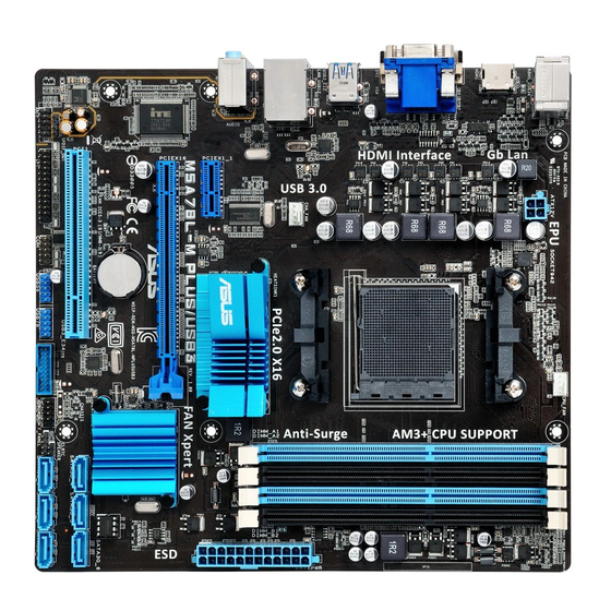
LAN_USB12 CHA_FAN Realtek ® AUDIO 8111H 760G PCIEX1_1 M5A78L-M PLUS/USB3 PCIEX16 Super ® SB710 BATTERY 16Mb BIOS 1042A CLRTC PCI1 887-VD SATA3G_4 SATA3G_5 SATA3G_6 SPDIF_OUT SATA3G_1 SATA3G_2 SATA3G_3 USB3_E34 USB56 USB78 AAFP F_PANEL SPEAKER Scan the QR code to get the detailed pin definitions. ASUS M5A78L-M PLUS/USB3... - Page 10 ATX power connectors (24-pin EATXPWR, 4-pin ATX12V) Correctly orient the ATX power supply plugs into these connectors and push down firmly until the connectors completely fit. • For a fully configured system, we recommend that you use a power supply unit (PSU) that complies with ATX 12 V Specification 2.0 (or later version) and provides a minimum power of 300 W. • If you are uncertain about the minimum power supply requirement for your system, refer to the Recommended Power Supply Wattage Calculator at http://support. asus.com/PowerSupplyCalculator/PSCalculator.aspx?SLanguage=en-us for details. CPU and chassis fan connectors (4-pin CPU_FAN, 4-pin CHA_FAN) Connect the fan cables to the fan connectors on the motherboard, ensuring that the black wire of each cable matches the ground pin of the connector. Do not forget to connect the fan cables to the fan connectors. Insufficient air flow inside the system may damage the motherboard components. These are not jumpers! Do not place jumper caps on the fan connectors! The CPU_FAN connector supports a CPU fan of maximum 2A (24 W) fan power. Only the 4-pin CPU fan supports the ASUS Fan Xpert feature. AM3+ CPU socket ® Install AMD AM3+ socket, which is designed for AMD FX™...
- Page 11 USB 3.0 connector (20-1 pin USB3_E34) Connect a USB 3.0 module to this connector for additional USB 3.0 front or rear panel ports. This connector complies with USB 3.0 specifications and provides faster data transfer speeds of up to 5 Gbps, faster charging time for USB- chargeable devices, optimized power efficiency, and backward compatibility with USB 2.0. USB 2.0 connectors (10-1 pin USB56, USB78) Connect the USB module cable to any of these connectors, then install the module to a slot opening at the back of the system chassis. These USB connectors comply with USB 2.0 specifications and support up to 480Mbps connection speed. Serial port connector (10-1 pin COM) This connector is for a serial (COM) port. Connect the serial port module cable to this connector, then install the module to a slot opening at the back of the system chassis. LPT connector (26-1 pin LPT) The LPT (Line Printing Terminal) connector supports devices such as a printer. LPT standardizes as IEEE 1284, which is the parallel port interface on IBM PC- compatible computers. ASUS M5A78L-M PLUS/USB3...
- Page 12 Digital audio connector (4-1 pin SPDIF_OUT) This connector is for an additional Sony/Philips Digital Interface (S/PDIF) port. Connect the S/PDIF Out module cable to this connector, then install the module to a slot opening at the back of the system chassis. Front panel audio connector (10-1 pin AAFP) This connector is for a chassis-mounted front panel audio I/O module that supports either HD Audio or legacy AC`97 audio standard. Connect one end of the front panel audio I/O module cable to this connector. • We recommend that you connect a high-definition front panel audio module to this connector to avail of the motherboard’s high-definition audio capability. • If you want to connect a high-definition front panel audio module to this connector, set the Azalia Front Panel item in the BIOS setup to [HD Audio]. If you want to connect an AC’97 front panel audio module to this connector, set the item to [AC97]. By default, this connector is set to [HD Audio]. PCI Express slot The PCI slot supports cards such as a LAN card, SCSI card, USB card, and other cards that comply with PCI specifications. PCI Express 2.0 x16 slot This motherboard supports PCI Express x16 network cards, SCSI cards, and other cards that comply with the PCI Express specifications.
- Page 13 Speed LED Speed Activity Link Status Description Status Description No link 10Mbps connection ORANGE Linked ORANGE 100Mbps connection BLINKING Data activity GREEN 1Gbps connection LAN port Line In port (light blue). This port connects to the tape, CD, DVD player, or other audio sources. Line Out port (lime). This port connects to a headphone or a speaker. In the 2.1, 4.1, 5.1 and 7.1-channel configurations, the function of this port becomes Front Speaker Out. Microphone port (pink). This port connects to a microphone. Refer to the audio configuration table for the function of the audio ports in 2.1, 4.1, 5.1, or 7.1-channel configuration. ASUS M5A78L-M PLUS/USB3...
- Page 14 Audio 2.1, 4.1, 5.1, or 7.1-channel configuration Headset Port 4.1-channel 5.1-channel 7.1-channel 2.1-channel Light Blue (Rear panel) Line In Rear Speaker Out Rear Speaker Out Rear Speaker Out Lime (Rear panel) Line Out Front Speaker Out Front Speaker Out Front Speaker Out Pink (Rear panel) Mic In Mic In Bass/Center Bass/Center Lime (Front panel) Side Speaker Out To configure a 7.1-channel audio output: Use a chassis with HD audio module in the front panel to support a 7.1-channel audio output. USB 2.0 ports. These 4-pin Universal Serial Bus (USB) ports are for USB 2.0/1.1 devices.
-
Page 15: Central Processing Unit (Cpu)
Central Processing Unit (CPU) The motherboard comes with an AM3+ socket designed for AMD FX™ ® Series/Phenom™ II/Athlon™ II/Sempron™ 100 Series Processors. Unplug all power cables before installing the CPU. The AM3+ socket has a different pinout from the AM2+/AM2 socket. Ensure that you use a CPU designed for the AM3+ socket. The CPU fits in only one correct orientation. DO NOT force the CPU into the socket to prevent bending the pins and damaging the CPU! Installing the CPU Apply the Thermal Interface Material to the CPU heatsink and CPU before you install the heatsink and fan if necessary. ASUS M5A78L-M PLUS/USB3... -
Page 16: System Memory
Channel B DIMM_B1 & DIMM_B2 DIMM_B2 • You may install varying memory sizes in Channel A and Channel B. The system maps the total size of the lower-sized channel for the dual-channel configuration. Any excess memory from the higher-sized channel is then mapped for single-channel operation. • Always install the DIMMS with the same CAS Latency. For an optimum compatibility, we recommend that you install memory modules of the same version or data code (D/C) from the same vendor. Check with the vendor to get the correct memory modules. • Due to the memory address limitation on 32-bit Windows OS, when you install 4GB ® or more memory on the motherboard, the actual usable memory for the OS can be about 3GB or less. For effective use of memory, we recommend that you do any of the following: Use a maximum of 3 GB system memory if you are using a 32-bit Windows OS. ® I nstall a 64-bit Windows OS if you want to install 4GB or more on the ® motherboard. F or more details, refer to the Microsoft support site at http://support.microsoft. ® com/kb/929605/en-us. • This motherboard does not support DIMMs made up of 512Mb (64MB) chips or less. Visit the ASUS website at www.asus.com for the latest QVL. Chapter 1: Product introduction... - Page 17 Installing a DIMM To remove a DIMM ASUS M5A78L-M PLUS/USB3...
-
Page 18: Chapter 2 Bios Information
Entering BIOS Setup after POST To enter BIOS Setup after POST: • Press <Ctrl>+<Alt>+<Del> simultaneously. • Press the reset button on the system chassis. • Press the power button to turn the system off then back on. Do this option only if you failed to enter BIOS Setup using the first two options. Using the power button, reset button, or the <Ctrl>+<Alt>+<Del> keys to force reset from a running operating system can cause damage to your data or system. We recommend you always shut down the system properly from the operating system. • The BIOS setup screens shown in this section are for reference purposes only, and may not exactly match what you see on your screen. • Visit the ASUS website at www.asus.com to download the latest BIOS file for this motherboard. • If the system becomes unstable after changing any BIOS setting, load the default settings to ensure system compatibility and stability. Select the Load Optimized Defaults item under the Exit menu or press hotkey F5. • If the system fails to boot after changing any BIOS setting, try to clear the CMOS and reset the motherboard to the default value. See section Motherboard overview for information on how to erase the RTC RAM. ASUS M5A78L-M PLUS/USB3... -
Page 19: Bios Menu Screen
BIOS menu screen Menu bar Menu items Configuration fields General help M5A78L-M PLUS/USB3 BIOS Setup Version 0202 Main Advanced Power Boot Tools Exit Select the ACPI state Power Settings used for System Suspend. Suspend Mode [Auto] ACPI 2.0 Support [Enabled] ACPI APIC support [Enabled] APM Configuration... - Page 20 Menu items The highlighted item on the menu bar displays the specific items for that menu. For example, selecting Main shows the Main menu items. The other items (Advanced, Power, Boot, Tools, and Exit) on the menu bar have their respective menu items. Submenu items A solid triangle before each item on a menu screen means that the item has a submenu. To display the submenu, select the item and press <Enter>. Configuration fields These fields show the values for the menu items. If an item is user- configurable, you can change the value of the field opposite the item. You cannot select an item that is not user-configurable. A configurable field is enclosed in brackets, and is highlighted when selected. To change the value of a field, select it then press <Enter> to display a list of options. Pop-up window Select a menu item then press <Enter> to display a pop-up window with the configuration options for that item. General help At the top right corner of the menu screen is a brief description of the selected item. ASUS M5A78L-M PLUS/USB3...
-
Page 21: Exit Menu
Search on FAQ Move your mouse over this button to show a QR code. Scan this QR code with your mobile device to connect to the ASUS BIOS FAQ web page. You can also scan the QR code below. Exit menu The Exit menu items allow you to load the optimal default values for the BIOS items, and save or discard your changes to the BIOS items. M5A78L-M PLUS/USB3 BIOS Setup Version 0202 Main Advanced Power Boot Tools Exit Exit Options Exit system setup after saving the cahnges. Exit & Save Changes Exit & Discard Changes F10 key can be used Discard Changes for this operation. -
Page 22: Appendix
Consult the dealer or an experienced radio/TV technician for help. The use of shielded cables for connection of the monitor to the graphics card is required to assure compliance with FCC regulations. Changes or modifications to this unit not expressly approved by the party responsible for compliance could void the user’s authority to operate this equipment. ASUS M5A78L-M PLUS/USB3... - Page 23 IC: Canadian Compliance Statement Complies with the Canadian ICES-003 Class B specifications. This device complies with RSS 210 of Industry Canada. This Class B device meets all the requirements of the Canadian interference-causing equipment regulations. This device complies with Industry Canada license exempt RSS standard(s). Operation is subject to the following two conditions: (1) this device may not cause interference, and (2) this device must accept any interference, including interference that may cause undesired operation of the device.
- Page 24 ASUS Recycling/Takeback Services ASUS recycling and takeback programs come from our commitment to the highest standards for protecting our environment. We believe in providing solutions for you to be able to responsibly recycle our products, batteries, other components as well as the packaging materials.
- Page 25 доступний на: www.asus.com/support Cijeli tekst EU izjave o sukladnosti dostupan je na: www.asus.com/support Türkçe AsusTek Computer Inc., bu aygıtın temel gereksinimlerle ve ilişkili Čeština Společnost ASUSTeK Computer Inc. tímto prohlašuje, že toto Yönergelerin diğer ilgili koşullarıyla uyumlu olduğunu beyan eder.
-
Page 26: Asus Contact Information
+1-510-739-3777 +1-510-608-4555 Web site http://www.asus.com/us/ Technical Support Support fax +1-812-284-0883 Telephone +1-812-282-2787 Online support http://qr.asus.com/techserv ASUS COMPUTER GmbH (Germany and Austria) Address Harkort Str. 21-23, 40880 Ratingen, Germany +49-2102-959931 Web site http://www.asus.com/de Online contact http://eu-rma.asus.com/sales Technical Support Telephone +49-2102-5789555 Support Fax... - Page 27 DECLARATION OF CONFORMITY Per FCC Part 2 Section 2. 1077(a) Asus Computer International Responsible Party Name: , CA 94539. Address: 800 Corporate Way, Fremont Phone/Fax No: (510)739-3777/(510)608-4555 hereby declares that the product Product Name : Motherboard Model Number : M5A78L-M PLUS/USB3...