Table of Contents
Advertisement
Quick Links
Advertisement
Table of Contents

Related Manuals for Rinnai RDV3611ETRN


Summary of Contents for Rinnai RDV3611ETRN
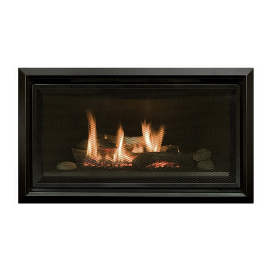
- Page 1 Models: RDV3611ETRN / RDV3611ETRL Symmetry gas fireplace Installation guide...
- Page 2 Important Appliance must be installed with a Rinnai approved flue system. This appliance shall be installed in accordance with: Manufacturer’s installation instructions Current: AS/NZS 5601 Gas Installations AS/NZS 5263 Gas Appliances General Requirements AS/NZS 3000 Electrical Standards AS/NZS 3500 Plumbing and Drainage Standards Installation, servicing and repair shall be carried out only by authorised personnel.
-
Page 3: Table Of Contents
The Symmetry RDV3611 is recommended for a new build installation into a false (mock) chimney. It is not suitable for retrofitting into an existing masonry fireplace. Appliance, including the flue, is installed after framing and before cladding. Rinnai strongly recommend the appliance is fully tested BEFORE any material is applied, as installation problems... -
Page 4: Specification
Maximum flue height is 5.4 m. a glass front and convection fan (top Appliance must be installed with a Rinnai flue system. Smaller rooms will heat up quickly, discharge). Operated with a remote and due to the efficiency of the control (7-day programmable timer). -
Page 5: Gas Supply
If the supply cord is damaged, it must be replaced by a licensed tradesperson. This must be a genuine replacement part available from Rinnai. * Consult a qualified electrician if direct wiring is required as it must comply with AS/NZS 5601.1 and AS/NZS 3000 and other relevant local regulations. -
Page 6: Framing Dimensions
Framing dimensions Enclosure dimensions W-width 1100-1125 mm* 850 mm min. H-height D-depth 540 mm min. S - side clearance * If installing a Symmetry heat transfer kit allow for an additional 250 mm side clearance per kit. For example if one kit is being installed the width would need to be 1350-1375 mm. -
Page 7: Clearances From Combustibles
Clearances from combustibles The clearances listed below, measured from the edge of the inner glass, are minimum clearances unless otherwise stated. While the heater is operating The appliance must not be installed where curtains or other combustible materials could come into contact with the heater. The 400 mm side clearance includes side walls. - Page 8 The below diagram is to assist people who are determining the clearance area around the Symmetry without having the unit on site. Symmetry 3611 1700 mm Minimum to ceiling Minimum above fire 400 mm 900 mm 400 mm Clearance Glass width Clearance 8 | Symmetry RDV3611 installation guide 11156-H 08-21...
-
Page 9: Tv Installation
TV installation with the TV manufacturer—some have warranty conditions that state a TV is not to be installed above a fireplace. Rinnai does not accept any responsibility for damage to a TV resulting from the use of this information. 400 mm... -
Page 10: Installation Overview
Installation overview Read these instructions to get an overview of the steps required before starting the installation. Failure to follow these instructions could cause a malfunction of the appliance. This could result in serious injury and/or property damage. Unpack the appliance and components, and check for damage. Do not install any damaged parts. Check all components have been supplied and that you have the correct gas type. -
Page 11: Mounting Bracket Installation
Mounting bracket installation Install the four mounting brackets supplied onto the unit. The position of the thickness will depend on the cladding thickness and the type of installation (framed or frameless). The Symmetry can be installed with granite and metal frames, and also as a frameless installation. -
Page 12: Installing The Symmetry And Fixing To The Frame
Installing the Symmetry and fixing to the frame The Symmetry comes pre-assembled with the burner already in position. For all installations the unit MUST BE positioned on a level surface 1. Position the unit inside the cavity. 2. Bend and secure the two metal standoffs supplied with the unit into position on top of the unit. -
Page 13: Cladding
Cladding When installing the cladding* ensure it is installed up to the flange and not over it. Any overhang will affect performance of the appliance and cause an unsafe situation. Cladding MUST NOT extend lower than the cladding support bracket. IMPORTANT Enclosure framework... -
Page 14: Flue Restrictor Installation
Flue restrictor installation The flue restrictor works by limiting the amount of air required for combustion. The higher the flue, the more the air is circulated. This can affect the performance of the fire. Different flue configurations require different positioning of the flue restrictor—refer to p. 24-25 to determine what setting is required. -
Page 15: Log Set Installation
Log set installation The log set is packaged separately and consists of five log pieces and three moulded rocks. Use extreme care when handling the log pieces, they are made from fragile material and will damage easily. Use these instructions in conjunction with the log location guide, which is attached to the engine. - Page 16 3. Fit the front middle left log (whale tail in the front) into the back flat section of the burner, and swing over so that it slots on top of the front base left log. 4. Place the y-shaped log securely in the back recess of the burner (there is a cutout in the log and in the back of the burner)—it will almost...
-
Page 17: Commissioning
Commissioning The gas pressures of the appliance are factory set and will normally not require adjustment. When checking the operating pressures the combustion chamber glass must be on. If installing an LPG unit with a vertical flue termination, the appliance must be uprated to 33 MJ/h using the uprating kit and instructions supplied with the unit. -
Page 18: Test Operation And Lighting Sequence
It is the responsibility of the installer to check that under normal conditions of the appliance, all flue gases are exhausted to the outside atmosphere and that there is no spillage of combustion gases into the room. If the appliance cannot be made to perform correctly please contact Rinnai. Normal flame pattern Abnormal flame pattern... -
Page 19: Fitting The Frames And Optional Dress Guard
Fitting the frames and optional dress guard The installation steps vary depending on the type of frame selected, bevelled, premium flat, granite, or inner frame only for frameless installations. For steps on how to install the frame refer to the separate installation instruction provided with each frame kit. -
Page 20: Wiring Diagram
FLAME ROD IGNITION PACK 579 DBC SIT TEST CONNECTION (BROWNN) (BROWN) Flame Rod CONTROL PANEL RECEIVER Sparker Earth (GRN/YLW) Sparker Modulating Coil (YELLOW) (Gas Control) (YELLOW) (GREY) (GREY) 12 11 10 9 8 7 6 (BLACK) High Speed Medium Speed (GRN/YLW) FAN MOTOR (BLUE) - Page 21 Symmetry flueing Symmetry RDV3611 installation guide 11156-H 08-21 | 21...
-
Page 22: General Flueing Guidelines
Flue clearance to combustibles The Rinnai Symmetry RDV3611 flue is made up of an inner flue with a protective outer flue (heat shield). It is the inner flue that gets hot, 70 mm air space requiring clearance to a combustible surface. - Page 23 Supporting the flue is usually completed during the framing stage with flue supports or straps within the cavity. Wall straps have been included in the Rinnai Vertical Flue Kits. Elbow straps are also available as a separate component to prevent excess weight on the Self-supporting flue using a wall strap flue elbow.
-
Page 24: Flueing Options
Flueing options - vertical termination Max. Max. 5.4m 5.4 m Restrictor Restrictor position # 2 position # 2 4.2 m 4.2 m Restrictor Restrictor position # 3 position # 3 3.0 m 3.0 m Restrictor Restrictor position # 4 position # 4 1.8 m 1.8 m restrictor... - Page 25 Flueing options - horizontal termination For example: Vertical flue: 5.0 m (6.03-5.0) � 0.52 Max. 1.2 m Max horiz. flue: 2.0 m Max. 5.4 m Restrictor position # 3 Restrictor position # 3 4.2 m Restrictor position # 4 2.4 m No restrictor For example: Vertical flue:...
-
Page 26: Symmetry Rdv3611 Flue Kits
Symmetry RDV3611 flue kits Symmetry RDV3611 flue kits have been based on the flue configurations shown. If you have a combined vertical and horizontal flue configuration you can order separate components to suit. RDV3611 Flue Kit Horizontal (short, R3660) RDV3611 Flue Kit Vertical 3.6 m (R3665) 1. -
Page 27: Symmetry Rdv3611 Horizontal Flue Kits
Symmetry RDV3611 horizontal flue kits The following diagram explains the components, dimensions (mm), and appropriate flue kits available for differing horizontal flue installations. Refer to the table below to calculate what flue pipe length and/or kit you may need. RDV3611 Short Horiz. Flue Kit A (R3660) RDV3611 Long Horiz. -
Page 28: Symmetry Rdv3611 Flue Components
Symmetry RDV3611 flue components RDV3611 flue pipes Flue extension Roof cowl (R3651) Aluminium flue terminal required 150 mm: R3630 75-175 mm: R3638 for all vertical flue installations. 230 mm: R3631 75-360 mm: R3639 300 mm: R3632 268 mm 450 mm: R3633 Used for extended straight lengths of flue. - Page 29 Horizontal flashing kit (R3646) Wall strap (R3647) Elbow strap (R3644) Flashing components used to join Adjustable strap used in interior/ Flue support for elbow and the internal flue to the outside flue— offsets. exterior installations to add lateral support to the flue. Refer horizontal wall terminal for installed dimensions.
-
Page 30: Horizontal Termination Example
Horizontal termination example flue components required 1. Flue pipe 900 mm (R3635) 2. Wall strap (R3647) 3. 90 º bend (R3643) 4. Flue pipe* 5. Horiz. flashing kit (R3646) 6. Horiz. wall terminal (R3650) * Size of flue pipe will depend on the installation. -
Page 31: Vertical Termination Example
Vertical termination example flue components required 1. Flue pipe 150 mm (R3630) 2. Flue pipe 1200 mm (R3636) 3. Wall strap (R3647) 4. Roof cowl (R3651) Symmetry RDV3611 540 mm min. Symmetry RDV3611 installation guide 11156-H 08-21 | 31... - Page 32 Rinnai.co.nz Tel: 0800 746 624 http://www.youtube.com/rinnainz Symmetry RDV3611 installation guide: 11156-H http://facebook.com.rinnainz...