Table of Contents
Advertisement
Quick Links
MODEL G0945/G0946/G0947
6" & 8" BENCHTOP JOINTERS
OWNER'S MANUAL
(For models manufactured since 06/21)
(G0947)
(G0945)
(G0946)
COPYRIGHT © JULY, 2021 BY GRIZZLY INDUSTRIAL, INC.
WARNING: NO PORTION OF THIS MANUAL MAY BE REPRODUCED IN ANY SHAPE
OR FORM WITHOUT THE WRITTEN APPROVAL OF GRIZZLY INDUSTRIAL, INC.
#KS21841 PRINTED IN TAIWAN
V1.07.21
Advertisement
Table of Contents

Related Manuals for Grizzly G0945


Summary of Contents for Grizzly G0945
- Page 1 (For models manufactured since 06/21) (G0947) (G0945) (G0946) COPYRIGHT © JULY, 2021 BY GRIZZLY INDUSTRIAL, INC. WARNING: NO PORTION OF THIS MANUAL MAY BE REPRODUCED IN ANY SHAPE OR FORM WITHOUT THE WRITTEN APPROVAL OF GRIZZLY INDUSTRIAL, INC. #KS21841 PRINTED IN TAIWAN V1.07.21...
- Page 2 This manual provides critical safety instructions on the proper setup, operation, maintenance, and service of this machine/tool. Save this document, refer to it often, and use it to instruct other operators. Failure to read, understand and follow the instructions in this manual may result in fire or serious personal injury—including amputation, electrocution, or death.
-
Page 3: Table Of Contents
Identification ........... 3 Cleaning & Protecting ........32 Controls & Components ......... 4 Lubrication ........... 32 G0945 Machine Data Sheet ......5 G0946 Machine Data Sheet ......7 SECTION 7: SERVICE ........33 G0947 Machine Data Sheet ......9 Troubleshooting ........... 33 Rotating/Replacing Inserts (G0946/G0947) . -
Page 4: Introduction
ID label (see below). This information is required for us to provide proper tech support, and it helps us determine if updated documentation is available for your machine. Manufacture Date Serial Number Model G0945/G0946/G0947 (Mfd. Since 06/21) -
Page 5: Identification
⁄ " in one pass. d) Always use hold-down or push blocks when jointing material narrower than 3" or planing material thinner than 3". e) Never perform cuts on pieces shorter than 10" in length. Model G0945/G0946/G0947 (Mfd. Since 06/21) -
Page 6: Controls & Components
M. Fence Tilt Lock Handle: Secures fence tilt cut. angle. Fence tilt can be adjusted between 90º–135º. ALWAYS tighten lock before begin- D. Infeed Table Adjustment Knob: Adjusts ning operations. height of infeed table to control depth of cut. Model G0945/G0946/G0947 (Mfd. Since 06/21) -
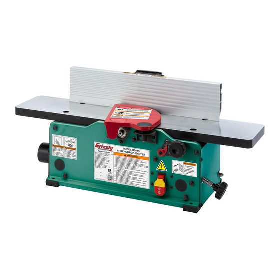
Page 7: G0945 Machine Data Sheet
MACHINE DATA SHEET Customer Service #: (570) 546-9663 · To Order Call: (800) 523-4777 · Fax #: (800) 438-5901 MODEL G0945 6" BENCHTOP JOINTER Product Dimensions: Weight................................43 lbs. Width (side-to-side) x Depth (front-to-back) x Height..............30 x 17-1/2 x 13 in. - Page 8 The information contained herein is deemed accurate as of 7/25/2021 and represents our most recent product specifications. Model G0945 PAGE 2 OF 2 Due to our ongoing improvement efforts, this information may not accurately describe items previously purchased. Model G0945/G0946/G0947 (Mfd. Since 06/21)
-
Page 9: G0946 Machine Data Sheet
The information contained herein is deemed accurate as of 7/25/2021 and represents our most recent product specifications. Model G0946 PAGE 1 OF 2 Due to our ongoing improvement efforts, this information may not accurately describe items previously purchased. Model G0945/G0946/G0947 (Mfd. Since 06/21) - Page 10 The information contained herein is deemed accurate as of 7/25/2021 and represents our most recent product specifications. Model G0946 PAGE 2 OF 2 Due to our ongoing improvement efforts, this information may not accurately describe items previously purchased. Model G0945/G0946/G0947 (Mfd. Since 06/21)
-
Page 11: G0947 Machine Data Sheet
The information contained herein is deemed accurate as of 7/25/2021 and represents our most recent product specifications. Model G0947 PAGE 1 OF 2 Due to our ongoing improvement efforts, this information may not accurately describe items previously purchased. Model G0945/G0946/G0947 (Mfd. Since 06/21) - Page 12 The information contained herein is deemed accurate as of 7/25/2021 and represents our most recent product specifications. Model G0947 PAGE 2 OF 2 Due to our ongoing improvement efforts, this information may not accurately describe items previously purchased. -10- Model G0945/G0946/G0947 (Mfd. Since 06/21)
-
Page 13: Section 1: Safety
Never operate under the influence of drugs or injury or blindness from flying particles. Everyday alcohol, when tired, or when distracted. eyeglasses are NOT approved safety glasses. -11- Model G0945/G0946/G0947 (Mfd. Since 06/21) - Page 14 Make sure they are properly installed, you experience difficulties performing the intend- undamaged, and working correctly BEFORE ed operation, stop using the machine! Contact our operating machine. Technical Support at (570) 546-9663. -12- Model G0945/G0946/G0947 (Mfd. Since 06/21)
-
Page 15: Additional Safety For Jointers
Straight knives should never project MAXIMUM CUTTING DEPTH. To reduce risk of more than ⁄ " (0.125") from cutterhead body. kickback, never cut deeper than ⁄ " per pass. -13- Model G0945/G0946/G0947 (Mfd. Since 06/21) -
Page 16: Section 2: Power Supply
-14- Model G0945/G0946/G0947 (Mfd. Since 06/21) - Page 17 Two-prong outlets do not meet the grounding requirements for this machine. Do not modify or use an adapter on the plug provided—if it will not fit the outlet, have a qualified electrician install the proper outlet with a verified ground. -15- Model G0945/G0946/G0947 (Mfd. Since 06/21)
-
Page 18: Section 3: Setup
Like all machinery there is potential danger you are completely satisfied with the machine and when operating this machine. Accidents are have resolved any issues between Grizzly or the frequently caused by lack of familiarity or shipping agent. You MUST have the original pack- failure to pay attention. -
Page 19: Inventory
T-Slot Nuts 7, M6-1 ........2 Square Nut M8-1.25 ........1 K. Fence Slide Lock Handle ......1 L. Hex Wrenches 2.5, 4mm ....... 1 Ea. M. T-Handle Torx Wrench T-25 (G0946/G0947) .. 1 N. Push Blocks ..........2 -17- Model G0945/G0946/G0947 (Mfd. Since 06/21) -
Page 20: Cleanup
Avoid harsh solvents like acetone or brake or disable start switch or parts cleaner that may damage painted sur- power connection to prevent faces. Always test on a small, inconspicu- unsupervised use. ous location first. -18- Model G0945/G0946/G0947 (Mfd. Since 06/21) -
Page 21: Bench Mounting
Fence Slide Bracket Lag Screw Flat Washer Machine Base T-Slot Nut (1 of 2) Workbench Figure 10. Button head cap screws and Figure 8. "Direct Mount" setup. T-slot nuts installed. -19- Model G0945/G0946/G0947 (Mfd. Since 06/21) - Page 22 Slide Square Nut Bracket Fence Slide Fence Bracket Center Support Fence Cutout Bracket Figure 12. Fence cutout aligned with center of fence slide bracket. Figure 14. Square nut installed on fence slide lock handle. -20- Model G0945/G0946/G0947 (Mfd. Since 06/21)
-
Page 23: Dust Collection
Figure 16. Dust hose attached to dust port. Tug the hose to make sure it does not come off. Note: A tight fit is necessary for proper dust collection performance. Dust Port Figure 15. Dust port installed on jointer. -21- Model G0945/G0946/G0947 (Mfd. Since 06/21) -
Page 24: Test Run
Clear all setup tools away from machine. jointer before operating or damage to machine may G0945 Only: Disengage cutterhead lock. occur! Connect machine to power supply. Turn machine ON, verify motor operation, During the first 16 hours, the belt will stretch and then turn machine OFF. -
Page 25: Section 4: Operations
Read books/magazines or get formal training before beginning any proj- ects. Regardless of the content in this sec- tion, Grizzly Industrial will not be held liable for accidents caused by lack of training. -23- Model G0945/G0946/G0947 (Mfd. Since 06/21) -
Page 26: Stock Inspection
1" Min. glass, stone, tile, products with lead-based paint, or products that contain asbestos. Cutting Figure 19. Minimum stock dimensions for jointer. these may lead to injury or machine damage. Surface Planing -24- Model G0945/G0946/G0947 (Mfd. Since 06/21) 10" Min. -
Page 27: Setting Depth Of Cut
(see Figure 20). Table Height Lock Knob Depth-of-Cut Scale Pointer Button Head Cap Screw Figure 22. Location of depth-of-cut components. Depth-of-Cut Infeed Table Scale Adjustment Knob Figure 20. Location of depth-of-cut controls. -25- Model G0945/G0946/G0947 (Mfd. Since 06/21) -
Page 28: Squaring Stock
4. Rip Cut on a Table Saw—The jointed edge the jointer. of the workpiece is placed against a table saw fence and the opposite edge cut off. Previously Jointed Edge -26- Model G0945/G0946/G0947 (Mfd. Since 06/21) -
Page 29: Surface Planing
Repeat Step 6 until entire surface is flat. Tip: When squaring up stock, cut opposite side of workpiece with a planer instead of the jointer to ensure boths sides are parallel. Removed Surface Figure 23. Example of a surface planing operation. -27- Model G0945/G0946/G0947 (Mfd. Since 06/21) -
Page 30: Edge Jointing
Repeat Step 6 until the entire edge is flat. operation. Tip: When squaring up stock, cut opposite edge of workpiece with a table saw instead of the jointer—otherwise, both edges of work- piece will not be parallel with each other. -28- Model G0945/G0946/G0947 (Mfd. Since 06/21) -
Page 31: Bevel Cutting
Figure 25. Example of fence set up for a bevel than 4" from moving cutterhead at any time cut of 45°. during operation! Repeat cutting process, as necessary, until you are satisfied with the results. -29- Model G0945/G0946/G0947 (Mfd. Since 06/21) -
Page 32: Section 5: Accessories
Assembly is fast and easy with bolt-together legs and supports along pre-drilled holes in the work- T32900—SK5 Steel Jointer Knives (2 Pack) bench tops. Replacement knives for the G0945 jointer. These SK5 steel jointer knives measure 6 ⁄ " x ⁄... - Page 33 These adaptors will allow you to connect the 2 ⁄ " G3591—30 Micron Replacement Bag dust port on the G0945/G0946 jointers to a dust H4340—3.0 Micron Upgrade Bag collection system with standard 3" or 4" fittings. Excellent point-of-use dust collectors that can be used next to the machine with only a small amount of ducting.
-
Page 34: Section 6: Maintenance
Keep your table rust-free with regular applications of quality lubricants. Wax and buff Move components along their full range of motion table surface to help prevent improper feeding of several times, then wipe off any excess oil. workpiece. -32- Model G0945/G0946/G0947 (Mfd. Since 06/21) -
Page 35: Section 7: Service
5. Adjust feet, shim, or tighten mounting hardware. 6. Motor mount loose/broken. 6. Tighten/replace. 7. Cutterhead bearing(s) at fault. 7. Replace bearing(s)/realign cutterhead. 8. Motor bearings at fault. 8. Test by rotating shaft; rotational grinding/loose shaft requires bearing replacement. -33- Model G0945/G0946/G0947 (Mfd. Since 06/21) - Page 36 1. Table lock engaged/partially engaged. 1. Completely loosen table lock. adjust. Excessive 1. Outfeed table is set too low, or knives (G0945 1. Align outfeed table with cutterhead knives/inserts at snipe (gouge only) set too high. top dead center (Page 39).
- Page 37 3. Adjust knives so they are set up evenly in cutterhead in cutterhead. (Page 38). Remove, clean, and re-install any inserts that are "raised" in cutterhead (Page 36). 4. Table extensions not parallel with tables. 4. Check/adjust table extension parallelism (Page 43). -35- Model G0945/G0946/G0947 (Mfd. Since 06/21)
-
Page 38: Rotating/Replacing Inserts (G0946/G0947)
T-Handle Torx Driver T-25 ......... 1 Hex Wrench 4mm ..........1 Torque Wrench 0–50 in.-lb ........ 1 Degreaser .......... As Needed Light Machine Oil....... As Needed Clean Shop Rags ......As Needed Figure 34. Cutterhead area cleaned. -36- Model G0945/G0946/G0947 (Mfd. Since 06/21) -
Page 39: Checking/Setting Knives (G0945)
Install cutterhead guard removed in Step 3 on Page 36. -37- Model G0945/G0946/G0947 (Mfd. Since 06/21) - Page 40 Proceed to Step 6. Note: Clean cutterhead thoroughly before Straightedge installing new or sharpened knives. Outfeed Infeed Figure 36. Checking knife height at top dead center with a straightedge. Figure 38. Cutterhead knife clamp screws. -38- Model G0945/G0946/G0947 (Mfd. Since 06/21)
-
Page 41: Checking/Adjusting Table Parallelism
Although some figures might not exactly represent your machine, this process is the When knife heights are set correctly, fully same on the G0945, G0946, and G0947. tighten each of the knives' clamp screws according to the tightening sequence shown Items Needed in Figure 40. - Page 42 Table Parallelism on Page 41. Straightedge Positions From Overhead View Black Lines Represent Straightedge Positions from Overhead View Figure 42. Straightedge positions for verifying outfeed table parallelism. Figure 44. Example of infeed and outfeed table height set evenly. -40- Model G0945/G0946/G0947 (Mfd. Since 06/21)
- Page 43 Figure 46. Example of outfeed table leveling these parts to reduce risk of personal injury. adjuster location. Although some figures might not exactly represent your machine, this process is the same on the G0945, G0946, and G0947. -41- Model G0945/G0946/G0947 (Mfd. Since 06/21)
- Page 44 Steps 2 & 7 in infeed and outfeed table openings. 11. Install fence (if removed) and cutterhead guard, then verify proper operation. 12. G0947 Only: Proceed to Checking/Adjusting Extension Parallelism on Page 43. -42- Model G0945/G0946/G0947 (Mfd. Since 06/21)
-
Page 45: (G0947)
Knob (1 of 2) sion handle, then table extension is not parallel with table. Repeat Step 4. Leveling Collar Lock Screws Retract table extension and tighten (2) table extension knobs. Figure 51. Location of table extension components. -43- Model G0945/G0946/G0947 (Mfd. Since 06/21) -
Page 46: Checking/Adjusting Fence Positive Stops
Adjust fence until it is flush against combina- represent your machine, this process is the tion square, then tighten 90º set screw on same on the G0945, G0946, and G0947. fence slide bracket until it contacts stop block (see Figure 54). - Page 47 — If fence is flush against combination square, fence positive stops are set correctly. — If fence is not flush against combination square, perform Steps 5–10 to properly set fence positive stops. -45- Model G0945/G0946/G0947 (Mfd. Since 06/21)
-
Page 48: Replacing/Tensioning Belt
Motor Pulley Figure 58. Checking ⁄ " belt deflection. Install belt cover using (1) button head cap screw removed in Step 2 of Replacing Belt. Figure 57. Location of screws around motor pulley. -46- Model G0945/G0946/G0947 (Mfd. Since 06/21) -
Page 49: Replacing Motor Brushes
Refer to Troubleshooting on Page 33 for assistance. Note: Place clean shop rags under jointer to help prevent damaging machine finish. Vacuum all dust and debris from motor area. -47- Model G0945/G0946/G0947 (Mfd. Since 06/21) -
Page 50: Section 8: Wiring
Technical Support at (570) 546-9663. The photos and diagrams included in this section are best viewed in color. You can view these pages in color at www.grizzly.com. -48- Model G0945/G0946/G0947 (Mfd. Since 06/21) -
Page 51: Wiring Diagram
(viewed from behind) SHOCK HAZARD! PADDLE SWITCH Disconnect power KEDU HY18 20A before working on wiring Ground To Power Connection Paddle Motor Switch Paddle Switch Figure 60. Wiring overview. READ ELECTRICAL SAFETY -49- Model G0945/G0946/G0947 (Mfd. Since 06/21) ON PAGE 48! -
Page 52: Section 9: Parts
SECTION 9: PARTS We do our best to stock replacement parts when possible, but we cannot guarantee that all parts shown are available for purchase. Call (800) 523-4777 or visit www.grizzly.com/parts to check for availability. G0945 Main 160-3 160-4 160-5... - Page 53 PADDLE SWITCH ASSEMBLY P0945058 ADJUSTMENT ROD 323-1 P0945323-1 PADDLE SWITCH KEDU HY18 20A P0945059 ADJUSTMENT SHAFT 323-2 P0945323-2 PADDLE SWITCH COVER BUY PARTS ONLINE AT GRIZZLY.COM! -51- Model G0945/G0946/G0947 (Mfd. Since 06/21) Scan QR code to visit our Parts Store.
-
Page 54: G0946 Main
G0946 Main 43-2 43-1 43-1 43-2 160-1 160-2 160-3 300-1 300-2 300-3 14 16 57 56 323-2 323-1 BUY PARTS ONLINE AT GRIZZLY.COM! -52- Model G0945/G0946/G0947 (Mfd. Since 06/21) Scan QR code to visit our Parts Store. - Page 55 P0946056 SET SCREW M6-1 X 16 DOG-PT 323-2 P0946323-2 PADDLE SWITCH COVER P0946057 HEX NUT M6-1 323-3 P0946323-3 PADDLE SWITCH KEY BUY PARTS ONLINE AT GRIZZLY.COM! -53- Model G0945/G0946/G0947 (Mfd. Since 06/21) Scan QR code to visit our Parts Store.
-
Page 56: G0947 Main
43-2 43-1 43-3 43-9 43-4 43-6 43-7 43-8 43-5 160-1 160-2 160-3 300-1 300-2 300-3 14 16 57 56 323-2 323-1 BUY PARTS ONLINE AT GRIZZLY.COM! -54- Model G0945/G0946/G0947 (Mfd. Since 06/21) Scan QR code to visit our Parts Store. - Page 57 STUD-DE M6-1 X 150, 12 323-1 P0947323-1 PADDLE SWITCH KEDU HY18 20A P0947050 POWER CORD CLAMP 323-2 P0947323-2 PADDLE SWITCH COVER BUY PARTS ONLINE AT GRIZZLY.COM! -55- Model G0945/G0946/G0947 (Mfd. Since 06/21) Scan QR code to visit our Parts Store.
-
Page 58: Labels & Cosmetics
Safety labels help reduce the risk of serious injury caused by machine hazards. If any label comes off or becomes unreadable, the owner of this machine MUST replace it in the original location before resuming operations. For replacements, contact (800) 523-4777 or www.grizzly.com. BUY PARTS ONLINE AT GRIZZLY.COM! -56- Model G0945/G0946/G0947 (Mfd. -
Page 59: Warranty & Returns
WARRANTY & RETURNS Grizzly Industrial, Inc. warrants every product it sells for a period of 1 year to the original purchaser from the date of purchase. This warranty does not apply to defects due directly or indirectly to misuse, abuse, negligence, accidents, repairs or alterations or lack of maintenance.