Table of Contents
Advertisement
CONTENTS
SAFETY CONSIDERATIONS . . . . . . . . . . . . . . . . . . . . . . 1
INSTALLATION . . . . . . . . . . . . . . . . . . . . . . . . . . . . . . . . 1-24
Step 1 - Rig and Place the Unit. . . . . . . . . . . . . . . . . . 1
• RIGGING
• PLACING UNIT
• MOUNTING UNIT
Step 2 - Check Compressor Mounting . . . . . . . . . . 3
Connections (Units Without
Hydronic Packages). . . . . . . . . . . . . . . . . . . . . . . . . . . . 3
OPERATION
Connections (Units With Factory-Installed
Hydronic Packages). . . . . . . . . . . . . . . . . . . . . . . . . . . 12
Step 5 - Make Electrical Connections . . . . . . . . . . 18
Step 6 - Install Accessories . . . . . . . . . . . . . . . . . . . . 18
• ELECTRICAL
Step 7 - Refrigerant Circuit. . . . . . . . . . . . . . . . . . . . . 24
• LEAK TESTING
• DEHYDRATION
APPENDIX A (Pressure Drop Curves,
30RA010-055) . . . . . . . . . . . . . . . . . . . . . . . . . . . . . . 25-27
SAFETY CONSIDERATIONS
Installing, starting up, and servicing air-conditioning equip-
ment can be hazardous due to system pressures, electrical
components, and equipment location (roofs, elevated struc-
tures, etc.).
Only trained, qualified installers and service mechanics
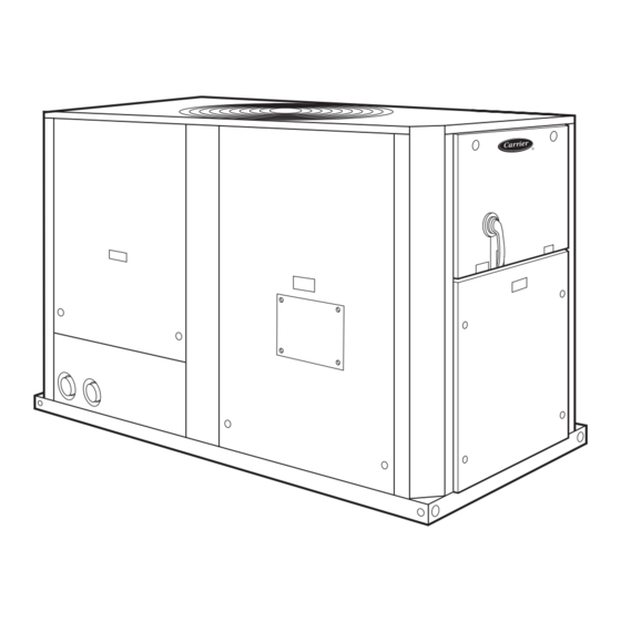
should install, start up, and service this equipment (Fig. 1).
Untrained personnel can perform basic maintenance func-
tions such as cleaning coils. All other operations should be
performed by trained service personnel.
When working on the equipment, observe precautions in the
literature and on tags, stickers, and labels attached to the
equipment.
• Follow all safety codes.
• Wear safety glasses and work gloves.
• Keep quenching cloth and fire extinguisher nearby when
brazing.
• Use care in handling, rigging, and setting bulky
equipment. See Tables 1A-1D for Physical Data. Refer
to Fig. 2 for unit weights.
Manufacturer reserves the right to discontinue, or change at any time, specifications or designs without notice and without incurring obligations.
PC 903
Catalog No. 533-00045
Book 2
Tab
5c
Installation Instructions
Page
Printed in U.S.A.
TM
AquaSnap
With ComfortLink
ELECTRIC SHOCK HAZARD
Open all remote disconnects before servicing
this equipment.
INSTALLATION
Step 1 - Rig and Place the Unit
RIGGING - Preferred method is with spreader bars from
above the unit. Use hooks in lifting holes. Rig at a single point
with 4 cables or use spreader bars. All panels must be in place
when rigging. See rigging label on unit for details concerning
shipping weights, distance between lifting holes, center of
gravity, and lifting ring dimensions. See Fig. 3.
If overhead rigging is not possible, place chiller on skid or
pad for rolling or dragging. When rolling, use a minimum of
3 rollers. When dragging, pull the pad. Do not apply force to
the unit. When in final position, raise from above to lift unit
off pad.
All panels must be in place when rigging.
PLACING UNIT - There must be at least 3 ft (.9 m) for ser-
vice and for unrestricted airflow on all non-coil sides of unit,
and a minimum of 3.5 ft (1.1 m) clear air space on coil sides.
For multiple units, allow 8 ft (2.48 m) separation between units
for airflow and service.
MOUNTING UNIT - When unit is in proper location, use
of mounting holes in base rails is recommended for securing
unit to supporting structure, or for mounting unit on vibration
isolators if required. See Fig. 3. Fasteners for mounting unit are
field supplied. Be sure unit is level to within
proper oil return to compressor.
Fig. 1 - Typical 30RA Unit (010-018 Shown)
Form 30RA-12SI
Pg 1
30RAN010-055
Liquid Chillers
TM
Controls
50/60 Hz
1
/
in. per foot for
8
7-02
Replaces: 30RA-1SI
Advertisement
Table of Contents

Related Manuals for Carrier AquaSnap 30RAN010-055


Summary of Contents for Carrier AquaSnap 30RAN010-055
-
Page 1: Table Of Contents
30RAN010-055 AquaSnap Liquid Chillers With ComfortLink Controls 50/60 Hz Installation Instructions CONTENTS ELECTRIC SHOCK HAZARD Page Open all remote disconnects before servicing SAFETY CONSIDERATIONS ..... . 1 this equipment. - Page 2 CONTROL BOX END 60 Hz 50 Hz STD UNITS (without hydronic package) STD UNITS (without hydronic package) POUNDS — ALUMINUM POUNDS — COPPER POUNDS — ALUMINUM POUNDS — COPPER 30RA 30RA 30RA 30RA Total Total Total Total SIZE SIZE SIZE SIZE Weight Weight...
-
Page 3: Step 2 - Check Compressor Mounting
Step 2 — Check Compressor Mounting — fused disconnect. Identify disconnect as heat tape power source with a warning that power must not be turned off except when shipped, each compressor is held down by 4 bolts. After unit is unit is being serviced. - Page 4 Table 1A — Physical Data, 30RA — 60 Hz English UNIT 30RA REFRIGERANT TYPE R-22, TXV Controlled System Refrigerant Charge (lb) Ckt A/Ckt B 18/— 27/— 36/— 37/— 38/— 48/— 44/30 45/30 44/44 45/45 55/55 COMPRESSORS Scroll, Hermetic Quantity Speed (Rpm) 3500 (Qty) Ckt A (1) SM115,...
- Page 5 Table 1C — Physical Data, 30RA — 60 Hz SI UNIT 30RA R-22, TXV Controlled System REFRIGERANT TYPE Refrigerant Charge (kg) Ckt A/Ckt B 8.2/— 12.2/— 16.3/— 16.8/— 17.2/— 21.8/— 20.0/13.6 20.4/13.6 20.0/20.0 20.4/20.4 25.0/25.0 COMPRESSORS Scroll, Hermetic Quantity Speed (r/s) 58.3 (Qty) Ckt A (1) SM115,...
-
Page 12: Hydronic Packages)
Step 4 — Cooler Fluid and Drain Piping Con- nections (Units with Factory-Installed Hy- dronic Packages) WATER SYSTEM OVERVIEW — The 30RA chillers with factory-installed hydronic packages are designed for use with closed systems, meaning that there is no more than one water- air interface in the water loop. -
Page 13: Air Separation
2 feet per second will keep free air entrained and for drainage outside the unit. prevent it from forming air pockets. The Carrier ComfortLink™ controls provided have a built- Automatic vents should be installed at all physically elevat- in feature to remind building owners or operators to clean the... -
Page 14: System Pressurization
Distribution Pump Decoupler Expansion Tank(s) Air Separator with Vent NOTE: Expansion tanks in the 30RA hydronic kits must be disconnected for chillers placed parallel in the primary water loop. Fig. 12 — Typical Air Separator and Expansion Tank Location on Primary-Secondary Systems SYSTEM SYSTEM POT FEEDER AND... -
Page 15: Filling The System
FILLING THE SYSTEM — The initial fill of the chilled the flow through the balancing valve. water system must accomplish three purposes: NOTE: Carrier recommends a differential pressure gage when 1. The entire piping system must be filled with water. measuring pressures across the pumps or balancing valves. - Page 16 LEGEND LEGEND 1 — 30RA010 4 — 30RA022 7 — 30RA032, 30RA035 10 — 30RA050 2 — 30RA015 5 — 30RA025 8 — 30RA040 11 — 30RA055 3 — 30RA018 6 — 30RA030 9 — 30RA042, 30RA045 Fig. 15A — Heat Exchanger Pressure Drop — Fig.
- Page 17 Contact your local Carrier representative for a recommended machine shop. After trim- ming, the impeller MUST be balanced. Failure to balance trimmed impellers can result in excessive vibration, noise, and premature bearing failure. Impeller trimming has the added benefit of maximum BHP savings.
-
Page 18: Step 5 - Make Electrical Connections
30RA010-018 (230-3-50, 230-3-60, 208/230-3-60) Minimum Load Accessory — If minimum load accessory is 30RA035-055 (380-3-60, 460-3-60) required, refer to unit Price Pages or contact your local Carrier 30RA032-045 (380/415-3-50) 250 AMP representative for more details. For installation details, refer to... - Page 19 Table 8 — Electrical Data 2.0/1.5 HP 2.0/1.5 HP 1.5/1.0 HP PUMP 3.0/2.0 HP PUMP 5.0/3.0 HP PUMP (STD) PUMP (ALT) PUMP UNIT VOLTAGE NO HYDRONIC PACKAGE Pump Options Pump Options Pump Options POWER Pump Options Pump Options ‘A’ or ‘F’ ‘D’...
- Page 20 Table 9 — Fan Electrical Data Table 10 — Pump Electrical Data UNIT VOLTAGE STANDARD CONDENSER FANS UNIT VOLTAGE PUMP PUMP PUMP UNIT OPTION SIZE (each) (each) Circuit A Circuit B V-Hz (3 Ph) 30RA V-Hz (3 Ph) Quantity (each) Quantity (each) 3500...
- Page 21 Table 11 — Compressor Electrical Data UNIT VOLTAGE COMPRESSOR UNIT 30RA V-Hz (3 Ph) 230-60 30.9 — — — — — — 208/230-60 34.3 — — — — — — 460-60 16.0 — — — — — — 575-60 12.9 —...
-
Page 24: Step 7 - Refrigerant Circuit
Do not reuse O-rings. Repair any leak found using good refrigeration practice. DEHYDRATION — Refer to Carrier Standard Service Tech- niques Manual, Chapter 1, Refrigerants, Sections 6 and 7 for details. Do not use compressor to evacuate system. - Page 25 APPENDIX A Pressure Drop Curves, 30RA010-055 PRESSURE DROP , WITHOUT PUMP UNITS, PRESSURE DROP , WITHOUT PUMP UNITS, 30RA010-030 30RA010-030 PRESSURE DROP , WITHOUT PUMP UNITS, PRESSURE DROP , WITHOUT PUMP UNITS, 30RA032-055 30RA032-055 PRESSURE DROP , SINGLE PUMP UNITS, PRESSURE DROP , SINGLE PUMP UNITS, 30RA010-030 30RA010-030...
- Page 26 APPENDIX A (cont) Pressure Drop Curves, 30RA010-055 (cont) PRESSURE DROP , SINGLE PUMP UNITS, PRESSURE DROP , SINGLE PUMP UNITS, 30RA032-055 30RA032-055 PRESSURE DROP , DUAL PUMP UNITS, PRESSURE DROP , DUAL PUMP UNITS, SIZES 30RA010-030 SIZES 30RA010-030 PRESSURE DROP , DUAL PUMP UNITS, PRESSURE DROP , DUAL PUMP UNITS, SIZES 30RA032-055 SIZES 30RA032-055...
- Page 27 APPENDIX A (cont) Pressure Drop Curves, Accessory Storage Tanks 100.0 30RA-900---010 10.0 30RA-900---001,009 1000 ACCESSORY TANK FLOW RATE (gpm) 100.0 30RA-900---010 10.0 30RA-900---001,009 10.0 ACCESSORY TANK FLOW RATE (L/s)
-
Page 28: Printed In U.s.a. Form 30Ra-12Si Pg
Copyright 2002 Carrier Corporation Manufacturer reserves the right to discontinue, or change at any time, specifications or designs without notice and without incurring obligations. Book 2 PC 903 Catalog No. 533-00045 Printed in U.S.A. Form 30RA-12SI Pg 28 7-02 Replaces: 30RA-1SI...