
Related Manuals for Trane Tracer ZN.520


Summary of Contents for Trane Tracer ZN.520
- Page 1 CNT-SVX04A-EN Tracer ZN.520 Unit ™ Controller Installation, Operation and Programming Guide CNT-SVX04A-EN December 2000...
- Page 3 Preface The Trane Company has a policy of continuous product improvement and reserves the right to change specifications and design without notice. Only qualified technicians should install and service the equipment referred to in this document. Published by The Trane Company, La Crosse, Wisconsin. Printed in USA.
-
Page 5: Table Of Contents
Contents Introduction................3 The Trane family of Tracer zone controllers........3 Supported products .............. 4 Macon, Georgia, business unit ............4 Waco, Texas, business unit ............5 Features .................. 6 Circuit board................7 Physical specification ............8 Configurations ..............11 Binary outputs .............. - Page 6 Contents On/Cancel buttons............... 34 Communication jack ..............34 Zone sensor wiring connections ..........35 Communications ..............36 Power................... 37 Input/output summary ............38 Sequence of operation............39 Power-up sequence ..............40 Setpoint operation ............... 40 Setpoint selection................ 40 Occupied and unoccupied operation ........... 43 Occupied mode ................
- Page 7 Contents Configuration ...............72 Configurable parameter ............... 72 Application information............. 79 Stand-alone.................. 79 Stand-alone peer-to-peer ............. 80 Troubleshooting ..............83 LED operation................83 Manual output test ..............84 Diagnostics ..................88 Questionable unit operation ............92 Appendix 97 Hardwired setpoint adjustment ........... 97 Hardwired thermistor values ............
-
Page 9: Introduction
The Trane family of Tracer zone controllers The Trane family of Tracer zone controllers is the next generation of quality equipment controllers designed to meet product-specific requirements. Tracer ZN.510 and the Tracer ZN.010 were the first controls to support 2-position (on/off) control requirements of 1 heat/1 cool and water source heat pump terminal units. -
Page 10: Supported Products
Supported products Macon, Georgia, business unit The Tracer ZN.520 zone controller supports hydronic terminal units with two- position valves and dampers, and one The Trace ZN.520 zone controller is applied to the UniTrane fan-coil unit, Force- stage of electric heat. The Tracer™ ZN.520 Flo cabinet heaters, UniTraneâ... -
Page 11: Waco, Texas, Business Unit
Supported products Waco, Texas, business unit Waco offers the Tracer ZN.520 on classroom unit ventilators in horizontal or vertical configurations. Multiple sizes are available in both configurations, as shown in Table 1. Table 1 Classroom unit ventilators: size configurations Horizontal unit ventilator (HUV) -
Page 12: Features
Features Table 2 Tracer ZN.520 zone controller features and coil availability Coil Multiple Dehumid- Auto Face and Valve Economizer Auxiliary Entering ification damper bypass control damper heat water speeds adjust damper (Note 2) temperature sampling 2-pipe changeover 2-pipe hot water only... -
Page 13: Circuit Board
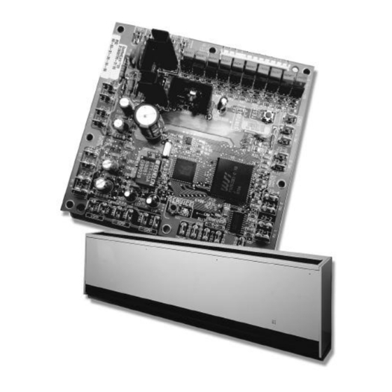
Circuit board Figure 1 Tracer ZN.520 zone controller circuit board Power Generic Auto test button Status LED Communications LED Communications LED Service button and LED Communications Zone sensor connections connections CNT-SVX04A-EN... -
Page 14: Physical Specification
Physical specifications Board dimensions Height: 5.25 in. (133 mm) Width: 5.50 in. (140 mm) Depth: 2.25 in. (57 mm) Operating environment 32° to 140°F (0° to 60°C) 5% to 95% relative humidity, non-condensing Storage environment -40° to 185°F (-40° to 85°C) 5% to 95% relative humidity, non-condensing Agency listings UL and CUL 916 Energy Management System... - Page 15 Physical specifications Binary outputs Outputs are load side switching triacs. The triac acts as a switch, either making or breaking the circuit between the load (valve, damper, contactor, relay) and ground. Table 4 Binary outputs Description Terminals Output Load energized Load De-energized rating Fan high...
- Page 16 Physical specifications Analog inputs Table 6 Analog inputs Description Terminals Function Range 5 ° to 122 ° F Zone TB3-1 Space temperature input (-15 ° to 50 ° C) Ground TB3-2 Analog ground 40 ° to 115 ° F TB3-3 Setpoint input (4.4 °...
-
Page 17: Configurations
Configurations Trane configures the Tracer ZN.520 zone controller at the factory per unit The Tracer ZN.520 zone controller only supports cascade control by controlling configuration. The controller is applied to fan coil, unit ventilator, and blower the discharge air temperature. Therefore,... -
Page 18: Binary Outputs
TB4-1 Generic/Baseboard heat output TB4-2 24 VAC Note : For Tracer ZN.520 zone controller units configured and applied as 2-pipe hydronic heat/cool changeover, terminals J1-5 and J1-6 are used to control the primary valve for both heating and cooling. CNT-SVX04A-EN... -
Page 19: Example Applications
Binary outputs For Tracer ZN.520 zone controller units configured and applied as 2-pipe hydronic heat/cool changeover with electric heat, terminals J1-5 and J1-6 are used to control the primary valve (for both cooling and heating), and terminals J1-9 and J1-10 are used only for the electric heat stage. - Page 20 Binary outputs Table 10 Two-pipe cooling valve control with electric heat (1- or 2-stage) J1-1 Fan high J1-2 Fan medium/Exhaust fan J1-3 Fan low J1-4 (Key) J1-5 Cool—open J1-6 Cool—close J1-7 Not used J1-8 Not used J1-9 Electric heat—stage 1 J1-10 Electric heat—stage 2 J1-11...
- Page 21 Binary outputs Table 12 Two-pipe heat/cool changeover valve control J1-1 Fan high J1-2 Fan medium/Exhaust fan J1-3 Fan low J1-4 (Key) J1-5 Heat/cool changeover—open J1-6 Heat/cool changeover—close J1-7 Not used J1-8 Not used J1-9 Not used J1-10 Not used J1-11 Outdoor air damper—open J1-12 Outdoor air damper—close...
- Page 22 Binary outputs Table 14 Four-pipe heat/cool valve control J1-1 Fan high J1-2 Fan medium/Exhaust fan J1-3 Fan low J1-4 (Key) J1-5 Cool—open J1-6 Cool—close J1-7 Not used J1-8 Not used J1-9 Heat—open J1-10 Heat—close J1-11 Outdoor air damper—open J1-12 Outdoor air damper—close TB4-1 Generic/Baseboard heat output TB4-2...
- Page 23 Binary outputs Table 16 DX cooling control J1-1 Fan high J1-2 Fan medium/Exhaust fan J1-3 Fan low J1-4 (Key) J1-5 Cool—DX J1-6 Not used J1-7 Not used J1-8 Not used J1-9 Not used J1-10 Not used J1-11 Outdoor air damper—open J1-12 Outdoor air damper—close TB4-1...
- Page 24 Binary outputs Table 18 DX cooling with electric heat J1-1 Fan high J1-2 Fan medium/Exhaust fan J1-3 Fan low J1-4 (Key) J1-5 Cool—DX J1-6 Not used J1-7 Not used J1-8 Not used J1-9 Electric heat—stage 1 J1-10 Electric heat—stage 2 J1-11 Outdoor air damper—open J1-12...
- Page 25 Binary outputs Table 20 Two-pipe heating valve, face/bypass control J1-1 Fan High J1-2 Fan medium/Exhaust fan J1-3 Fan low J1-4 (Key) J1-5 Not used J1-6 Not used J1-7 Face bypass—open J1-8 Face bypass—close J1-9 Heat isolation valve—open/close J1-10 Not used J1-11 Outdoor air damper—open J1-12...
- Page 26 Binary outputs Table 22 Four pipe heating/cooling, face/bypass control J1-1 Fan high J1-2 Fan medium/Exhaust fan J1-3 Fan low J1-4 (Key) J1-5 Cool isolation valve—open/close J1-6 Not used J1-7 Face bypass damper—open J1-8 Face bypass damper—close J1-9 Heat isolation valve—open/close J1-10 Not used J1-11...
-
Page 27: Generic Binary Output/Baseboard Heat Output
This output is only controlled by a Trane Tracer Summit™ system (when present) that can issue commands, via communications to the Tracer ZN.520 zone controller, to turn the generic output on and off. -
Page 28: Binary Inputs
Fan status Diagnostic Note : During Low Coil Temperature, Condensate Overflow, and fan status (Low AirFlow—Fan Failure) diagnostics, the Tracer ZN.520 zone controller control disables all normal unit operation of the fan, valves, and damper. Note : The occupancy binary input is used for stand-alone zone controllers as an occupied/unoccupied input. However, when the controller receives a communicated occupied/unoccupied request, the communicated request has priority over the hardwired input. -
Page 29: Condensate Overflow
Binary inputs Condensate overflow A condensate overflow float switch detects a condensate overflow condition. The condensate overflow switch in the condensate pan automatically resets when The condensate overflow switch is physically connected to a binary input of the the condensation returns to normal levels. controller (BI 2). -
Page 30: Occupancy
Binary inputs Occupancy The Tracer ZN.520 zone controller uses the occupancy binary input for two occupancy-related functions. For stand-alone controllers (any unit not receiving a communicated occupancy request, typically from a building automation system such as Tracer Summit), the occupancy binary input determines the unit's occupancy based on the hardwired signal. -
Page 31: Generic Binary Inpu
Occupied Standby Generic binary input The generic binary input can be used in a variety of applications using Trane Tracer Summit only. The binary input does not affect controller operation. Binary input 3 (BI 3) can be configured as Occupancy or Generic. A generic binary input can be monitored only from Tracer Summit. -
Page 32: Defrost
The compressor cannot run because the open circuit prevents the compressor relay from energizing. The Tracer ZN.520 zone controller control senses the open triac circuit and commands the triac output off. Fan and economizer damper operation continue to operate, defrosting the coil. -
Page 33: Analog Inputs
Local setpoint The local setpoint input is the local (hardwired) setpoint input only. The local setpoint is a resistive input for use with Trane zone sensors. If neither a hardwired nor communicated setpoint is present, the controller uses the stored... -
Page 34: Fan Mode Input
The fan mode analog input (Fan) operates only as a fan mode switch input with If the Tracer ZN.520 zone controller does not receive a hardwired or communicated Trane zone sensors. Typically, the fan mode switch on a Trane zone sensor request for fan mode, the unit recognizes generates the fan mode signal. -
Page 35: Entering Water Temperature
Entering Water Temperature Failure diagnostic. Discharge air temperature The Tracer ZN.520 zone controller uses analog input 2 (AI 2) as the discharge air The Tracer ZN.520 zone controller cannot operate without a valid discharge air temperature input with a 10 kΩ... -
Page 36: Outdoor Air Temperature
Analog inputs Outdoor air temperature Analog input 3 (AI 3) is used for outdoor air temperature or alternatively as a generic temperature input (10 kΩ thermistor only). When configured as an outdoor air temperature input and when a valid outdoor air temperature exists (either hardwired or communicated), the controller uses this value to determine if economizing (free cooling) is feasible if the controller should enter freeze avoidance during unoccupied periods. - Page 37 Analog inputs Generic 4–20 mA input When configured as a generic input, the input can be used in a variety of applications using Tracer Summit only. This input has no effect on the operation of the controller. After a valid value has been detected and is no longer valid, the controller generates a Generic AIP Failure informational diagnostic.
-
Page 38: Zone Sensor
Internal and external setpoint adjustment Zone sensors with an internal or external setpoint adjustment (1 kΩ) provide the Tracer ZN.520 zone controller with a local setpoint (50°F to 85°F or 10°C to 29.4°C). The internal setpoint adjustment is concealed under the zone sensor’s cover. - Page 39 71°F (default+1=71) Occupied standby heating setpoint 67°F (default+1=67) Unoccupied heating setpoint: 60°F (same as default) The Tracer ZN.520 zone controller determines the effective setpoint based on the following: I Communicated setpoint input I Communicated setpoint offset I Hardwired setpoint input...
-
Page 40: Fan Switch
Zone sensor These setpoint limits only apply to the occupied and occupied standby heating and cooling setpoints. These setpoint limits do not apply to the unoccupied heating and cooling setpoints stored in the controller’s configuration. The unit can also be configured to enable or disable the local (hardwired) When the controller is in unoccupied mode, it always uses the stored setpoint. -
Page 41: Zone Sensor Wiring Connections
By accessing the communication jack via Rover, you gain access to any controller on the link. Zone sensor wiring connections Table 30 Typical Trane zone sensor wiring connections Description Space temperature Common... -
Page 42: Communications
Communications The Tracer ZN.520 zone controller communicates via Trane’s Comm5 protocol. Typically, a communication link is applied between zone controllers and a building automation system. Communication also is possible via Rover, Trane's service tool. Peer-to-peer communication across controllers is possible even when a building automation system is not present. -
Page 43: Power
Power The Tracer ZN.520 zone controller is powered by 24 VAC. Two 0.25-inch quick- connect terminals are provided for 24 VAC connection to the board. Figure 3 Tracer ZN.520 zone controller power requirement ZN.520 Note: Board terminals TB4-1 and TB4-2 are connections for the Tracer ZN.520 zone controller generic binary output, or baseboard heat control. -
Page 44: Input/Output Summary
Input/output summary The Tracer ZN.520 zone controller includes the following input and output points: I Power: 24 VAC NEC Class 2 TB1-1, TB1-2 I Four binary inputs: Low coil temperature detection J2-1, J2-2 Condensate overflow J2-3, J2-4 Occupancy (or generic binary input) J2-5, J2-6... -
Page 45: Sequence Of Operation
Sequence of operation The Tracer ZN.520 zone controller is factory-configured in a variety of heating- only units, cooling-only units, and heating and cooling terminal units. The controller supports the following configuration options. Fan: One-, two-, or three-speed fan (exhaust fan optional on one- or two-... -
Page 46: Power-Up Sequence
Internal and external setpoint adjustment Zone sensors with an internal or external setpoint adjustment (1 kΩ) provide the Tracer ZN.520 zone controller with a local setpoint (50 to 85°F or 10 to 29.4°C). The internal set point adjustment is concealed under the zone sensor’s cover. - Page 47 Sequence of operation The external setpoint (when present) is exposed on the zone sensor’s front cover. When the hardwired setpoint adjustment is used to determine the setpoints, all unit setpoints are calculated based on the hardwired setpoint value, the configured setpoints, and the active mode of the controller. Example: Assume the controller is configured with the following default setpoints: Unoccupied cooling setpoint...
- Page 48 Sequence of operation I Occupancy mode I Heating or cooling mode I Setpoint high and low limits When a building autoation system or other controller communicates a setpoint to the controller, the controller ignores the hardwired setpoint input and uses the communicated value.
-
Page 49: Occupied And Unoccupied Operation
Sequence of operation Occupied and unoccupied operation The valid occupancy modes of the Tracer ZN.520 zone controller are: I Occupied—Normal operating mode for occupied spaces or daytime operation. I Unoccupied—Normal operating mode for unoccupied spaces or nighttime operation. I Occupied standby—Mode used to reduce the heating and cooling operation during the occupied hours when the space is vacant or unoccupied and adjusts ventilation rate (OA damper). -
Page 50: Occupied Standby Mode
Because the occupied standby setpoints typically cover a goes to the economizer standby minimum wider range than the occupied setpoints, the Tracer ZN.520 zone controller position. The economizer standby reduces the control for heating and cooling the space by widening the comfort minimum position can be changed using zone. -
Page 51: Occupancy Sources
Sequence of operation Occupancy sources The controller's occupancy can be controlled in four ways: I Communicated request (usually provided by the building automation system or peer device) I By pressing the zone sensor's timed override On button I Occupancy binary input I Default operation of the controller (occupied mode) A communicated request from a building automation system or another peer controller can change the controller's occupancy. - Page 52 Sequence of operation Trane systems and zone sensors do not communicate this information to the controller, but the Tracer ZN.520 zone controller accepts this network variable as communicated input nviOccManCmd. Occupancy—schedule Building automation systems normally communicate an occupancy request using the occupancy—schedule input. The Tracer ZN.520 zone controller accepts communicated occupancy schedule as a network variable input known as nviOccSchedule.
-
Page 53: On And Cancel Buttons On The Zone Sensor
Sequence of operation On and Cancel buttons on the zone sensor Some Trane zone sensor modules include timed override On and Cancel buttons. Use the timed override On and Cancel buttons to place the controller in override (occupied bypass mode) and to cancel the override request. -
Page 54: Modulating/Cascade Control
Cascade control is thereby able to control the space temperature better than the simpler zone temperature control, which uses only the space temperature and setpoint. The Tracer ZN.520 zone controller uses cascade control while occupied, occupied bypass, or in occupied standby and a simplified zone control (described in the previous Unoccupied mode section) when unoccupied. -
Page 55: Heating Or Cooling Control Mode Operation
Heating or cooling control mode operation There are two ways to determine the heating or cooling control mode of the Tracer ZN.520 zone controller: I Communicated request (via nviHeatCool or nviApplicMode) I Automatically by the controller... -
Page 56: Heating And Cooling Changeover Logic
Sequence of operation Heating and cooling changeover logic The Tracer ZN.520 zone controller can receive communicated requests for heating or cooling operation. The communicated variable nviApplicMode is used to communicate the requests for the controller's operating mode based on the following values:... - Page 57 If the same error exists for 1 min (60 sec), the integration term is (3°FD60 sec) or (180°F • sec). The Tracer ZN.520 zone controller changes from heating to cooling and cooling to heating when the integration term exceeds (900°F • sec). Along with satisfying the integration for heating and cooling changeover, the measured space temperature must fall outside the setpoint range.
-
Page 58: Cooling Operation
(modulating valves) or on continuously (DX and 2-position valves). Face and bypass unit configurations use 2-position, cooling isolation valves to allow water to flow through the coil. The Tracer ZN.520 zone controller drives the face and bypass damper to modulate air flow across the water or steam coil. -
Page 59: Heating Operation
0% for five minutes. Heating operation During the heating mode, the Tracer ZN.520 zone controller attempts to maintain the space temperature at the active heating setpoint. Based on the occupancy mode of the controller, the active heating setpoint is one of the... -
Page 60: Coil Changeover
(modulating valves) or on continuously (2-position valves). Face and bypass unit configurations can use 2-position, heating isolation valves to allow water or steam flow through the coil. The Tracer ZN.520 zone controller drives the face and bypass damper to modulate airflow across the hydronic coil. -
Page 61: Entering Water Temperature Sampling Function
(when required) and cannot cool. Entering water temperature sampling function The Tracer ZN.520 zone controller can sample the entering water temperature for all hydronic main coil changeover units. The entering water temperature value is important for reliable heating and cooling control. -
Page 62: Fan Operation
Fan operation For multiple fan speed applications, the Tracer ZN.520 zone controller offers additional fan configuration flexibility. Separate default fan speeds for heating and cooling modes can be configured. The fan runs continuously for requested speeds (high, medium, or low). - Page 63 Sequence of operation Table 33 Fan configuration Auto fan operation Fan speed default Heating Continuous Medium High Auto Cooling Continuous Medium High Auto Additional flexibility built into the controller allows you to enable or disable the local fan switch input. The fan mode request can be either hardwired or communicated to the controller.
- Page 64 Fan start on high speed On a transition from off to any other fan speed, the Tracer ZN.520 zone controller automatically starts the fan on high speed and runs the fan at high speed for 0.5 seconds for fan coils and for 3.0 seconds for unit ventilators and...
-
Page 65: Exhaust Fan/Damper Operation
0. Valve operation Modulating valve operation The Tracer ZN.520 zone controller supports one or two modulating valves for hydronic heating and cooling operation. The main valve/coil is used for heating only, cooling only, or heat/cool changeover. The auxiliary valve/coil only... - Page 66 Sequence of operation 2-position valve operation Tracer ZN.520 zone controller supports 2-position valves for hydronic heating and cooling operation. The main valve/coil is used for heating only, cooling only, or heat/cool changeover. The auxiliary valve/coil provides only heating for the following applications:...
- Page 67 Sequence of operation 1 If the controlled space requires heating or cooling, the controller changes from heating to cooling and cooling to heating based on the space temperature, active setpoint, and the integrated error between the two. Once the controller changes modes, it verifies the entering water temperature.
-
Page 68: Two-Position Damper Operation
For more information about 4-pipe operation, see Coil changeover on page 58. Two-position damper operation The Tracer ZN.520 zone controller does not support 2-position outdoor air damper. A form of 2-position control can be accomplished using a modulating outdoor air damper actuator and the damper minimum position value. -
Page 69: Modulating Outdoor Air Damper Operation
ASHRAE Cycle 1 conformance ASHRAE cycle 1 admits 100% outdoor air at all times except during a warm-up cycle. To set up the Tracer ZN.520 zone controller for ASHRAE cycle 1 conformance, set the occupied outdoor air damper minimum position to 100% open. - Page 70 Sequence of operation ASHRAE Cycle 2 conformance The Tracer ZN.520 zone controller conforms to the ASHRAE cycle 2 by allowing If the zone temperature drops 3ºF below the active setpoint, the Tracer ZN.520 zone the modulating outdoor damper to completely close when the space controller closes the outdoor air damper temperature drops 3°F or more below the effective setpoint.
-
Page 71: Face And Bypass Damper Operation
Similar to the modulating valve calibration, the modulating outdoor air damper calibration is a part of the controller's normal operation, whether at power-up or during heating and cooling. At power-up, the Tracer ZN.520 zone controller drives the modulating outdoor air damper to the closed position. The controller calibrates to the fully closed position by overdriving the actuator (135% of drive time). -
Page 72: Dx Operation
Electric heat operation The Tracer ZN.520 zone controller supports 1- or 2-stage electric heat operation for heating. To control the space temperature, electric heat is cycled to control the discharge air temperature. -
Page 73: Fan Status
Off when none of the fan outputs is energized. The Tracer ZN.520 zone controller can be connected to a fan status switch (when present on binary input 4) that provides a diagnostic for belt-drive units or direct-drive units as needed. -
Page 74: Data Sharing
Sequence of operation Use Rover service tool to edit the maintenance required setpoint time. Once the setpoint limit is exceeded, the controller generates a Maintenance Required informational diagnostic. When the maintenance required setpoint time is set to zero, the controller disables the diagnostic feature. You can use Rover service tool to clear the Maintenance Required informational diagnostic. - Page 75 I Fan is off I Face bypass damper (when present) is at full bypass I DX and electric heat are off For additional coil protection, the Tracer ZN.520 zone controller disables economizing and drives the outdoor air damper closed during freeze avoidance mode.
- Page 76 Sequence of operation Night setback operation The controller always operates in one of these occupancy modes: I Occupied I Occupied standby I Occupied bypass I Unoccupied Occupied operation normally is used during the daytime hours when people occupy the space. In occupied mode, the controller uses occupied heating and cooling setpoints.
- Page 77 Sequence of operation setpoint. The damper modulates between closed and minimum position when the space temperature is 2–3ºF below the effective heating setpoint. The modulating outdoor air damper normally is open to a minimum position during the occupied mode when the controller turns on the unit fan. The damper normally is closed during: I Occupied mode when the fan is off I Warm-up/cool-down mode...
-
Page 78: Configuration
Configuration With the Rover service tool, you can calibrate two of the controller’s analog inputs: space temperature and setpoint. For each input, the calibration value is added to the measured value to determine the effective value. I Space temperature (±10.0ºF , 0.1ºF resolution) I Local setpoint (±10.0ºF , 0.1ºF resolution) Configurable parameters Unit type... - Page 79 Configuration Table 41 Coil temperature definition table Cooling source Heating source Main coil Auxiliary coil Description None None Hydronic (changeover) Hydronic, dedicated coil heating 2-pipe heat only Steam 2-pipe steam heat only Compressor Electric Electric heat only (Force Flo) Hydronic (changeover)+ dedicated hydronic Hydronic (changeover)+ electric Hydronic, main None...
- Page 80 Configuration Table 42 Determining the main coil temperature for main coil changeover applications Local entering water temperature Communicated entering water Result present temperature present • Unit is only permitted to only deliver heat. • Water assumed hot. • Control algorithm cooling capacity remains at 0%.
- Page 81 Note : Trane’s Rover service tool uses the unit type to determine and download the proper default binary output configuration. Note : The normally open/closed configuration item refers to the inactive state of the controlled end device (such as an 2-position cooling valve output).
- Page 82 Normally open Normally closed Note : Trane’s Rover service tool uses the unit type to determine and download the proper default binary input configuration. Note : The normally open/closed configuration item refers to the inactive state of the input end device, such as a freezestat or a condensate float switch.
- Page 83 Configuration Table 47 Fan configurations Configuration Valid range Fan operation in heating Cycling with capacity(unoccupied) Continuous (during occupied) Fan operation in cooling Cycling with capacity(unoccupied) Continuous (during occupied) Number of fan speeds 1, 2, 3 Default fan speed heating Off, low, medium, high, auto Default fan speed cooling Off, low, medium, high, auto Zone sensor fan switch...
- Page 84 Configuration Table 50 Discharge air limits Configuration Valid range 30–50 ° F Low limit 38–150 ° F Control point high limit 35–150 ° F Control point low limit Note : The low limit is the temperature at which the controller shuts down the unit to prevent the coil from freezing.
-
Page 85: Application Information
Application information The Tracer ZN.520 zone controller includes unit configuration for a location identifier. The maximum length of the location identifier is 30 characters. You can use Rover service tool to download this identifier and easily identify the unit based on its physical location. -
Page 86: Stand-Alone Peer-To-Peer
Use Rover service tool to modify this and all other unit configuration items. Stand-alone peer-to-peer Tracer ZN.520 zone controller allows peer-to-peer (also referred to as master/ slave) data communication. Data such as space temperature, setpoint, and occupancy can be shared from a master control to a peer control with or without the presence of Tracer Summit. - Page 87 Application information Figure 7More complex data sharing application Occupied/Unoccupied You can configure the controller’s binary input 3 (BI 3) as an occupancy input. As an occupancy input, the stand-alone controller uses binary input 3 to switch between occupied and unoccupied. When BI 3 is configured as a normally open occupancy input, the stand-alone controller switches to occupied mode when BI 3 contacts are open.
- Page 88 You can achieve this by wiring the adjustable communicated). To make sure the peer-to- setpoint (typically included as a part of the Trane zone sensor module) to one peer setpoint application results in controller—defined as the master. Next, use Rover to set up the master and one...
-
Page 89: Troubleshooting
Black service push button The Service push button, located at the bottom center of the controller, can be used to install the Tracer ZN.520 zone controller in a communication network. Refer to the Rover service tool product literature for more information. -
Page 90: Manual Output Test
Troubleshooting Table 56 Green status LED activity Green LED activity Description LED is on continuously. Power on (normal operation). LED blinks (one blink). The controller is in manual output test mode. No diagnostics present. LED blinks (2 blinks). The controller is in manual output test mode. One or more diagnostics are present LED blinks (1/4 second on, 1/4 Wink mode... - Page 91 Troubleshooting Manual test is terminated by advancing completely through the test sequence. The controller will time out if the unit remains in a single step for one hour. Table 59 on page 91 and Table on page 92 describe the controller output states for supported unit types.
- Page 92 Troubleshooting Table 58 Test sequence for non-face and bypass unit configurations DX, or cool or heat/cool Generic/ changeover Face/ bypass Electric heat, or Outdoor air baseboard Step valve damper heat valve damper heat J1-1 J1-2 J1-3 J1-5 J1-6 J1-7 J1-8 J1-9 J1-10 J1-11...
- Page 93 Troubleshooting Table 59 Test sequence for face/bypass unit configurations DX, or cool or heat/cool Generic/ changeover Face/ bypass Electric heat, Outdoor air baseboard Step valve damper or heat valve damper heat J1-1 J1-2 J1-3 J1-5 J1-6 J1-7 J1-8 J1-9 J1-10 J1-11 J1-12 TB4-1...
-
Page 94: Diagnostics
Troubleshooting Diagnostics Table 60 Tracer ZN.520 zone controller diagnostics Diagnostic Other Outputs Valves Closed Condensate Overflow Outdoor air damper Closed Face bypass damper Bypass DX/electric heat Off Baseboard heat Off Valves Open Low Coil Temperature Detect Outdoor air damper Closed... - Page 95 : These diagnostics are non-latching and automatically reset when the input is present and valid. Note : When the outdoor air temperature sensor has failed or is not present, the Tracer ZN.520 zone controller generates a diagnostic to indicate the sensor loss condition. The controller automatically clears the diagnostic once a valid outdoor air temperature value is present (non-latching diagnostic).
- Page 96 I By cycling the fan switch from off to any speed setting Automatically: The Tracer ZN.520 zone controller includes an automatic diagnostic reset function. This function attempts to automatically recover a unit when the Low Coil Temperature Detection diagnostic occurs. When this diagnostic occurs, the controller responds as defined in Table on page 92.
- Page 97 (see Table on page 92). Building automation system: Some building automation systems can reset diagnostics in the Tracer ZN.520 zone controller. For more complete information, refer to the product literature for the building automation system. Rover service tool: The Rover service tool can reset diagnostics in the Tracer ZN.520 zone controller.
-
Page 98: Questionable Unit Operation
See “Manual output test” on page 88. Fan mode off When a local fan mode switch (provided on the Trane zone sensor) determines the fan operation, the off position controls the unit off. Requested mode off You can communicate a desired operating mode (such as off, heat, and cool) to the controller. - Page 99 Refer to “Manual output test” on page 88. Fan mode off When a local fan mode switch (provided on the Trane zone sensor) determines the fan operation, the Off position controls the unit off and valves to close.
- Page 100 Troubleshooting Table 63 Valves stay open Probable cause Explanation Unit wiring The wiring between the controller outputs and the valve(s) must be present and correct for normal valve operation. Unit configuration The controller must be properly configured based on the actual installed end devices and application.
- Page 101 Refer to “Manual output test” on page 88. Fan mode off When a local fan mode switch (provided on the Trane zone sensor) determines the fan operation, the off position controls the unit off and damper to close.
- Page 102 Troubleshooting Table 66 Outdoor air damper stays open Probable cause Explanation Unit wiring The wiring between the controller outputs and the outdoor air damper must be present and correct for normal damper operation. Unit configuration The controller must be properly configured based on the actual installed end devices and application.
-
Page 103: Appendix
Appendix Hardwired setpoint adjustment Table 67 Hardwired setpoint adjustment Resistance ( Ω ) Setpoint (°F) 889.4 733.6 577.9 422.1 344.2 266.4 188.5 110.6 Hardwired thermistor values Table 68 Hardwired 10 k Ω thermistor values Resistance (k Ω ) Temperature (°F) Resistance (k Ω... -
Page 104: Binary Configuration
Appendix Binary configuration Table 69 Binary configuration details Binary Function Configuration Description input or output BI 1 Low temp Normally closed Closed: BIP 1 is Normal (no diagnostic) detection Open: BIP 1 is Active (diagnostic) BI 2 Condensate Normally closed Closed: BIP 2 is Normal (no diagnostic) overflow Open: BIP 2 is Active (diagnostic) BI 3... -
Page 105: Unit Operation Based On The Effective Heat/Cool Output
: Use of heat for supply air tempering and dehumidification remains available. Note : Night purge, Emergency heat, and Null modes are not supported by the Tracer ZN.520 zone controller. If one of these modes is received by the controller, it is interpreted as Auto. - Page 106 : Use of heat for supply air tempering and dehumidification remains available. Note : Night purge, Emergency heat, and Null modes are not supported by the Tracer ZN.520 zone controller. If one of these modes is received by the controller, it is interpreted as Auto.
-
Page 107: Data Lists
Appendix Data lists Table 71 provides an input/output listing for the Tracer ZN.520 zone controller. Table 72 provides the configuration properties for the zone controller. The content of the lists conforms to both the LonMark Space Comfort Controller Functional Profile 85.00 and the LonMark node object. - Page 109 Index Numerics 2-pipe Changeover, Calibrating face and bypass damper, 69 Cooling only, Heating only, Main coil operation, Operation, 2-position outdoor air damper, 4-pipe Calibrating face and bypass damper, Changeover, Main and auxiliary coil operation, Operation, Active cooling setpoint, Active heating setpoint, Analog input 1 Configured for entering water temperature input, Analog input 2...
- Page 110 Index Binary input 3, Configuration as occupancy binary input, Configuration table, Binary input 4, Binary inputs, Configuration, Factory configuration, Generic, Occupancy binary input, Response to diagnostics, Specifications, Binary outputs, Baseboard heat output, Configuration, Descriptions, Example applications, Generic binary output, Specifications, Building automation system Communicating setpoint to controller, Data sharing,...
- Page 111 Index Cooling, Active cooling setpoint, Cooling control mode, Damper operation, Defrost, Diagnostic, Dehumidification, In heating mode, Using with economizing, Diagnostics Automatic reset, Defrost and compressor lockout control, Defrosting—Cmpr Lockout, Discharge Air Temp Limit, Discharge temperature failure, Fan status, Low AirFlow—Fan Failure, Low temperature detection, Maintenance required, Outdoor air temp failure,...
- Page 112 Index Entering water temperature, Heat/cool changeover decisions, Input, Sampling function, Temperature range to allow heating or cooling, Equipment configuration options, Exhaust fan Operation, External setpoint adjustment, Face and bypass damper, Abnormal operation, Configuration, Continuous operation, Cycling, Default speeds, Exhaust fan, Off delay, Operation, Start,...
- Page 113 Index Heat/cool Changeover, Error integration, Heat/cool changeover, Heat/cool mode, Effective heat/cool output table, Heating, Active heating setpoint, Baseboard heat, Electric heat, Heating control mode, Input points, Internal setpoint adjustment, Green, Blink activity, 88 Operation during manual output test, 91 Operation, Red, Blink activity, 87 Yellow,...
- Page 114 Index Night setback, nviApplicMode Using to communicate heat/cool requests, nviHeatCool Using to communicate heat/cool requests, Occupancy, Communicated request, Occupancy binary input, Occupancy mode, Controlling the occupancy mode, Determining the occupancy mode, Effect of occupancy commands, Inputs that affect occupancy mode, Occupied bypass mode, Initiating and canceling, Occupied mode,...
- Page 115 Index Relative humidity input, Rover Communication with the controller, Service push button, Setpoint Absolute setpoint offset, Adjustment table, Calculations, Configuration, Effective setpoints, Heating and cooling setpoints, Local setpoint, Sources, Validation sequence, Space temperature, Maintaining at active setpoints, Measuring using a zone sensor, Specifications, Standalone controller Occupancy binary input,...
- Page 116 Index Valve 2-position valve, Calibration, Face and bypass isolation valve, Modulating valve, Operation, Troubleshooting, Water balancing, Water valve override, Wiring Communications wiring diagram, Zone sensor Inputs, Internal and external setpoint adjustment, Measuring space temperature, On/cancel buttons, Wiring connections, Zone temperature, CNT-SVX04A-EN...
- Page 118 An American Standard Company www.trane.com For more information contact Since The Trane Company has a policy of continuous product and product data improvement, it your local district office or reserves the right to change design and specifications without notice. Only qualified technicians should e-mail us at comfort@trane.com...