Table of Contents
Advertisement
CONTENTS
SAFETY CONSIDERATIONS . . . . . . . . . . . . . . . . . . . . . . . . . . . .1
INTRODUCTION . . . . . . . . . . . . . . . . . . . . . . . . . . . . . . . . . . . . . . 2,3
Unit Identification. . . . . . . . . . . . . . . . . . . . . . . . . . . . . . . . . . . . . . .2
PREINSTALLATION . . . . . . . . . . . . . . . . . . . . . . . . . . . . . . . . . . . 4-7
Rigging . . . . . . . . . . . . . . . . . . . . . . . . . . . . . . . . . . . . . . . . . . . . . . . . .4
Suspended Units . . . . . . . . . . . . . . . . . . . . . . . . . . . . . . . . . . . . . . .4
Service Clearance . . . . . . . . . . . . . . . . . . . . . . . . . . . . . . . . . . . . . .4
Condensate Drain . . . . . . . . . . . . . . . . . . . . . . . . . . . . . . . . . . . . . .4
External Vibration Isolators . . . . . . . . . . . . . . . . . . . . . . . . . . . . .4
INSTALLATION . . . . . . . . . . . . . . . . . . . . . . . . . . . . . . . . . . . . . .8-29
Mixing Box . . . . . . . . . . . . . . . . . . . . . . . . . . . . . . . . . . . . . . . . . . . . .8
Condensate Drain . . . . . . . . . . . . . . . . . . . . . . . . . . . . . . . . . . . . . .8
Inlet Guide Vane Actuators . . . . . . . . . . . . . . . . . . . . . . . . . . . 10
Install Fan Motor. . . . . . . . . . . . . . . . . . . . . . . . . . . . . . . . . . . . . . .11
Install Sheaves on Motor and Fan Shafts . . . . . . . . . . . . . .11
Install V-Belts . . . . . . . . . . . . . . . . . . . . . . . . . . . . . . . . . . . . . . . . . 12
Water and Steam Piping Recommendations . . . . . . . . . . 14
Coil Freeze-Up Protection . . . . . . . . . . . . . . . . . . . . . . . . . . . . 14
(DX) Coils . . . . . . . . . . . . . . . . . . . . . . . . . . . . . . . . . . . . . . . . . . 17
Electric Heaters. . . . . . . . . . . . . . . . . . . . . . . . . . . . . . . . . . . . . . . 25
Discharge Modification . . . . . . . . . . . . . . . . . . . . . . . . . . . . . . . 28
START-UP. . . . . . . . . . . . . . . . . . . . . . . . . . . . . . . . . . . . . . . . . . . 29,30
Check List . . . . . . . . . . . . . . . . . . . . . . . . . . . . . . . . . . . . . . . . . . . . 29
SERVICE . . . . . . . . . . . . . . . . . . . . . . . . . . . . . . . . . . . . . . . . . . .30-38
General . . . . . . . . . . . . . . . . . . . . . . . . . . . . . . . . . . . . . . . . . . . . . . . 30
Fan Motor Replacement . . . . . . . . . . . . . . . . . . . . . . . . . . . . . . 30
Coil Cleaning . . . . . . . . . . . . . . . . . . . . . . . . . . . . . . . . . . . . . . . . . 30
Winter Shutdown (Chilled Water Coil Only) . . . . . . . . . . . 30
Field-Installed Coils . . . . . . . . . . . . . . . . . . . . . . . . . . . . . . . . . . 31
Coil Removal . . . . . . . . . . . . . . . . . . . . . . . . . . . . . . . . . . . . . . . . . 31
Changing Coil Hand . . . . . . . . . . . . . . . . . . . . . . . . . . . . . . . . . . 35
Filters. . . . . . . . . . . . . . . . . . . . . . . . . . . . . . . . . . . . . . . . . . . . . . . . . 36
Fan Shaft Bearing Removal . . . . . . . . . . . . . . . . . . . . . . . . . . . 36
Fan and Shaft Removal . . . . . . . . . . . . . . . . . . . . . . . . . . . . . . . 38
Lubrication . . . . . . . . . . . . . . . . . . . . . . . . . . . . . . . . . . . . . . . . . . . 38
METRIC CONVERSION CHART . . . . . . . . . . . . . . . . . . . . . . . 39
SAFETY CONSIDERATIONS
Air-handling equipment is designed to provide safe and
reliable service when operated within design specifications. To
avoid injury to personnel and damage to equipment or property
when operating this equipment, use good judgment and follow
safe practices as outlined below.
NEVER enter an enclosed fan cabinet or reach into a unit
while the fan is running.
LOCK OPEN AND TAG the fan motor power disconnect
switch before working on a fan. Take fuses with you and
note removal on tag. Electric shock can cause personal
injury or death.
LOCK OPEN AND TAG the electric heat coil power dis-
connect switch before working on or near heaters.
Manufacturer reserves the right to discontinue, or change at any time, specifications or designs without notice and without incurring obligations.
Catalog No. 533-932
Installation, Start-Up and
Service Instructions
Printed in U.S.A.
39LA,LB,LC,LD,LF,LG,LH03-25
Indoor Air-Handling Units
Page
CHECK the assembly and component weights to be sure
that the rigging equipment can handle them safely. Note
also, the centers of gravity and any specific rigging
instructions.
CHECK for adequate ventilation so that fumes will not
migrate through ductwork to occupied spaces when weld-
ing or cutting inside air-handling unit cabinet or plenum.
WHEN STEAM CLEANING COILS be sure that the area
is clear of personnel.
DO NOT attempt to handle access covers and removable
panels on outdoor units when winds are strong or gusting
until you have sufficient help to control them. Make sure
panels are properly secured while repairs are being made to
a unit.
DO NOT remove access panel fasteners until fan is com-
pletely stopped. Pressure developed by a moving fan can
cause excessive force against the panel which can injure
personnel.
DO NOT work on dampers until their operators are
disconnected.
BE SURE that fans are properly grounded before working
on them.
SECURE drive sheaves with a rope or strap before work-
ing on a fan to ensure that rotor cannot free-wheel.
DO NOT restore power to unit until all temporary walk-
ways inside components have been removed.
NEVER pressurize equipment in excess of specified test
pressures.
PROTECT adjacent flammable material when welding or
flame cutting. Use sheet metal or asbestos cloth to contain
sparks. Have a fire extinguisher at hand and ready for
immediate use.
IMPORTANT: The installation of air-handling units and all
associated components, parts, and accessories which make
up the installation and subsequent maintenance shall be in
accordance with the regulations of ALL authorities having
jurisdiction and MUST conform to all applicable codes. It
is the responsibility of the installing contractor to determine
and comply with ALL applicable codes and regulations.
Field-supplied motors should be Underwriters Laboratories
(UL) or Canadian Standards Association (CSA) approved.
Field wiring must comply with National Electrical Code
(NEC) and all local requirements.
Form 39L-6SI
Pg 1
1110
2-04
Replaces: 39L-5SI
Advertisement
Table of Contents

Related Manuals for Carrier 39LA


Summary of Contents for Carrier 39LA
-
Page 1: Table Of Contents
Manufacturer reserves the right to discontinue, or change at any time, specifications or designs without notice and without incurring obligations. Catalog No. 533-932 Printed in U.S.A. 39LA,LB,LC,LD,LF,LG,LH03-25 Indoor Air-Handling Units Service Instructions Page CHECK the assembly and component weights to be sure that the rigging equipment can handle them safely. -
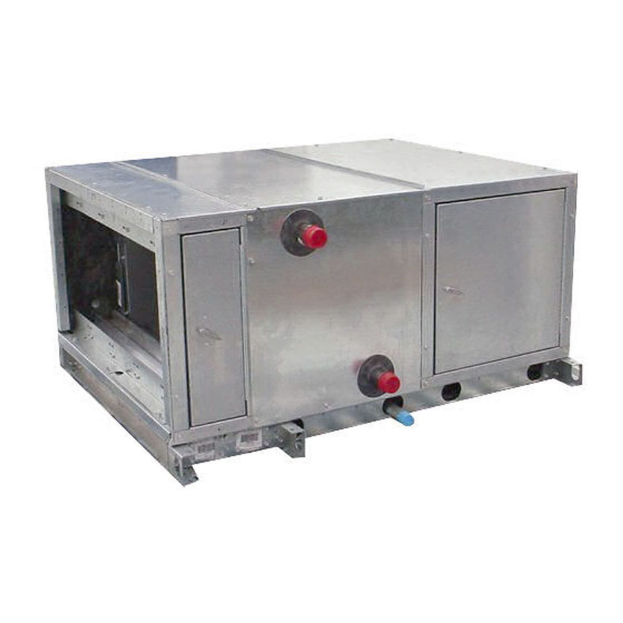
Page 2: Introduction
INTRODUCTION The 39L units are identified by Unit Identification — the 18-digit part number listed on the serial plate. The part number describes all component, coil, motor, drive, and control selections. See Fig. 1-3 for unit identification. Due to the complexity of the (18 position) 39L model number, use the “verify model number” function in the AHUBuilder®... -
Page 4: Preinstallation
PREINSTALLATION 1. Check items received against packing list. Notify Carrier of any discrepancy. 2. Refer to Fig. 4 for service area requirements. 3. To transfer unit from truck to storage site, refer to rigging details in Fig. 5 and section on unit rigging for proper handling. - Page 5 NOTE: Dimensions in ( ) are in mm. DIMENSIONS (ft-in.) SIZE 39LA 1- 7 1-11 2- 3 2- 3 2- 3 2-11 3- 3 3- 3 2- 3 SIZE 39LB 39LC 2- 3 1162 2- 3 1262 2- 3 1462...
- Page 6 UNIT SIZE UNIT WEIGHTS (lb)* 39LA 39LB 39LC 39LD 39LF 39LG 39LH COMPONENT WEIGHTS (lb) Mixing Box Section Filter Mixing Box Angle Filter Section Flat Filter Section Access Section Preheat (Water) Section Preheat (Electric) Section TYPICAL DRY COIL WEIGHTS (lb) Large Face Area Cooling Coils, -in.
- Page 7 NOTE: Lift in one piece. Use slings and spreader bars at each lifting bracket. Fig. 5 — Unit Rigging Details DRAIN NIPPLE TRAP CONDITION WHEN FAN STARTS COOLING COIL DRAIN PAN FAN RUNNING AND CONDENSATE DRAINING Fig. 7 — Condensate Drain Fig.
-
Page 8: Installation
INSTALLATION Mixing Box DAMPER ACTUATORS — The 39L mixing boxes are sup- plied with low leak dampers and blade and edge seals. Damper operating torques are shown in Table 2. The actuator and mounting brackets are field supplied and may be mounted inside or outside the unit. A typical inside mounting bracket is shown in Fig. - Page 9 ACCESSORY ACTUATOR VOLTAGE PACKAGE PART NO. (50/60 Hz) 33AMACTDMP133 HF27BJ035* 33AMACTGV-133 HF27BJ033 33AMACTGV-266 HF27BJ034 *Actuator is spring-return type. NOTES: 1. All actuators are direct coupled type, designed to be directly mounted into jackshaft assembly. 2. All actuators are equipped with a plenum rated cable, factory- terminated to the actuator.
-
Page 10: Inlet Guide Vane Actuators
Inlet Guide Vane (IGV) Actuators — board positions the unit IGVs in order to maintain the duct stat- ic pressure, as measured by the static pressure transducer, at the required set point. The IGV actuator is electrically connected to the control board and receives a signal whenever the guide vane position needs to be adjusted. -
Page 11: Install Fan Motor
Install Sheaves on Motor and Fan Shafts — Factory-supplied drives are prealigned and tensioned, however, Carrier recommends that you check the belt tension and align- ment before starting the unit. Always check the drive align- ment after adjusting belt tension. -
Page 12: Install V-Belts
When field installing or replacing sheaves, install sheaves on fan shaft and motor shaft for minimum overhang. (See Fig. 13.) Use care when mounting sheave on fan shaft; too much force may damage bearing. Remove rust-preventative coating or oil from shaft. Make sure shaft is clean and free of burrs. -
Page 13: Replacement Parts
Fig. 14 — Sheave Alignment 6. To determine correct belt tension, use the deflection formula given below and the tension data from Fig. 15 as follows: EXAMPLE: Given Belt Span 16 in. Belt Cross-Section A, Super Belt Small Sheave PD 5 in. -
Page 14: Water And Steam Piping Recommendations
When tightening coil connections, use a backup wrench on the nozzles. Piping practices are outlined in the Carrier System Design Manual, Part 3, Piping Design. See Tables 4-6 for circuiting data. WATER COILS — Typically, coils are piped by connecting the supply at the bottom and the return at the top. - Page 15 NOTE: IDT coils must be installed with the tubes draining toward the header end of the coil. Carrier's IDT steam coils are pitched toward the header end as installed in the unit. 10. Ensure the AHU (air-handling unit) is installed level to maintain the inherent slope.
- Page 16 NOTES: 1. A bypass is necessary around trap and valves when continu- ous operation is necessary. 2. Bypass to be the same size as trap orifice but never less than inch. Fig. 19 — Dripping Steam Supply to Condensate Return NOTES: 1.
-
Page 17: Refrigerant Piping, Direct Expansion
Q — Quarter Circuit Table 4 — Hot Water Coil Circuiting Data No. of Circuits NOTE: All hot water coils have 1 Table 5 — Chilled Water Coil Circuiting Data LARGE FACE AREA (39LA, 39LD) UNIT SIZE Face Area (sq ft) 5.90 7.90... - Page 18 Table 5 — Chilled Water Coil Circuiting Data (cont) COIL CIRCUITING TYPE 2.72 Connection Circuits Size 4-ROW — 6-ROW — 8-ROW* — SMALL FACE AREA (39LB, 39LC, 39LF) COIL CIRCUITING TYPE 12.12 Connection Circuits Size — 4-ROW — 6-ROW 8-ROW* LEGEND D —...
- Page 19 Refer to Carrier System Design Manual, Part 3, and size re- maining suction line to compressor for a pressure drop equiva- lent to 2.0 F. This will provide a total suction line header pres- sure drop equivalent to approximately 2.5 F.
- Page 20 *May be field manifolded for either face split or row split. †Where each TXV has the same number of circuits, that number is shown once. When coil has an uneven number of circuits per TXV, both values are shown. LARGE FACE AREA (39LA, 39LD) Half Full Half...
- Page 21 Table 7 — Direct Expansion Coil Circuiting Data (cont) UNIT SIZE CIRCUITING TYPE CFM AT 550 FPM FACE AREA (sq ft) TUBE FACE TUBE LENGTH (in.) NUMBER OF CIRCUITS NUMBER OF TXVs NUMBER OF CIRCUITS/TXV† SUCTION CONNECTIONS (in. OD) DISTRIBUTOR CONNECTIONS (in.
- Page 22 Table 8 — Distributor Part Numbers PART NO. CONNECTION OD (in.) TUBES Sporlan Carrier 1112-2- EA07NC261 1112-3- EA07FC027 1112-4- EA07NC262 0.88 1112-5- EA07NC263 1112-6- EA07NC264 1113-7- EA07HC207 1113-8- EA07HC208 1115-8- EA07KC240 1115-9- EA07KC241 1.12 1115-10- EA07KC242 1116-11- EA07HC011 1117-11- EA07LC510...
- Page 23 UNLOADING CONSIDERATIONS — Direct expansion coils can have two intertwined refrigerant circuits. In addition, quar- ter, half, full and double circuiting configurations are offered to allow optimum system performance and oil return at full and part-load operation. Circuiting selection should result in a circuit loading of 0.8 to 2.0 tons per circuit at design load.
- Page 24 TXV — Thermostatic Expansion Valve Fig. 29 — Face Split Coil Manifolding (Typical) TXV — Thermostatic Expansion Valve Fig. 30 — Row Split Coil Manifolding (Typical)
-
Page 25: Electric Heaters
Electric heaters may be factory in- Electric Heaters — stalled or drop shipped to the jobsite and field installed. The heater can only be installed in the preheat-electric section. To install electric heater, refer to Fig. 31 and proceed as follows: 1. - Page 26 NOTE: All wiring must be copper and must conform to the NEC (National Electrical Code). Fig. 32 — Typical Electric Heater Wiring Schematic...
- Page 27 NOMINAL UNIT HEATER NO. OF HEATER COIL FACE SIZE AREA CONTROL COIL VELOCITY (sq ft) STEPS* (fpm) 17.2 19.9 29.8 39.9 43.2 39.9 47.3 51.8 59.8 19.9 29.8 39.9 51.8 19.9 29.8 39.9 10.0 51.8 19.9 25.8 11.74 51.8 19.9 25.8 14.21 51.8...
-
Page 28: Discharge Modification
Table 11 — Field Wiring for Incoming Conductors Sized for 125% of Heater Load LOAD AMPS* WIRE SIZE WIRE SIZE (AWG or kcmil) (AWG or kcmil) Copper LEGEND AWG — American Wire Gage kcmil — Thousand Circular Mils *Values are based on Table 310-16 of the NEC (National Electrical Code) for 75 C insulated copper wire. -
Page 29: Start-Up
Fig. 34 — Fan Discharge Positions, Fans with IGVs START-UP Make a walkway inside unit components to Check List — protect insulation. Remove all construction debris from unit interior. Remove walkway before starting unit. FILTERS — Install unit filters in all filter sections. FANS 1. -
Page 30: Service
6. Check fan speed with a strobe-type tachometer or use the following formula: Obtain the motor rpm from the fan motor nameplate and read sheave pitch diameters marked on the fan and motor pulleys, or estimate the pitch diame- ters by using the pulley outside diameters. Then: Motor Rpm x Motor Sheave Pitch Diameter (in.) -
Page 31: Field-Installed Coils
5. Allow coil to stand for a few minutes; repeat step 4 until coil is dry. Field-Installed Coils (39LA,LD Only) When a 39LA or 39LD unit is ordered without the coil, the fol- lowing loose parts are shipped: (see Fig. 37) • bottom coil baffle •... - Page 32 5 — Piping 6 — Right Side Panels 7 — Right Support Panel Fig. 38 — Horizontal Unit Slant Coil Removal (39LA Units — Sizes 03-21) VERTICAL UNIT SLANT COIL REMOVAL (39LD Units) NOTE: Item numbers are in Fig. 39.
- Page 33 1. Refer to Fig. 4 for service area requirements. 2. Disconnect piping (Item 5). 3. Horizontal Unit, 39LA — On top panel (Item 3) remove screws located directly above side panels (Items 2 and 6). Top panels may be removed from unit to provide more workspace, but it is not required.
- Page 34 3 — Top Panels 4 — Baffle Angle Screws 5 — Piping Fig. 40 — Horizontal or Vertical Unit — Dual Coil Removal (39LA,LD Units, Sizes 25) HORIZONTAL OR VERTICAL UNIT — VERTICAL COIL REMOVAL (39LB,LC,LF,LH Units) — Item numbers are in Fig.
-
Page 35: Changing Coil Hand
1 — Accessory Side Panel 2 — Left Side Panel 3 — Inside Baffles 4 — Top Panels Fig. 41 — Horizontal or Vertical Unit — Vertical Coil Removal (39LB,LC,LF,LH Units) Changing Coil Hand NOTE: Electric heat coil hand cannot be changed. NOTE: The coil cover panel is not part of the coil. -
Page 36: Filters
There are additional precautions and control strategies, as found in various catalogues and in the ASHRAE Fundamentals Handbook and in the Carrier System Design Guide — Piping Section, when the entering-air temperature to the coil falls be- low 35 F. These conditions occur when IDT coils are used for pre-heat and/or face and bypass applications. - Page 37 39L UNIT SIZE Angle Filter Section 2…16x25 Filter Qty…Size (in.) Nominal Face Area (sq ft) 5.56 Filter Mixing Box Section 2…16x25 Filter Qty…Size (in.) Nominal Face Area (sq ft) 5.56 Flat Filter Section Filter Qty…Size (in.)* 2…16x16 Nominal Face Area (sq ft) 3.56 *Only 2-in.
-
Page 38: Fan And Shaft Removal
11. Field balancing of shaft and wheel is recommended. IMPORTANT: Replacement shafts must have a diam- eter tolerance at bearing mount of Carrier-specified parts are recommended. Lubrication MOTORS — Lubricate in accordance with nameplate at- tached to motor or with manufacturer’s recommendations included with motor. -
Page 39: Metric Conversion Chart
METRIC CONVERSION CHART... - Page 40 Copyright 2004 Carrier Corporation Manufacturer reserves the right to discontinue, or change at any time, specifications or designs without notice and without incurring obligations. Catalog No. 533-932 Printed in U.S.A. Form 39L-6SI Pg 40 1110 2-04 Replaces: 39L-5SI...