Carrier GEMINI 38APS025-065 Installation Instructions Manual
Air-cooled condensing units with puron refrigerant
Hide thumbs
Also See for GEMINI 38APS025-065:
- Product data (106 pages) ,
- Installation instructions manual (41 pages) ,
- Installation instructions (4 pages)
Table of Contents
Advertisement
Quick Links
A Legacy of Training
Willis H. Carrier began training members of
the heating, ventilation, air conditioning and
refrigeration industry in 1905. Carrier continues
to promote technical expertise in the industry
with the expansion of its sustainable solutions
curriculum and has recently been named a U.S.
Green Building Council Education Provider (USGBC EP).
To earn this status, Carrier's course materials were reviewed
by a panel of USBGC peers and deemed to provide the high
level of quality required for training Leadership in Energy and
Environmental Design (LEED
) professionals. The courses and
®
workshops supporting LEED-Accredited Professional and Green
Associates credential maintenance are administered through
Carrier University.
1-800-CARRIER www.carrier.com
© Carrier Corporation 2012
Cat. no. 04-811-50023
Manufacturer reserves the right to discontinue, or change at any time,
specifications or designs, without notice and without incurring obligations.
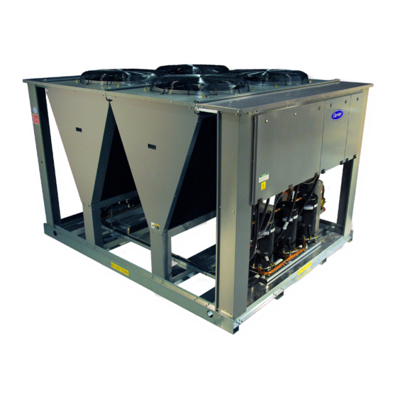
Gemini Select 38AP Commercial Condensing Units
• 25 to 130 Tons
• Digital compressor technology
• HFC Puron
refrigerant (R-410A)
®
• Reduced operating costs
• Quiet operation
• Reliable operation
• Freeze protection operating down to -20
F
o
• ASHRAE 90.1 compliant
• ETL listed
• Easy to start and operate
The Future of the World Depends on Our Ability...
to Sustain it.
As the world's leader in high technology
heating, air-conditioning and refrigeration
solutions, we believe that market leadership
requires environmental leadership. Carrier
sets industry standards for environmentally
sound business practices and a commitment
to sustainability across its products, services and operations.
We demonstrate this commitment by creating environmentally
responsible solutions that consume less energy and incorporate
innovations that improve the world – indoors and out.
Gemini
Select 38AP
®
Commercial Condensing Units
®
Advertisement
Chapters
Table of Contents
Troubleshooting

Related Manuals for Carrier GEMINI 38APS025-065


Summary of Contents for Carrier GEMINI 38APS025-065
- Page 1 Green Building Council Education Provider (USGBC EP). to sustainability across its products, services and operations. To earn this status, Carrier’s course materials were reviewed We demonstrate this commitment by creating environmentally by a panel of USBGC peers and deemed to provide the high...
- Page 2 15.1 Along with cost efficiency in purchase and installation, Gemini Select Leave it to Carrier to design condensing units in ways you’ll notice at commercial condensing units are also more affordable to operate. the initial purchase, through installation, and for years afterward. Our Length (in.)
-
Page 3: Table Of Contents
GEMINI™ SELECT 38APS025-065, 38APD025-130 ® Air-Cooled Condensing Units with PURON Refrigerant (R-410A) 50/60 Hz Installation Instructions CONTENTS CAUTION Page SAFETY CONSIDERATIONS ..... . 1 Puron refrigerant (R-410A) systems operate at higher pres- INSTALLATION . -
Page 4: Domestic Units
DOMESTIC UNITS Standard 38AP unit packaging con- 4 x 24 in. perimeter support ASTM C channels between unit sists of coil protection only. Skids are not provided. If overhead and the isolators are recommended with a minimum of 4 chan- rigging is not available at the jobsite, place the unit on a skid or nels per unit. - Page 5 Table 1 — 38AP025-050 Unit Physical Data — English 38AP UNIT SIZE NOMINAL CAPACITY, 50/60 Hz (tons) 21/25 23/27 25/30 33/40 42/50 CIRCUIT Dual Single Dual Single Dual Single Dual Single Dual Single OPERATING WEIGHTS (lb) Standard 1095 1077 1258 1240 1264 1246...
- Page 6 Table 2 — 38AP060-130 Unit Physical Data — English 38AP UNIT SIZE NOMINAL CAPACITY, 50/60 Hz (tons) 50/60 54/65 58/70 67/80 75/90 83/100 96/115 108/130 CIRCUIT Dual Single Dual Dual Dual Dual Dual Dual OPERATING WEIGHTS (lb) Standard 2227 2561 2450 2610 2835...
- Page 7 Table 3 — 38AP025-050 Unit Physical Data — SI 38AP UNIT SIZES NOMINAL CAPACITY 50/60 Hz (kW) 73/88 79/95 88/105 117/141 146/176 CIRCUIT Dual Single Dual Single Dual Single Dual Single Dual Single OPERATING WEIGHTS (kg) Standard With Low Sound Option REFRIGERANT CHARGE (kg) Total* 11/—...
- Page 8 Table 4 — 38AP060-130 Unit Physical Data — SI 38AP UNIT SIZES NOMINAL CAPACITY 50/60 Hz (kW) 176/211 190/228 205/246 234/281 264/316 293/351 337/404 381/457 CIRCUIT Dual Single Dual Dual Dual Dual Dual Dual OPERATING WEIGHTS (kg) Standard 1010 1162 1111 1184 1286...
- Page 9 38APS Unit (lb) 38APS Unit (kg) 38APS OPERATIONAL CORNER WEIGHT 38APS OPERATIONAL CORNER WEIGHT TOTAL TOTAL UNIT UNIT WEIGHT WEIGHT SIZE SIZE 1089 1255 1261 1998 2007 2594 1177 38APD Unit (lb) 38APD Unit (kg) 38APD OPERATIONAL CORNER WEIGHT 38APD OPERATIONAL CORNER WEIGHT TOTAL TOTAL...
- Page 10 a38-7115 2633 1194 2733 1240 SIZES 025 TO 060 SIZES 065 TO 130 a38-7202 Fig. 3 — Rigging Labels a38-7130 LEGEND 4 x 24 in. ASTM “C” ASTM — American Society for Testing and Materials CHANNEL Fig. 4 — Perimeter Support Channel...
- Page 11 a38-7101...
- Page 12 a38-7224...
- Page 14 a38-7104...
- Page 16 Outdoor Fan Layout OFM1 OFM1 OFM3 OFM1 OFM1 OFM5 OFM3 OFM3 OFM2 OFM2 OFM2 OFM6 OFM4 OFM2 Top View Top View Top View Top View Sizes 025-030 Sizes 040-050 Sizes 060-070 Size 080 OFM3 OFM7 OFM3 OFM5 OFM1 OFM3 OFM5 OFM7 OFM1 OFM1...
- Page 17 40RU a38-7237 LEGEND NOTES: 1. All piping must follow standard refrigerant piping techniques. Refer to Carrier System LLSV — Liquid Line Solenoid Valve Design Manual for details. NEC — National Electrical Code 2. All wiring must comply with the applicable local and national codes.
- Page 18 NOTES: LEGEND 1. All piping must follow standard refrigerant piping techniques. Refer to Carrier System LLSV — Liquid Line Solenoid Valve Design Manual for details. NEC — National Electrical Code 2. All wiring must comply with the applicable local and national codes.
- Page 19 AHRI Standard 710. 2. All pipe sizes are OD inches. Equivalent sizes in millimeters follow: 12.7 15.9 22.2 28.6 3. Thermostatic expansion valve (TXV) is provided with all 40RU fan coil units. Contact your Carrier representative for appropriate TXV size.
-
Page 20: Step 3 - Make Refrigerant Piping
SIZE REFRIGERANT LINES Consider the length of pip- Step 3 — Make Refrigerant Piping ing required between the condensing unit and indoor unit Connections (evaporator), the amount of liquid lift, and compressor oil re- turn. Suction and liquid lines should be sized in accordance CAUTION with Table 6. - Page 21 Table 6 — Refrigerant Piping Requirements 38APS025-050 Single-Circuit Units (60 Hz) TOTAL LINEAR LENGTH OF INTERCONNECTING PIPE, ft (m) CONN 0-25 25-50 50-75 75-100 100-125 125-150 150-175 175-200 38APS UNIT SIZE (0-7.6) (7.6-15.2) (15.2-22.9) (22.9-30.5) (30.5-38.1) (38.1-45.7) (45.7-53.3) (53.3-61.0) (in.) 38APD025-100 Dual-Circuit Units (60 Hz) TOTAL LINEAR LENGTH OF INTERCONNECTING PIPE, ft (m) CONN...
- Page 22 Table 6 — Refrigerant Piping Requirements (cont) 38APS025-050 Single-Circuit Units (50 Hz) TOTAL LINEAR LENGTH OF INTERCONNECTING PIPE, ft (m) CONN 0-25 25-50 50-75 75-100 100-125 125-150 150-175 175-200 38APS UNIT SIZE (0-7.6) (7.6-15.2) (15.2-22.9) (22.9-30.5) (30.5-38.1) (38.1-45.7) (45.7-53.3) (53.3-61.0) (in.) 38APD025-100 Dual-Circuit Units (50 Hz) TOTAL LINEAR LENGTH OF INTERCONNECTING PIPE, ft (m)
- Page 23 Table 6 — Refrigerant Piping Requirements (cont) 38APS025-65 Single-Circuit Units Double Suction Riser (60 Hz) TOTAL LINEAR LENGTH OF INTERCONNECTING PIPE, ft (m) CONN 0-25 25-50 50-75 75-100 100-125 125-150 150-175 175-200 38APS UNIT SIZE (0-7.6) (7.6-15.2) (15.2-22.9) (22.9-30.5) (30.5-38.1) (38.1-45.7) (45.7-53.3) (53.3-61.0)
- Page 24 Table 6 — Refrigerant Piping Requirements (cont) 38APS025-65 Single-Circuit Units Double Suction Riser (50 Hz) TOTAL LINEAR LENGTH OF INTERCONNECTING PIPE, ft (m) CONN 0-25 25-50 50-75 75-100 100-125 125-150 150-175 175-200 38APS UNIT SIZE (0-7.6) (7.6-15.2) (15.2-22.9) (22.9-30.5) (30.5-38.1) (38.1-45.7) (45.7-53.3) (53.3-61.0)
-
Page 25: Liquid Line Solenoid Valve
LIQUID LINE SOLENOID VALVE Field-supplied HOT GAS BYPASS Hot gas bypass is not recommended. liquid line solenoid valve(s) must be installed at the evaporator If hot gas bypass is used, it should be introduced before the if coil surface area is exceeded per Tables 7A and 7B. Install evaporator. - Page 26 † LLSV † LLSV LEGEND LLSV — Liquid Line Solenoid Valve — Thermostatic Expansion Valve a38-7233 *Field-supplied. †Field-supplied when required. See Tables 7A and 7B. Fig. 14 — Required Location of Solenoid Valves and Recommended Filter Drier and Sight Glass Locations for 38APD025-130 Dual-Circuit Units a38-7118 SECTION 1 LIQUID...
- Page 27 SECTION SECTION SECTION SECTION LEGEND TXV — Thermostatic Expansion Valve a38-7234 TYP — Typical NOTE: For units with single condensate pan, lower coil section is first on, last off. Fig. 16 — Typical Piping Connections for Face Split Coils for 38APD025-130 Dual-Circuit SECTION SECTION SECTION...
- Page 28 Table 7A — Requirements for Installation of Liquid Line Solenoid Valve MAXIMUM ALLOWABLE EVAPORATOR SURFACE AREA 38AP UNIT WITHOUT LIQUID LINE SOLENOID VALVE (sq ft) CIRCUIT SIZE 4-Row, in. Tube 6-Row, in. Tube 8-Row, in. Tube 3-Row, in. Tube 4-Row, in.
- Page 29 Table 7B — Requirements for Installation of Liquid Line Solenoid Valve (SI) MAXIMUM ALLOWABLE EVAPORATOR SURFACE AREA 38AP UNIT WITHOUT LIQUID LINE SOLENOID VALVE (sq m) CIRCUIT SIZE 4-Row, in. Tube 6-Row, in. Tube 8-Row, in. Tube 3-Row, in. Tube 4-Row, in.
-
Page 30: Step 4 - Make Electrical Connections
Class 1 AC service wiring. Do abuse and may adversely affect Carrier warranty. not abrade, cut, or nick the outer jacket of the cable. Do not pull or draw cable with a force that may harm the physical or elec- trical properties. - Page 31 a38-7122 LEGEND c. Incoming wire size range for non-fused disconnect with MCA up to 100 amps is 14 AWG to 1/0. EQUIP GND — Equipment Ground d. Incoming wire size range for non-fused disconnect with MCA from — National Electrical Code 100.1 amps to 200 amps is 6 AWG to 350 kcmil.
- Page 32 TERMINAL STRIP REMOTE ON/OFF COOL 2 a38-7235 COOL 1 *LLSV-A2 for 38APS025-065 single circuit units (optional). Fig. 21— Constant Volume Application Wiring Diagram 2-Stage Thermostat Control — 38AP025-030 Units without Digital Scroll Option TERMINAL STRIP REMOTE ON/OFF COOL 2 a38-7236 COOL 1 *See Fig.
- Page 33 TERMINAL STRIP REMOTE ON/OFF *See Fig. 20 for SAT and MAT/RAT location. †LLSV-A2 for 38APS025-065 single circuit units (optional). Fig. 23 — Constant Volume Application Wiring Diagram Space Temperature Sensor Control — 38AP025-130 Units TERMINAL STRIP REMOTE ON/OFF a38-7128 *See Fig. 20 for SAT and MAT/RAT location. †LLSV-A2 for 38APS025-065 single circuit units (optional).
- Page 34 TERMINAL STRIP a38-7129 Fig. 25 — Optional Energy Management Module Wiring Legend and Notes for Fig. 21-27 LEGEND 3. Wiring for main field supply must be rated 75 C. Use copper conductors only. ALM R — Alarm Relay (24-v), 5-va Maximum 4.
- Page 35 38AP UNIT WITH NO EMM LVT TERMINAL STRIP Fig. 26 — Typical Control Wiring — 38AP/40RU Units with Two-Stage Thermostat and without EMM Board 38AP UNIT WITH NO EMM LVT TERMINAL STRIP FIELD-SUPPLIED 24 VAC TRANSFORMER (40 VA) (DRY FIELD-SUPPLIED CONTACT) RELAYS (DRY...
- Page 36 Table 8 — 38APS Standard Condenser Fan Electrical Data SUPPLY COMPRESSOR CONDENSER FAN 38APS UNIT VOLTAGE V-Ph-Hz MOCP SIZE FUSE Total Qty 208/230-3-60 48.1 121.4 306.3 380-3-60 23.7 61.1 176.5 460-3-60 18.6 48.5 150.2 575-3-60 14.7 38.3 119.9 380/415-3-50 18.6 48.5 143.2 208/230-3-60...
- Page 37 Table 10 — 38APD Standard Condenser Fan Electrical Data COMPRESSOR CONDENSER FAN SUPPLY 38APD VOLTAGE V-Ph-Hz CIRCUIT A CIRCUIT B MOCP UNIT SIZE Total Qty FUSE 208/230-3-60 48.1 48.1 121.4 306.3 380-3-60 23.7 23.7 61.1 176.5 460-3-60 18.6 18.6 48.5 150.2 575-3-60 14.7...
- Page 38 Table 11 — 38APD Low Sound Condenser Fan Electrical Data COMPRESSOR CONDENSER FAN SUPPLY 38APD VOLTAGE V-Ph-Hz CIRCUIT A CIRCUIT B MOCP UNIT SIZE Total Qty FUSE 208/230-3-60 48.1 48.1 120.2 305.1 380-3-60 23.7 23.7 61.1 176.5 460-3-60 18.6 18.6 47.7 149.4 575-3-60...
-
Page 39: Step 5 - Install Accessories
Table 12 — Unit Incoming Power Options UNIT INCOMING POWER OPTION Standard Terminal Standard and High SCCR High SCCR Terminal Block Option MOCP VALUE Block Option Disconnect Option High SCCR Max Wire Size Wire Size Wire Size Wire Size Wire Size Fuse Type Wire Size 100 A or less... - Page 42 Copyright 2011 Carrier Corporation Manufacturer reserves the right to discontinue, or change at any time, specifications or designs without notice and without incurring obligations. Catalog No. 04-53380012-01 Printed in U.S.A. Form 38AP-7SI Pg 40 7-11 Replaces: 38AP-6SI...
-
Page 43: Safety Considerations
Control Module Communication....19 LOSS OF CCN COMMUNICATIONS (CCN) Interface..20 Carrier Comfort Network ® TROUBLESHOOTING OPERATING DATA......20-33 REPLACING DEFECTIVE MODULES Sensors . -
Page 44: General
R-22 systems. Do not use R-22 ser- vice equipment or components on Puron refrigerant equip- names in text. ment. If service equipment is not rated for Puron The CCN (Carrier Comfort Network ® ) point names are also refrigerant, equipment damage or personal injury may referenced in the local display tables for users configuring the result. - Page 45 LEGEND — Auxiliary — Contactor — Circuit Breaker CCHR — Crankcase Heater Relay — Current Sensor Board — Energy Management Module EQUIP GND — Equipment Ground — Fuse Block — Fan Contactor — Local Operating Network — Main Base Board —...
- Page 46 LEGEND — Auxiliary — Contactor — Circuit Breaker — Crankcase Heater Relay — Current Sensor Board — Energy Management Module EQUIP GND — Equipment Ground — Fan Contactor — Fan Circuit Breaker — Local Operating Network — Main Base Board —...
- Page 47 LEGEND — Auxiliary — Contactor — Circuit Breaker — Crankcase Heater Relay — Current Sensor Board — Compressor Expansion Board — Energy Management Module EQUIP GND — Equipment Ground — Fan Contactor — Fan Circuit Breaker — Local Operating Network —...
- Page 48 Fig. 4 — Power Wiring Schematic — 38APS,APD025-030...
- Page 49 Fig. 5 — Power Wiring Schematic — 38APS040,050...
- Page 50 Fig. 6 — Power Wiring Schematic — 38APD040-060...
- Page 51 Fig. 7 — Power Wiring Schematic — 38APD070-100...
- Page 52 Fig. 8 — Control Wiring Schematic — 38APS025-050...
- Page 53 Fig. 9 — Control Wiring Schematic — 38APD025-060...
- Page 54 Fig. 10 — Control Wiring Schematic — 38APD070-100...
- Page 55 Legend and Notes for Fig. 4-10 LEGEND NOTES: 1. Factory wiring is in accordance with UL (Underwriters Labora- ACCSY — Accessory tories) 1995 standards. Any field modifications or additions — Alarm must be in compliance with all applicable codes. AMPS —...
- Page 56 a38-7122 LEGEND b. Incoming wire size range for terminal block with MCA from 175.1 amps to 420 amps is 2 AWG to 600 kcmil. EQUIP GND — Equipment Ground c. Incoming wire size range for non-fused disconnect with MCA up to —...
- Page 57 TERMINAL STRIP REMOTE ON/OFF COOL 2 COOL 1 a38-7125 *Not required for single circuit units. Fig. 13 — Constant Volume Application Wiring Diagram 2-Stage Thermostat Control, Sizes 025-030 — without Digital Scroll Option TERMINAL STRIP REMOTE ON/OFF COOL2 COOL 1 a38-7126 *See Fig.
- Page 58 TERMINAL STRIP REMOTE ON/OFF a38-7128 *See Fig. 12 for MAT/RAT and SAT location. †Not required for single circuit units. Fig. 16 — Variable Air Volume Application Wiring Diagram, Sizes 025-100 TERMINAL STRIP a38-7129 Fig. 17 — Optional Energy Management Module Wiring Legend and Notes for Fig.
-
Page 59: Display Module Usage
Display Module Usage SCROLLING MARQUEE DISPLAY This device is the keypad interface used for accessing unit information, reading sensor values, and testing the unit. See Fig. 18. The scrolling marquee display is a 4-key, 4-character, 16-segment LED (light-emitting diode) display. Eleven mode LEDs are located on the display as well as an Alarm Status LED. -
Page 60: Main Base Board (Mbb)
Adjusting the Contrast The contrast of the display can be view screen. Pressing the up and down arrow keys simultane- adjusted to suit ambient conditions. To adjust the contrast of ously allows the user to adjust the display brightness. Use the the Navigator module, press the ESCAPE key until the dis-... -
Page 61: Compressor Expansion Module (Cxb)
The MBB has one yellow LED. The sition and a field-installed dry contact can be used to start the Carrier Comfort Network (CCN) LED will blink during times unit. The contacts must be capable of handling a 24 vac, 50 mA of network communication. -
Page 62: Carrier Comfort Network (Ccn) Interface
Fig. 21 — Scrolling Marquee, Enable/Off/Remote Contact Switch, and Emergency On/Off Switch Locations 4. The RJ14 CCN connector on LVT can also be used, but is ® Carrier Comfort Network (CCN) Interface — only intended for temporary connection (for example, a The 38AP units can be connected to the CCN if desired. -
Page 63: Supply Air Temperature (Sat) Accessory
3.90 3.00 RED(+) .175 DIA WHT(GND) CCN COM x .600 BLK(-) BRN (GND) SENSOR WIRING BLU (SPT) FOAM GASKET .40'' O.D. .250 ±.01 Dia 5.5 ±.5 NOTE: All dimensions PLENUM RATED CABLE Fig. 23 — Space Temperature Sensor shown in inches. 114'' ±6 Typical Wiring (33ZCT55SPT) Fig. - Page 64 Units on the CCN can be monitored from the space using the RJ11 connector provided with the space sensor, if desired. To wire the RJ11 connector into the CCN (Fig. 26): SENSOR IMPORTANT: The cable selected for the RJ11 connector wiring MUST be identical to the CCN communication bus wire used for the entire network.
-
Page 65: Fan Status Input
See VAV Supply Air Temperature Reset and Demand Limit A proof-of-fan operation is recom- Fan Status Input — sections on pages 29 and 31 for further details. mended and needs to be field installed in the indoor unit. Sev- eral different types of switches can be utilized, such as a differ- ential pressure switch located across the indoor fan or auxiliary CAUTION contacts on an indoor fan contactor. - Page 66 C.TYP = 3 (TSTAT-MULTI) configuration will force supply air depending on space temperature vs space the MBB to monitor the thermostat inputs to make a temperature set point. The control uses SPS.P, LC.ON, determination of mode. Unlike traditional 2-stage ther- HC.ON, and LC.OF to determine the leaving set point.
- Page 67 the return temperature, space, or outdoor-air temperature reset The capacity control algorithm runs every 30 seconds. The features. It can also be reset from an external 4 to 20 mA signal algorithm attempts to maintain the control point at the desired (requires energy management module factory-installed option set point.
-
Page 68: Head Pressure Control
MINUTES LEFT FOR START This value is displayed close to the set point (within an adjustable deadband) and mov- only in the network display tables (using Service Tool, ing toward the set point. ComfortVIEW or ComfortWORKS software) and ® Ramp Loading The ramp loading control (Configuration represents the amount of time to elapse before the unit will start ... - Page 69 Outdoor Fan Layout – Top View OFM1 OFM1 OFM1 OFM3 OFM3 OFM2 OFM2 OFM2 OFM4 Sizes 025-030 Sizes 040, 050 Sizes 060, 070 OFM1 OFM3 OFM5 OFM1 OFM5 OFM3 OFM2 OFM6 OFM2 OFM4 OFM6 Size 080 Sizes 090, 100 Compressor Layout Dual Circuit – Top View Sizes 025-030 Sizes 040-060 Sizes 070, 080...
-
Page 70: Service Test
Occupied mode. Over- for local schedule. ride can be implemented with unit under Local (Enable) or CCN (Carrier Comfort Network ® ) control. Override expires af- The schedule number can be set anywhere from 65 to 99 ter each use. -
Page 71: Set Point Adjustment
CHIL_S_S variable is 'Stop.' Similarly, the control mode will be set to the temperature difference where the maximum reset be 6 when the CHIL_S_S variable is 'Start.' should occur. The variable RM.DG should be set to the maximum amount of reset desired. To verify that reset is func- Set Point Adjustment tioning correctly proceed to Run Status mode, sub-mode CV SET POINT ADJUSTMENT... - Page 72 Table 10 — 4 to 20 mA Reset KEYPAD ITEM SUB-MODE ITEM DISPLAY COMMENT ENTRY EXPANSION RSET 0 = no reset 1 = 4 to 20 mA Input COOLING RESET 2 = Outdoor Air Temp CRST ENTER TYPE 3 = Return Fluid 4 = Space Temperature 5.0 F Default: 0°...
-
Page 73: Demand Limit
from exceeding the capacity entered as Demand Limit Switch Demand Limit is a feature that allows Demand Limit — 2 set point. The demand limit stage that is set to the lowest the unit capacity to be limited during periods of peak energy demand takes priority if both demand limit inputs are closed. -
Page 74: Demand Limit (Ccn Loadshed Controlled)
50% CAPACITY AT 20 mA DM20 = 50 100% CAPACITY AT 4mA 75% CAPACITY AT 12 mA 50% CAPACITY AT 12 mA DM20 = 0 DEMAND LIMIT SIGNAL – 4 - 20 mA INPUT Fig. 33 — 4 to 20 mA Demand Limiting — Demand Limit Select (DMDC = 2) DEMAND LIMIT (CCN Loadshed Controlled) To con- compressor is always installed in the A1 compressor location. -
Page 75: Pre-Start-Up
CAUTION gized for at least 24 hours. See Add Oil section on page 47, for Carrier-approved oils. Crankcase heaters on all units are wired into the control cir- cuit, so they are always operable as long as the main power 5. -
Page 76: Adjust Refrigerant Charge
Table 15 — Preliminary Puron Refrigerant (R-410A) CAUTION Charge, lb (kg) 38AP UNIT SIZE CIRCUIT A CIRCUIT B Charging procedures for MCHX (microchannel heat 38APS025 24 (10.9) — exchanger) units require very accurate measurement tech- 38APD025 12 (5.6) 12 (5.6) niques. - Page 77 Circuit A or B Circuit A or B 50 SST 50 SST 40 SST 40 SST 30 SST 30 SST ADD CHARGE IF ABOVE CURVE ADD CHARGE IF ABOVE CURVE REDUCE CHARGE IF BELOW CURVE REDUCE CHARGE IF BELOW CURVE a38-7169 LIQUID PRESSURE AT LIQUID VALVE (PSIG) 1500...
- Page 78 Circuit A or B Circuit A or B 50 SST 50 SST 40 SST 40 SST 30 SST 30 SST ADD CHARGE IF ABOVE CURVE ADD CHARGE IF ABOVE CURVE REDUCE CHARGE IF BELOW CURVE a38-7171 LIQUID PRESSURE AT LIQUID VALVE (PSIG) 1500 4000 2000...
- Page 79 Circuit A or B Circuit A or B 50 SST 50 SST 40 SST 40 SST 30 SST 30 SST ADD CHARGE IF ABOVE CURVE ADD CHARGE IF ABOVE CURVE REDUCE CHARGE IF BELOW CURVE a38-7173 LIQUID PRESSURE AT LIQUID VALVE (PSIG) 1500 4000 2000...
- Page 80 Circuit A Circuit A 50 SST 50 SST 40 SST 40 SST 30 SST 30 SST ADD CHARGE IF ABOVE CURVE ADD CHARGE IF ABOVE CURVE REDUCE CHARGE IF BELOW CURVE LIQUID PRESSURE AT LIQUID VALVE (PSIG) a38-7175 1500 4000 2000 2500 3000...
- Page 81 Single Circuit Single Circuit 130.0 130.0 50 SST 50 SST 40 SST 40 SST 30 SST 30 SST 120.0 120.0 ADD CHARGE IF ABOVE CURVE ADD CHARGE IF ABOVE CURVE 110.0 110.0 100.0 100.0 90.0 90.0 REDUCE CHARGE IF BELOW CURVE REDUCE CHARGE IF BELOW CURVE 80.0 70.0...
- Page 82 Circuit B Circuit B 50 SST 50 SST 40 SST 40 SST 30 SST 30 SST ADD CHARGE IF ABOVE CURVE ADD CHARGE IF ABOVE CURVE REDUCE CHARGE IF BELOW CURVE LIQUID PRESSURE AT LIQUID VALVE (PSIG) a38-7179 1500 4000 2000 2500 3000...
- Page 83 Circuit A Circuit A 130.0 130.0 50 SST 50 SST 40 SST 40 SST 120.0 120.0 30 SST 30 SST ADD CHARGE IF ABOVE CURVE ADD CHARGE IF ABOVE CURVE 110.0 110.0 100.0 100.0 90.0 90.0 REDUCE CHARGE IF BELOW CURVE REDUCE CHARGE IF BELOW CURVE 80.0 70.0...
- Page 84 Circuit A Circuit A 50 SST 50 SST 40 SST 40 SST 30 SST 30 SST ADD CHARGE IF ABOVE CURVE ADD CHARGE IF ABOVE CURVE REDUCE CHARGE IF BELOW CURVE a38-7183 LIQUID PRESSURE AT LIQUID VALVE (PSIG) 1500 4000 2000 2500 3000...
- Page 85 Circuit A Circuit A 50 SST 50 SST 40 SST 40 SST 30 SST 30 SST ADD CHARGE IF ABOVE CURVE ADD CHARGE IF ABOVE CURVE REDUCE CHARGE IF BELOW CURVE a38-7185 LIQUID PRESSURE AT LIQUID VALVE (PSIG) 1500 4000 2000 2500 3000...
- Page 86 Circuit A Circuit A 50 SST 50 SST 40 SST 40 SST 30 SST 30 SST ADD CHARGE IF ABOVE CURVE ADD CHARGE IF ABOVE CURVE REDUCE CHARGE IF BELOW CURVE a38-7187 LIQUID PRESSURE AT LIQUID VALVE (PSIG) 1500 4000 2000 2500 3000...
- Page 87 Circuit A Circuit A 50 SST 50 SST 40 SST 40 SST 30 SST 30 SST ADD CHARGE IF ABOVE CURVE ADD CHARGE IF ABOVE CURVE REDUCE CHARGE IF BELOW CURVE LIQUID PRESSURE AT LIQUID VALVE (PSIG) a38-7189 1500 4000 2000 2500 3000...
- Page 88 a38-7117 † † LEGEND LLS — Liquid Line Solenoid TXV — Thermostatic Expansion Valve *Field-supplied. †Field-supplied when required. Must be controlled by 38AP unit control. Fig. 57 — Required Location of Solenoid Valves and Recommended Filter Drier and Sight Glass Locations for 38APD025-100 Dual-Circuit Units a38-7118 SECTION 1 LIQUID...
-
Page 89: Check Compressor Oil Level
Run all com- pressors for 20 minutes then shut off to check oil level. Repeat DTT A procedure until acceptable oil level is present. NOTE: Use only Carrier approved compressor oil. Approved OIL ADD sources are: LOCATION Totaline . -
Page 90: Operation
2. Fan status switch input should close. Note the unit will The maximum voltage deviation is the largest difference not start unless the fan status input is closed. between a voltage measurement across 2 legs and the average across all 3 legs. 3. -
Page 91: Service
For all units, if temperature reset is used, the unit controls to (SPT), supply air temperature (SAT) and return air temperature a higher leaving temperature as the building load reduces. If (RAT/EAT) thermistors. demand limit is used, the unit may temporarily be unable to SPACE TEMPERATURE THERMISTOR (SPT) This maintain the desired leaving-air temperature because of im-... - Page 92 Table 17 — 5K Thermistor Temperatures (°F) vs. Resistance/Voltage Drop VOLTAGE VOLTAGE VOLTAGE TEMP RESISTANCE TEMP RESISTANCE TEMP RESISTANCE DROP DROP DROP (Ohms) (Ohms) (Ohms) 1.982 7,686 0.511 1,190 –25 3.699 98,010 1.956 7,665 0.502 1,165 –24 3.689 94,707 1.930 7,468 0.494 1,141...
- Page 93 Table 18 — 5K Thermistor Temperatures (°C) vs. Resistance/Voltage Drop VOLTAGE VOLTAGE VOLTAGE TEMP RESISTANCE TEMP RESISTANCE TEMP RESISTANCE DROP DROP DROP (Ohms) (Ohms) (Ohms) 1.982 7,855 0.506 1,158 –32 3.705 100,260 1.935 7,499 0.490 1,118 –31 3.687 94,165 1.889 7,161 0.475 1,079...
- Page 94 Table 19 — 10K Thermistor Temperature (°F) vs. Resistance/Voltage Drop VOLTAGE VOLTAGE VOLTAGE TEMP RESISTANCE TEMP RESISTANCE TEMP RESISTANCE DROP DROP DROP (Ohms) (Ohms) (Ohms) –25 4.758 196,453 2.994 14,925 0.890 2,166 –24 4.750 189,692 2.963 14,549 0.876 2,124 –23 4.741 183,300 2.932...
- Page 95 Table 20 — 10K Thermistor Temperature (°C) vs. Resistance/Voltage Drop VOLTAGE VOLTAGE VOLTAGE TEMP RESISTANCE TEMP RESISTANCE TEMP RESISTANCE DROP DROP DROP (Ohms) (Ohms) (Ohms) –32 4.762 200,510 3.056 15,714 0.940 2,315 –31 4.748 188,340 3.000 15,000 0.913 2,235 –30 4.733 177,000 2.944...
-
Page 96: Pressure Transducers
The suction and discharge Pressure Transducers — transducers are different part numbers and can be distinguished by the color of the transducer body, suction (yellow) and dis- charge (red). Figures 59 and 60 shows typical location of pres- sure transducers on each circuit. No pressure transducer cali- bration is required. -
Page 97: Configuration
It is strongly recommended that the user NOT change any ule (EPM) chip to store the program parameters. This is an programming without consulting Carrier service personnel. EEPROM memory chip and is accessible from the front of the Unit damage may occur from improper programming. - Page 98 Mode DANGER LEGEND — Motormaster V Control TERMINAL BLOCK T1 T2 T3 DISPLAY BUTTONS Mode Fig. 63 — Motormaster ® V Mode Buttons and Mode Display Table 22 — Fault Codes FAULT CODE DESCRIPTION SOLUTION High Temperature Fault: Ambient temperature is too high; Cooling Check cooling fan operation fan has failed (if equipped).
- Page 99 MOTORMASTER V TERMINAL BLOCK 208/230, 460, 575 VOLT ONLY 208 VOLT ONLY LEGEND Configuration Table AUX — Auxiliary CONTROL INPUT — Fuse Block MODE NOMINAL VOLTAGE START JUMPER (PINS 25, 2) — Fan Relay — Motormaster 208/230/460/575* External control 4-20 mA TB1-TB2 OFM —...
- Page 100 MODE 7 MODE 8 Line Voltage: 01 = low line, 02 = high line Carrier Freq: 01 = 4 kHz, 02 = 6 kHz, 03=8 kHz Start-up mode: flying restart Stop mode: coast to stop Standard Speed source: 04=4-20 mA, 05=R22, 06=R134a...
-
Page 101: Troubleshooting
(all other modules) exactly match the settings of the than recommended. defective module. NOTE: Handle boards by mounting standoffs only to avoid electrostatic discharge. 4. Package the defective module in the carton of the new module for return to Carrier. -
Page 102: Microchannel Heat Exchanger (Mchx) Condenser Coil Maintenance And Cleaning
Every month: TROUBLESHOOTING Check condenser coils for debris, clean as necessary. Possi- Complete Unit Stoppage and Restart — Check moisture indicating sight glass for possible refrig- ble causes for unit stoppage and reset methods are shown be- erant loss and presence of moisture. low. -
Page 103: Alarms And Alerts
Low Saturated Suction Several conditions can lead to low saturated suction alarms. The controls have several override modes built in which will attempt to keep the unit from shutting down. Low airflow, low refrigerant charge and plugged filter driers are the main causes for this condition. To avoid permanent damage, do NOT repeatedly reset these alert and/or alarm conditions without identifying and correcting the cause(s). - Page 104 Wiring Error A wiring error might not allow the compres- control, the supply-air temperature must be updated every sor to start. 3 minutes. If it is not updated, then the alarm will be generated. Failure of this thermistor will shut down the entire unit. To check out alerts T051-T057: A061 (Return Air Thermistor Failure) If the unit is re-...
- Page 105 T114 (Circuit A Low Superheat) continues to rise to greater than 150 F (65.6 C), the alert will T115 (Circuit B Low Superheat) Alert codes 114 and 115 occur and the circuit's remaining compressor will shut down. occur when the superheat of a circuit is less than 5 F (2.8 C) for The cause of the alarm is usually an overcharged system, high 5 continuous minutes.
- Page 106 Digital compressor shut down. Automatic Thermistor Failure either open or shorted LEGEND ® — Carrier Comfort Network — Leaving Fluid Temperature — Current Sensor Board — Main Base Board — Compressor Expansion Module — Saturated Condensing Temperature — Discharge Temperature Thermistor —...
- Page 107 Both circuits are down due to alarms/alerts. Unit is unable to run. cleared that prevent the chiller from starting. LEGEND — Carrier Comfort Network ® — Leaving Fluid Temperature — Current Sensor Board — Main Base Board — Compressor Expansion Module —...
- Page 108 Compressor B3 shut down Automatic B3 Failure is a constant high value LEGEND ® — Carrier Comfort Network — Leaving Fluid Temperature — Current Sensor Board — Main Base Board — Compressor Expansion Module — Saturated Condensing Temperature — Discharge Temperature Thermistor —...
-
Page 109: Appendix A - Display Tables
APPENDIX A — DISPLAY TABLES Run Status Mode and Sub-Mode Directory SUB-MODE ITEM DISPLAY ITEM DESCRIPTION COMMENT VIEW xxx.x ºF Return Air Temperature xxx.x ºF Supply Air Temperature SETP xxx.x ºF Active Set Point CTPT xxx.x ºF Control Point LOD.F Load/Unload Factor 0=Service Test 1=Off Local... - Page 110 APPENDIX A — DISPLAY TABLES (cont) Run Status Mode and Sub-Mode Directory (cont) SUB-MODE ITEM DISPLAY ITEM DESCRIPTION COMMENT COMPRESSOR STARTS ST.A1 XXXX Compressor A1 Starts ST.A2 XXXX Compressor A2 Starts STRT ST.A3 XXXX Compressor A3 Starts ST.B1 XXXX Compressor B1 Starts ST.B2 XXXX Compressor B2 Starts...
- Page 111 APPENDIX A — DISPLAY TABLES (cont) Temperature Mode and Sub-Mode Directory SUB-MODE ITEM DISPLAY ITEM DESCRIPTION COMMENT ENTERING AND LEAVING UNIT TEMPERATURES xxx.x °F Return Air Temperature xxx.x °F Supply Air Temperature UNIT xxx.x °F Outside Air Temperature xxx.x °F Space Temperature xxx.x ΔF SCT.D...
- Page 112 APPENDIX A — DISPLAY TABLES (cont) Inputs Mode and Sub-Mode Directory SUB-MODE ITEM DISPLAY ITEM DESCRIPTION COMMENT GENERAL INPUTS STST ON/OFF Start/Stop Switch IDFA ON/OFF Indoor Fan Status-CIRA ON/OFF Y1 Thermostat Input ON/OFF Y2 Thermostat Input GEN.I IDFB ON/OFF Indoor Fan Status-CIRB ON/OFF Y3 Thermostat Input ON/OFF...
- Page 113 APPENDIX A — DISPLAY TABLES (cont) Configuration Mode and Sub-Mode Directory SUB-MODE ITEM DISPLAY ITEM DESCRIPTION COMMENT DISPLAY CONFIGURATION TEST ON/OFF Test Display LEDs METR ON/OFF Metric Display Off = English On = Metric Default: 0 0 = English DISP LANG Language Selection 1 = Espanol...
- Page 114 APPENDIX A — DISPLAY TABLES (cont) Configuration Mode and Sub-Mode Directory (cont) SUB-MODE ITEM DISPLAY ITEM DESCRIPTION COMMENT MOTORMASTER MMR.S YES/NO Motormaster Select Default: 1 P.GAN Head Pressure P Gain Range: 1 to 4 M.MST Default: 0.1 I.GAN XX.X Head Pressure I Gain Range: -20 to 20 Default: 0.0 D.GAN...
- Page 115 APPENDIX A — DISPLAY TABLES (cont) Time Clock Mode and Sub-Mode Directory SUB-MODE ITEM DISPLAY ITEM DESCRIPTION COMMENT TIME OF DAY TIME HH.MM XX.XX Hour and Minute Military (00:00 - 23:59) MONTH, DATE, DAY, AND YEAR 1 - 12 (1 = January, MNTH Month of Year 2 = February, etc.)
- Page 116 APPENDIX A — DISPLAY TABLES (cont) Time Clock Mode and Sub-Mode Directory (cont) SUB-MODE ITEM DISPLAY ITEM DESCRIPTION COMMENT HOLIDAY SCHEDULE 09 1 - 12 (1 = January, Holiday Start Month 2 = February, etc.) HD.09 Start Day 01-31 Duration (days) HOLIDAY SCHEDULE 10 1 - 12 (1 = January, Holiday Start Month...
- Page 117 APPENDIX A — DISPLAY TABLES (cont) Time Clock Mode and Sub-Mode Directory (cont) SUB-MODE ITEM DISPLAY ITEM DESCRIPTION COMMENT HOLIDAY SCHEDULE 20 1 - 12 (1 = January, Holiday Start Month 2 = February, etc.) HD.20 Start Day 01-31 Duration (days) HOLIDAY SCHEDULE 21 1 - 12 (1 = January, Holiday Start Month...
- Page 118 APPENDIX A — DISPLAY TABLES (cont) Time Clock Mode and Sub-Mode Directory (cont) SUB-MODE ITEM DISPLAY ITEM DESCRIPTION COMMENT SCH.N Schedule Number 0 SCH.L LOCAL OCCUPANCY SCHEDULE OCCUPANCY PERIOD 1 OCC.1 XX:XX Period Occupied Time Military (00:00 - 23:59) UNC.1 XX:XX Period Unoccupied Time Military (00:00 - 23:59)
- Page 119 APPENDIX A — DISPLAY TABLES (cont) Time Clock Mode and Sub-Mode Directory (cont) SUB-MODE ITEM DISPLAY ITEM DESCRIPTION COMMENT OCCUPANCY PERIOD 6 OCC.6 XX:XX Period Occupied Time Military (00:00 - 23:59) UNC.6 XX:XX Period Unoccupied Time Military (00:00 - 23:59) MON.6 YES/NO Monday In Period...
- Page 120 APPENDIX A — DISPLAY TABLES (cont) Operating Mode and Sub-Mode Directory SUB-MODE ITEM DISPLAY ITEM DESCRIPTION COMMENT MODES CONTROLLING UNIT MD05 ON/OFF Ramp Load Limited MD06 ON/OFF Timed Override in effect MD09 ON/OFF Slow Change Override MD10 ON/OFF Minimum OFF time active MD14 ON/OFF Temperature Reset...
-
Page 121: Appendix B - Ccn Tables
APPENDIX B — CCN TABLES Status Tables DESCRIPTION VALUE UNITS POINT NAME TSTAT_IN (Thermostat Input) Indoor Fan Status-CIRA Off/On IDFA_FS Y1 Thermostat Input Off/On Y2 Thermostat Input Off/On Indoor Fan Status-CIRB Off/On IDFB_FS Y3 Thermostat Input Off/On Y4 Thermostat Input Off/On A_UNIT (General Unit Parameters) Control Mode... - Page 122 APPENDIX B — CCN TABLES (cont) Status Tables (cont) DESCRIPTION VALUE UNITS POINT NAME CIRCB_AN (Circuit B Analog Parameters) Percent Total Capacity CAPB_T Percent Available Capacity CAPB_A Discharge Pressure NNN.n PSIG DP_B Suction Pressure NNN.n PSIG SP_B Saturated Condensing Temperature NNN.n degF SCTB...
- Page 123 APPENDIX B — CCN TABLES (cont) CCN Configuration Tables DESCRIPTION VALUE UNITS POINT NAME UNIT (Unit Configuration) Unit Size tons SIZE Number of Refrig Ckts NUMCKTS Compressor A1 Size tons SIZE_A1 Compressor A2 Size tons SIZE_A2 Compressor A3 Size tons SIZE_A3 Compressor B1 Size tons...
- Page 124 APPENDIX B — CCN TABLES (cont) CCN Configuration Tables (cont) DESCRIPTION VALUE UNITS POINT NAME DISPLAY (Marquee Display Set Up) Service Password NNNN PASSWORD Password Enable Disable/Enable PASS_EBL Metric Display Off/On DISPUNIT Language Selection LANGUAGE HPA (Head Pressure) SCT Delta for Compressor A1 NNN.n deltaF A1SCTDT...
- Page 125 APPENDIX B — CCN TABLES (cont) CCN Maintenance Tables (cont) DESCRIPTION VALUE UNITS POINT NAME CURRMODS (Maintenance Display) Ramp Load Limited Off/On MODE_5 Timed Override in effect Off/On MODE_6 Slow Change Override Off/On MODE_9 Minimum OFF time active Off/On MODE_10 Temperature Reset Off/On MODE_14...
- Page 126 APPENDIX B — CCN TABLES (cont) CCN Maintenance Tables (cont) DESCRIPTION VALUE UNITS POINT NAME PM-COIL (Maintenance Display) Coil Cleaning Srvc Inter NNNNN hours SI_COIL Coil Service Countdown NNNNN hours CL_CDOWN Coil Cleaning Maint.Done No/Yes CL_MAINT Coil Cleaning Maint.Date 15-char ASCII COIL_PM0 Coil Cleaning Maint.Date 15-char ASCII...
- Page 128 Copyright 2009 Carrier Corporation Manufacturer reserves the right to discontinue, or change at any time, specifications or designs without notice and without incurring obligations. Catalog No. 04-53380003-01 Printed in U.S.A. Form 38AP-1T Pg 86 11-09 Replaces: New...
- Page 129 START-UP CHECKLIST FOR 38AP SPLIT SYSTEM CONDENSING UNIT (Remove and use for Job File) I. Project Information JOB NAME ______________________________________________________________________________ ADDRESS _______________________________________________________________________________ CITY ____________________________________________ STATE _______________ ZIP______________ INSTALLING CONTRACTOR ________________________________________________________________ SALES OFFICE ___________________________________________________________________________ START-UP PERFORMED BY ________________________________________________________________ Design Information SUPPLY AIR RETURN AIR COIL SIZE COIL...
- Page 130 Refrigeration System Check 1. ALL SERVICE VALVES ARE OPEN. 2. ONLY BLEED TXV(S) ARE INSTALLED. 3. ALL PIPING IS CONNECTED PROPERLY. 4. FILTER DRIERS AND SIGHT GLASSES ARE INSTALLED NEAR THE TXV(S). ...
- Page 131 Start and Operate Machine. Complete the Following: 1. COMPLETE COMPONENT TEST. YES 2. CHECK REFRIGERANT AND OIL CHARGE. 3. FINISH CHARGING ACCORDING TO THE CHARGING CHART PROVIDED. 4. RECORD COMPRESSOR MOTOR CURRENT. ...
- Page 132 Compressor Running Current — All readings taken at full load. COMPRESSOR MOTOR CURRENT COMPRESSOR A1 COMPRESSOR A2 COMPRESSOR A3 COMPRESSOR B1 COMPRESSOR B2 COMPRESSOR B3 CONDENSER FAN MOTOR CURRENT FAN MOTOR 1 FAN MOTOR 2 FAN MOTOR 3 FAN MOTOR 4 FAN MOTOR 5 FAN MOTOR 6 EVAPORATOR MOTOR CURRENT...
- Page 133 COMMENTS: _________________________________________________________________________________________ _________________________________________________________________________________________ _________________________________________________________________________________________ _________________________________________________________________________________________ _________________________________________________________________________________________ _________________________________________________________________________________________ _________________________________________________________________________________________ _________________________________________________________________________________________ _________________________________________________________________________________________ _________________________________________________________________________________________ _________________________________________________________________________________________ _________________________________________________________________________________________ _________________________________________________________________________________________ _________________________________________________________________________________________ _________________________________________________________________________________________ _________________________________________________________________________________________ _________________________________________________________________________________________ _________________________________________________________________________________________ _________________________________________________________________________________________ SIGNATURES: START-UP CUSTOMER TECHNICIAN ____________________________ REPRESENTATIVE ____________________________ DATE ___________________________________ DATE ________________________________________ CL-5...
- Page 134 Copyright 2009 Carrier Corporation Manufacturer reserves the right to discontinue, or change at any time, specifications or designs without notice and without incurring obligations. Catalog No. 04-53380003-01 Printed in U.S.A. Form 38AP-1T Pg CL-6 11-09 Replaces: New...