
Summary of Contents for Fujitsu 5GRUDB3
- Page 1 Dual-Band Radio Unit Release 1.0 Issue 1.1, May 2021 User Guide shaping tomorrow with you Fujitsu and Fujitsu Customer Use Only...
-
Page 2: Table Of Contents
61 Performance Requirement p. 63 2.9.1 eCPRI p. 63 Line Bit Rate p. 63 Selecting Recovery Clock p. 63 Counter p. 64 Optical Module p. 64 Fujitsu and Fujitsu Customer Use Only · Issue 1.1, May 2021 Release 1.0... - Page 3 RU Confirmation p. 134 Maintenance and Trouble Clearing p. 135 RU Alarms p. 136 Replace RU Mounted on Pole p. 140 Replace RU Mounted on Wall p. 144 Fujitsu and Fujitsu Customer Use Only · Issue 1.1, May 2021 Release 1.0...
- Page 4 Optical Connector Cleaning p. 173 LC End Surface Cleaning p. 175 End Surface Cleaning In LC p. 177 Weatherproofing RU Connections p. 178 Glossary p. 179 Index p. 182 Fujitsu and Fujitsu Customer Use Only · Issue 1.1, May 2021 Release 1.0...
- Page 5 About this Guide Intended Audience: This user guide is intended for personnel responsible for installation and operations of this Dual-Band (n70 and n66) Radio Unit (RU). This document contains hardware specifications, ordering information, and procedures for installing, removing, and maintaining the RU.
- Page 6 Email: knowledge.creation@fujitsu.com Product documentation is available on the Fujitsu Partners website, https://partners.fnc.fujitsu.com/documentation. Technical Assistance Center For technical assistance, contact the Fujitsu Technical Assistance Center (FTAC) at: Phone: 1-800-USE-FTAC (1-800-873-3822) Knowledge Delivery For information about training services, contact Educational Services at:...
- Page 7 Communications Inc. does not warrant or represent that the contents of this document are error free. Furthermore, the contents of this document are subject to update and change at any time without notice by Fujitsu Network Communications Inc., since it reserves the right, changes in equipment design or components as progress in engineering methods may warrant.
- Page 8 Compliance Information This device complies with part 15 of the FCC Rules. Operation is subject to the following two conditions: (1) This device may not cause harmful interference, and (2) this device must accept any interference received, including interference that may cause undesired operation. When the device is so small or for such use that it is impracticable to label it with the statement specified under paragraph (a) of this section in a font that is four-point or larger, and the device does not have a display that can show electronic labeling, then the information required by this paragraph shall be placed in the user manual and must also either be placed on the device packaging or on a removable...
- Page 9 Respectez tous les avertissements dans le texte ou sur les étiquettes high-voltage or high-temperature conditions. The following de l'équipement concernant les conditions de haute tension ou de warnings and figures apply to most Fujitsu products. haute température. Les avertissements suivants et les chiffres s'appliquent à la plupart des produits Fujitsu.
- Page 10 Table 1 RF Safety Safety Warning Alerte de Sécurité BEYOND THIS POINT: RADIO FREQUENCY ENVIRONMENT AREA, RADIO FREQUENCY FIELDS MAY EXCEED THE FCC GENERAL HUMAN EXPOSURE LIMIT . Personnel proceeding beyond this point must obey all posted signs, site guidelines, and Federal Regulations for working in radio frequency environments in accordance with Federal Regulations on frequency emissions.
- Page 11 Table 1 (Cont.) RF Safety Safety Warning Alerte de Sécurité NON-IONIZING RADIATION: BEYOND THIS POINT RADIO FREQUENCY FIELDS EXIST THAT EXCEED THE FCC RULES FOR HUMAN EXPOSURE. Failure to obey all posted signs and site guidelines for working in radio frequency environments in accordance with Federal Regulations on frequency emissions could result in serious injury.
- Page 12 Laser Safety Precautions Avertissements Relié au Laser The RU is compliant with IEC/EN 60825-1:2007 & 2014. RU est conforme aux normes IEC/EN 60825-1:2007 & 2014. The RUs consist of IEC/EN 60825-1, Hazard Level 1 Optical interface RUs est constitué de modules d’interface optique compatibles units.
- Page 13 Installation Restrictions Restrictions d’Installation ▪ Mise à la terre fiable: mise à la terre fiable de l'équipement doit ▪ Reliable Earthing—Reliable earthing of the equipment should be maintained. Particular attention should be given to supply être maintenu. Une attention particulière doit être accordée les connections other than direct connections to the branch circuit connexions d'alimentation autres que les connexions directes à...
- Page 14 General Terms and Conditions of Sale Notice Use of the software or documentation is subject to the General Terms and Conditions of Sale (GENTS) in effect between Fujitsu and the customer at the time the customer accesses, downloads, or installs the software. If no GENTS are in effect, use of the software or documentation is subject to the terms posted at http://responder.fnc.fujitsu.com/gents/reseller/index.htm.
- Page 15 Document Change Notice Issue 1.1 Location of Change Description of Change Throughout ■ Added warnings about maximum power input level ■ Updated graphics to adhere to internal standards Issue 1 Location of Change Description of Change Throughout ■ Initial release...
-
Page 16: Overview
Overview Overview Fujitsu’s Radio Unit (RU) is compliant with the ORAN interface specifications supporting the 7.2x split network configuration. The RU supports Open Radio Access Network (ORAN) interface. The RU comes equipped with one 10G eCPRI optical interface port to communicate with the Distributed Unit (DU) for fronthaul network interfacing. - Page 17 ■ eCPRI ■ 3GPP Release 15 (upgradable to Release 16) ■ Software Download (SWDL) ■ Zero Touch Provisioning ■ IPv4 and IPv6 support ■ Downlink Carrier Aggregation (CA) Fujitsu and Fujitsu Customer Use Only · Issue 1.1, May 2021 Release 1.0...
-
Page 18: Ru Hardware Feature
RU Hardware Feature In this chapter: RU Profile RU Specifications RU Downlink/Uplink Default Parameters Antenna Configuration Carrier Configuration Functional Block Diagram External Interface TX Control Function Performance Requirement Fujitsu and Fujitsu Customer Use Only · Issue 1.1, May 2021 Release 1.0... -
Page 19: Ru Profile
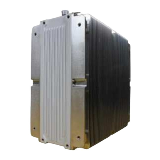
RU Hardware Feature RU Profile RU Profile The following figure shows the different profile views of the RU. FRONT SIDE REAR BOTTOM Figure 3 RU Profile Views Fujitsu and Fujitsu Customer Use Only · Issue 1.1, May 2021 Release 1.0... -
Page 20: Ru Specifications
400 x 380 x 200 mm Weight < 29.0 kg max (except the mounting brackets, other options) Power consumption < 1300 W (under all operational condition, with AISG) Fujitsu and Fujitsu Customer Use Only · Issue 1.1, May 2021 Release 1.0... - Page 21 Alarms. Noise floor measurement The RU supports the function of measuring the Received Total Wideband Power (RTWP), when initiated by EMS or when initiated by the DU. Fujitsu and Fujitsu Customer Use Only · Issue 1.1, May 2021 Release 1.0...
- Page 22 Service interruption is defined as the preparation for the RU to establish the M/S-Plane with the host device. Mean Time Between > 175,320 hours at RU internal temperature. Failures (MTBF) RU MTBF exceeds 20 years or higher. YRR (FRR) < 2% Fujitsu and Fujitsu Customer Use Only · Issue 1.1, May 2021 Release 1.0...
-
Page 23: Environmental Specifications
The temperature is monitored from the start of the device, and the Cold start state is released when the temperature reaches −20 ℃ and reported to the EMS. Air Pressure 70-106 kPa Compliant to IEC 60068-2 standards Fujitsu and Fujitsu Customer Use Only · Issue 1.1, May 2021 Release 1.0... -
Page 24: Transport And Storage Requirements
0.5 °C/min (32.9 °F/min) Change of Temperature Vibration ETSI EN 300 019-2-4, Severity class 1 2.2.3 Product Safety Specification UL62368-1 2nd edition Basic Specification Outdoor Specification UL 50E (UL60950-22) CSA-C22.2 Fujitsu and Fujitsu Customer Use Only · Issue 1.1, May 2021 Release 1.0... -
Page 25: Electromagnetic Compatibility
Radio must meet performance criteria before and after completion of test. Immunity Specification Table 6 Specification In 3GPP 38.113 Detail Phenomenon Application Reference Standard Criteria Specification RF electromagnetic field (80… Enclosure IEC 61000-4-3 Radiated Immunity 6000 MHz) Fujitsu and Fujitsu Customer Use Only · Issue 1.1, May 2021 Release 1.0... -
Page 26: Radiated Immunity
Contact discharge ±8 kV Air discharge Performance Criteria Fast Transients Common Mode 3GPP 38.113 Test standard IEC 61000-4-4 0.5 kV Performance criteria Power consistency, RET consistency Injected port Fujitsu and Fujitsu Customer Use Only · Issue 1.1, May 2021 Release 1.0... -
Page 27: Rf Common Mode
L-FG (Common mode) ±4 kV(10/700 μs) Performance criteria RET port Injected port RF Port Level 4 IEC61000-4-5 (Combination wave) L-FG (Common mode) ±20 kV (1.2/50 μs) Performance criteria RF port Injected port Fujitsu and Fujitsu Customer Use Only · Issue 1.1, May 2021 Release 1.0... -
Page 28: Ru Downlink/Uplink Default Parameters
2200 2190 1995 2020 2010 BW (MHz) Power/port (dBm) 37.8 47.8 47.8 36.0 46.0 46.0 Up Link Frequency (MHz) 1710 1780 1745 1695 1710 1705 BW (MHz) Fujitsu and Fujitsu Customer Use Only · Issue 1.1, May 2021 Release 1.0... -
Page 29: Antenna Configuration
The RU can transmit maximum 80 W per antenna port, and the maximum output power is 320 W. The features of the antenna configuration are listed in the following table. Fujitsu and Fujitsu Customer Use Only · Issue 1.1, May 2021... - Page 30 Band 66: 60 W Port#D Band 70: 40 W Band 66: 60 W Total Power 320 W Note: All band combinations support a maximum power output of 320 W. Fujitsu and Fujitsu Customer Use Only · Issue 1.1, May 2021 Release 1.0...
-
Page 31: Carrier Configuration
5 MHz 20 MHz 32.0 40.0 1.60 H: Bandwidth is 1995…2000 nm and frequency is 5 MHz. AWS-4: Bandwidth is 2000…2020 nm and frequency is 20 MHz. Fujitsu and Fujitsu Customer Use Only · Issue 1.1, May 2021 Release 1.0... - Page 32 5 MHz 20 MHz — 32.0 — 40.0 1.60 — — — — — — 20 MHz 5 MHz 20 MHz — 12.0 48.0 — 60.0 2.40 — Fujitsu and Fujitsu Customer Use Only · Issue 1.1, May 2021 Release 1.0...
- Page 33 20 MHz — 25.7 34.3 — 60.0 1.71 — 15 MHz — — — — 20 MHz 15 MHz 20 MHz — 17.1 22.9 — 40.0 1.14 — Fujitsu and Fujitsu Customer Use Only · Issue 1.1, May 2021 Release 1.0...
- Page 34 5 MHz 10 MHz 20 MHz 17.1 34.3 60.0 1.71 — — — — — 20 MHz 5 MHz 10 MHz 20 MHz 17.1 34.3 60.0 1.71 Fujitsu and Fujitsu Customer Use Only · Issue 1.1, May 2021 Release 1.0...
- Page 35 5 MHz 10 MHz 20 MHz 17.1 34.3 60.0 1.71 — — 5 MHz — — 20 MHz 5 MHz 10 MHz 20 MHz 17.1 34.3 60.0 1.71 Fujitsu and Fujitsu Customer Use Only · Issue 1.1, May 2021 Release 1.0...
- Page 36 15 MHz 20 MHz 22.5 30.0 60.0 1.50 15 MHz — 5 MHz — — 20 MHz 5 MHz 15 MHz 20 MHz 22.5 30.0 60.0 1.50 Fujitsu and Fujitsu Customer Use Only · Issue 1.1, May 2021 Release 1.0...
- Page 37 10 MHz 20 MHz 15.0 15.0 30.0 60.0 1.50 — — — — — 20 MHz 10 MHz 10 MHz 20 MHz 15.0 15.0 30.0 60.0 1.50 Fujitsu and Fujitsu Customer Use Only · Issue 1.1, May 2021 Release 1.0...
- Page 38 10 MHz 15 MHz 20 MHz 13.3 20.0 26.7 60.0 1.33 15 MHz — — 20 MHz 10 MHz 15 MHz 20 MHz 13.3 20.0 26.7 60.0 1.33 Fujitsu and Fujitsu Customer Use Only · Issue 1.1, May 2021 Release 1.0...
- Page 39 10 MHz 20 MHz 20 MHz 12.0 24.0 24.0 60.0 1.20 — 20 MHz 20 MHz 10 MHz 20 MHz 20 MHz 12.0 24.0 24.0 60.0 1.20 Fujitsu and Fujitsu Customer Use Only · Issue 1.1, May 2021 Release 1.0...
- Page 40 20 MHz 20 MHz 16.4 21.8 21.8 60.0 1.09 20 MHz — — — 20 MHz 15 MHz 20 MHz 20 MHz 16.4 21.8 21.8 60.0 1.09 Fujitsu and Fujitsu Customer Use Only · Issue 1.1, May 2021 Release 1.0...
- Page 41 AWS-1 E AWS-1 F AWS-3 G AWS-3 H AWS-3 I AWS-3 J 1C Uplink — — — — — — — — — — — — — — Fujitsu and Fujitsu Customer Use Only · Issue 1.1, May 2021 Release 1.0...
- Page 42 — — — 15 MHz — — — — — — — — — — — — — 15 MHz — — — — — — — Fujitsu and Fujitsu Customer Use Only · Issue 1.1, May 2021 Release 1.0...
- Page 43 — 5 MHz — — — — — — — — — — — 10 MHz 5 MHz — — — — — — — — — Fujitsu and Fujitsu Customer Use Only · Issue 1.1, May 2021 Release 1.0...
- Page 44 — — — — — — — — 5 MHz — — — — 10 MHz — — — — — — — 5 MHz — — Fujitsu and Fujitsu Customer Use Only · Issue 1.1, May 2021 Release 1.0...
- Page 45 — 20 MHz 5 MHz — — — — — — — — — — — — — 5 MHz 20 MHz — — — — — Fujitsu and Fujitsu Customer Use Only · Issue 1.1, May 2021 Release 1.0...
- Page 46 — 10 MHz — — — — — — 10 MHz — — — — 10 MHz — — — — — — — — 10 MHz Fujitsu and Fujitsu Customer Use Only · Issue 1.1, May 2021 Release 1.0...
- Page 47 — — — — — — 10 MHz — — — — 15 MHz — — 15 MHz — — 10 MHz — — — — — Fujitsu and Fujitsu Customer Use Only · Issue 1.1, May 2021 Release 1.0...
- Page 48 — 20 MHz 20 MHz — — — — — 10 MHz — — — — — 20 MHz — — — 10 MHz — — — Fujitsu and Fujitsu Customer Use Only · Issue 1.1, May 2021 Release 1.0...
- Page 49 — 15 MHz — — — — 20 MHz — — — 15 MHz — — — — — — — 20 MHz 15 MHz — — Fujitsu and Fujitsu Customer Use Only · Issue 1.1, May 2021 Release 1.0...
- Page 50 — 20 W 80 W 10 MHz 5 MHz 5 MHz 10 W + 10 W 80 W 5 MHz 5 MHz — 10 W 40 W Fujitsu and Fujitsu Customer Use Only · Issue 1.1, May 2021 Release 1.0...
- Page 51 20 MHz 15 MHz 5 MHz — 15 W + 5 W 80 W 20 MHz 10 MHz 10 MHz — 10 W + 10 W 80 W Fujitsu and Fujitsu Customer Use Only · Issue 1.1, May 2021 Release 1.0...
- Page 52 — 10 W 40 W 10 MHz 5 MHz 5 MHz — 5 W + 5 W 40 W 5 MHz 5 MHz — — 20 W Fujitsu and Fujitsu Customer Use Only · Issue 1.1, May 2021 Release 1.0...
-
Page 53: Functional Block Diagram
▪ The iFFT/FFT block performs IQ conversion/inverse conversion of the uplink ad downlink U-planes. ▪ The RACH Block is a processing function for the random access channel. Fujitsu and Fujitsu Customer Use Only · Issue 1.1, May 2021 Release 1.0... - Page 54 ▪ IQ signals in Lower Layer Split (LLS) and monitoring signals are Lower Layer Baseband transmitted between a higher NR system CU device and TRX by an optical fiber according to an eCPRI format. Fujitsu and Fujitsu Customer Use Only · Issue 1.1, May 2021 Release 1.0...
-
Page 55: External Interface
The FullAXS mini (product number: 2061981) or the compatible connector is adopted as the waterproof connector. The product number of external cable plug is 2061980. eCPRI: 10 Gb/s at least. Electrical interface Electrical interface is compliant to INF-8074. Fujitsu and Fujitsu Customer Use Only · Issue 1.1, May 2021 Release 1.0... -
Page 56: Dc Power And Ground Ports
The water ingress protection is not required for these caps. The RU has two M6 bolts and nuts for lug ground connection. Fujitsu and Fujitsu Customer Use Only · Issue 1.1, May 2021 Release 1.0... -
Page 57: Ret Port
IP65 is supported for the function of waterproofing with fitted cap or connected cable. No guarantee for waterproof when cap or cable is loose contact or not connected. Table 16 RET Interface Connector Pin Assignment Description Not connected Not connected Fujitsu and Fujitsu Customer Use Only · Issue 1.1, May 2021 Release 1.0... -
Page 58: Debug/Test Port
■ One Operational, Green color ■ One Interfaces, Green color (one corresponding to eCPRI port) The software controls the on/off and blinking LEDs according to the status of the RU. Fujitsu and Fujitsu Customer Use Only · Issue 1.1, May 2021... - Page 59 Minor Alarm Green blinking Red blinking Green on L1 disconnection Green off L1 link found Green blinking (M-Plane not found) L1 & M-Plane link found Green on Fujitsu and Fujitsu Customer Use Only · Issue 1.1, May 2021 Release 1.0...
- Page 60 Status of MMI LEDs Blink Steady ON Operational LED No power Communication with BBU is not Operation found Fault LED No fault Warning Alarm eCPRI interface LED Not operating Operation Fujitsu and Fujitsu Customer Use Only · Issue 1.1, May 2021 Release 1.0...
-
Page 61: Tx Control Function
Dual-band RU has a transmit power of 80 W/Port and has two transmit modes, depending on the transmit power of each band. 1. n70 + n66: 20 W + 60 W 2. n70 + n66: 40 W + 40 W Fujitsu and Fujitsu Customer Use Only · Issue 1.1, May 2021 Release 1.0... - Page 62 Port #A n66 Message DL Gain: Maximum Output Power -6db M66 Maximum Output Power < 40W? Switch Power Mode i) -> (ii) n70 + n66: 20W + 60W Fujitsu and Fujitsu Customer Use Only · Issue 1.1, May 2021 Release 1.0...
-
Page 63: Performance Requirement
The RU supports Telecom Slave Clock (T-TSC) to G8275.1 and does not support G8275.2. The RU provides additional noise filtering to filter fronthaul interface dynamic noise which will help meet 3GPP frequency accuracy requirement. Fujitsu and Fujitsu Customer Use Only · Issue 1.1, May 2021... -
Page 64: Counter
RTXM228-424-C74 APAC Opto Electronics Inc. LE48-H3L-TI-N-LF 2.9.2 Radio Performance The RU meets the radio specifications described in this section under all environmental conditions specified, unless otherwise noted. Fujitsu and Fujitsu Customer Use Only · Issue 1.1, May 2021 Release 1.0... -
Page 65: General Specifications
TX and RX Frequency Interval n70: 25 MHz n66: 330 MHz Sub carrier spacing 5G-NR 15 kHz, 30 kHz Carrier Configurations Refer to Carrier Configuration 15 MHz is not currently supported Fujitsu and Fujitsu Customer Use Only · Issue 1.1, May 2021 Release 1.0... -
Page 66: Transmitter Specification
Operating Band 617 MHz…652 MHz NR n70 717 MHz…728 MHz NR n66 Frequency Error < ±0.05 ppm Specification ±12 Hz Test Tolerance VSWR < 1.5 @antenna port Fujitsu and Fujitsu Customer Use Only · Issue 1.1, May 2021 Release 1.0... - Page 67 < 5 MHz (99% Bandwidth) 5 MHz < 10 MHz (99% Bandwidth) 10 MHz < 20 MHz (99% Bandwidth) 20 MHz < 25 MHz (99% Bandwidth) 25 MHz Fujitsu and Fujitsu Customer Use Only · Issue 1.1, May 2021 Release 1.0...
- Page 68 Applicable in case the base station channel bandwidth of the NR carrier transmitted at the other edge of the gap is 5, 10, 15, 20 MHz. With SCS that provides largest transmission bandwidth configuration (BW config is the transmission bandwidth configuration of the assumed adjacent channel carrier. config Fujitsu and Fujitsu Customer Use Only · Issue 1.1, May 2021 Release 1.0...
- Page 69 The requirement is not applicable when Δf < 10 MHz. Table 25 Spurious Emissions Frequency Range Maximum Level* Measurement Bandwidth 9 kHz…150 kHz < –36 dBm 1 kHz Fujitsu and Fujitsu Customer Use Only · Issue 1.1, May 2021 Release 1.0...
- Page 70 < –30 dBm 1 MHz 1427 MHz…1517 MHz < –96 dBm 100 kHz 1517 MHz…1518 MHz < –52 dBm 1 MHz 1518 MHz…1525 MHz < –30 dBm 1 MHz Fujitsu and Fujitsu Customer Use Only · Issue 1.1, May 2021 Release 1.0...
- Page 71 < –96 dBm 100 kHz 4200 MHz…4400 MHz < –30 dBm 1 MHz 4400 MHz…5000 MHz < –96 dBm 100 kHz 5000 MHz…5091 MHz < –70 dBm 100 kHz Fujitsu and Fujitsu Customer Use Only · Issue 1.1, May 2021 Release 1.0...
- Page 72 Modulation Quality Table 26 Error Vector Magnitude (EVM) Modulation Scheme Required EVM Test Tolerance QPSK ≤ 17.5% 1.0% 16QAM ≤ 12.5% 64QAM ≤ 8% 256QAM ≤ 3.5% Fujitsu and Fujitsu Customer Use Only · Issue 1.1, May 2021 Release 1.0...
- Page 73 >1 MHz bands immediately outside and adjacent to the frequency block have the following specifications: 200 kHz (Max) 200 kHz (Max) Outside 1 MHz, the reference bandwidth (1 MHz) is applied. Fujitsu and Fujitsu Customer Use Only · Issue 1.1, May 2021 Release 1.0...
-
Page 74: Receiver Specification
Mean Power (kHz) Mean Power (dBm) Signal (MHz) Channel (dBm)/BW config G-FR1-A2-1 −70.7 −82.5 Additive White Gaussian Noise (AWGN) G-FR1-A2-1 −70.7 −79.3 AWGN G-FR1-A2-1 −70.7 −77.5 AWGN Fujitsu and Fujitsu Customer Use Only · Issue 1.1, May 2021 Release 1.0... - Page 75 Gap (MHz) 5, 10, 15, 20 + 6 dB –43 ±7.5 5 MHz DFT-s-OFDM NR signal 15 kHz SCS, 25 RBs 15 MHz is not currently supported. Fujitsu and Fujitsu Customer Use Only · Issue 1.1, May 2021 Release 1.0...
- Page 76 WA NR Band 41 2496…2690 CW carrier WA NR Band 66 2110…2200 CW carrier WA NR Band 70 1995…2020 CW carrier Digital TV (DTV) band 470…698 CW carrier Fujitsu and Fujitsu Customer Use Only · Issue 1.1, May 2021 Release 1.0...
- Page 77 Received (MHz) block Edge Inside A Sub-block Gap (kHz) ±360 ±1420 5 MHz DFT-s-OFDM NR signal, 1 RB ±370 ±1960 5 MHz DFT-s-OFDM NR signal, 1 RB Fujitsu and Fujitsu Customer Use Only · Issue 1.1, May 2021 Release 1.0...
-
Page 78: Power Supply
(Fc), where the Fc is defined for base station channel bandwidth of the wanted signal. The aggregated wanted and interfering signal must be centered in the base station channel bandwidth of the wanted signal. 2.9.3 Power Supply Fujitsu and Fujitsu Customer Use Only · Issue 1.1, May 2021 Release 1.0... -
Page 79: Electrical Specifications
−75 V (9.5 ±0.5 ms) (ATIS-0600315) Over Voltage Transient Criteria: non destruction DC Power Specification 36.5 Amps maximum DC Current 1300 W maximum (include AISG) DC Power Consumption Fujitsu and Fujitsu Customer Use Only · Issue 1.1, May 2021 Release 1.0... -
Page 80: Ordering Information
Ordering Information Ordering Information In this chapter: Radio Unit Mounting Kits Accessories Fujitsu and Fujitsu Customer Use Only · Issue 1.1, May 2021 Release 1.0... -
Page 81: Radio Unit
Ordering Information Radio Unit Radio Unit Unit Name Part Number Dual-Band Radio (n66, n70) TA08025-B604 Fujitsu and Fujitsu Customer Use Only · Issue 1.1, May 2021 Release 1.0... -
Page 82: Mounting Kits
▪ Fasteners ▪ 2 x M8 eye bolts Eye Bolt Kit 10-578-000 F6-WB8-200 ▪ 2 x M8 spring washer SS F6-WM8-200 ▪ 2 x M8 washer SS Fujitsu and Fujitsu Customer Use Only · Issue 1.1, May 2021 Release 1.0... -
Page 83: Accessories
Optical cable connects from RU eCPRI optical port to the DU Optics, SFP 10G SFP Antenna Bracket Allows the antenna to mount to RU Antenna Transmits and receives radio signals Fujitsu and Fujitsu Customer Use Only · Issue 1.1, May 2021 Release 1.0... -
Page 84: Installation
The following sections describe how to attach the RU to a wall or pole using a mounting kit. Caution: Use care when handling the RU, as it is heavy. Fujitsu Attention: Manipulez le RU avec précaution car il est lourd. Fujitsu recommends installing the RU on a two-person team to avoid recommande d'installer le RU sur deuxéquipe de personnes pour... -
Page 85: Unpack
Place the RU on packing foam or an anti-static mat. Step 3 Remove all packing foam that is around the heat sink and unit. ✓ This task is complete. Fujitsu and Fujitsu Customer Use Only · Issue 1.1, May 2021 Release 1.0... -
Page 86: Mounting
■ The wall mounting surface and anchors must be able to withstand up to 240 lbs (108.862 kg) of weight. The following graphic shows an RU attached to a pole with a pole mounting kit. Figure 9 Pole Mount Final Result Fujitsu and Fujitsu Customer Use Only · Issue 1.1, May 2021 Release 1.0... - Page 87 The following graphic shows an RU mounted on a wall with a wall mounting kit. Figure 10 Wall Mount Final Result The following graphic shows how to mount an RU to a pole using a pole mounting kit. Fujitsu and Fujitsu Customer Use Only · Issue 1.1, May 2021 Release 1.0...
- Page 88 Bolt, HEX, HD, 3/16-16 x 10.0 L, 18-8 SS Washer, Split, M10, SS Bolt, HEX HD, M10 x 30L, SS Bolt, HEX HD, M10 x 40L, SS Fujitsu and Fujitsu Customer Use Only · Issue 1.1, May 2021 Release 1.0...
- Page 89 M10, SS, Split Washer Eye Bolts Radio Unit L-Brackets with Hardware The following figure shows how to mount an RU to a outdoor wall using a wall mounting kit. Fujitsu and Fujitsu Customer Use Only · Issue 1.1, May 2021 Release 1.0...
- Page 90 Bolt, Hex HD, M10 X 40 mm, SS Insulator, Step Washer, Flat, M10 Insulator, Washer, Flat, M10 Plate, Wall Mount Screw Kit, Wall Mount Washer, Flat, M10, SS Fujitsu and Fujitsu Customer Use Only · Issue 1.1, May 2021 Release 1.0...
- Page 91 L-Brackets with Hardware Only used for mounting onto a wood surface. If mounting on another surface, for example, concrete, brick, or unistrut, the proper mounting equipment will need to be acquired. Fujitsu and Fujitsu Customer Use Only · Issue 1.1, May 2021...
-
Page 92: Installation Precautions
à 45 ° C selon UL62368-1 / 60950-22. ▪ This device may receive interferences that may cause ▪ Cet appareil peut recevoir des interférences susceptibles d'entraîner un undesired operation. fonctionnement indésirable. Fujitsu and Fujitsu Customer Use Only · Issue 1.1, May 2021 Release 1.0... - Page 93 • These radios are designed to withstand weather nuisibles. • Ces radios sont conçues pour résister aux conditions météorologiques conditions typically encountered when installed généralement rencontrées lorsqu'elles sont installées à l'extérieur. outdoors. Fujitsu and Fujitsu Customer Use Only · Issue 1.1, May 2021 Release 1.0...
-
Page 94: Returning Of Defective Equipment
Returning of Defective Equipment Returning of Defective Equipment Defective equipment must be returned to Fujitsu for repair or replacement which requires a Return Material Authorization (RMA). If you have purchased TAC support, contact FTAC to assist with equipment failures. FTAC can help with a Unit... -
Page 95: Ru Installation
Note: Use care when handling the RU, as it is heavy. Fujitsu recommends installing the RU on a two-person team to avoid damage to the unit or injury to the user. If the RU is to be installed at a high location, Fujitsu recommends using lifting equipment to hoist the RU by a pair of eye bolts mounted on the RU. -
Page 96: Attach L-Brackets And Eye Bolts
■ Power tools (optional) ■ Metric and SAE toolkit Note: If the RU is to be installed at a high location, Fujitsu recommends using lifting equipment to hoist the RU by a pair of eye bolts mounted on the RU. -
Page 97: Attach Ru Mounting Adapter Plate
This procedure describes how to attach the mounting adapter plate to the RU. Prerequisites: ■ Loctite LB 8012 or equivalent lubricant applied to all bolts ■ 17 mm socket ■ 5/8 in. wrench Fujitsu and Fujitsu Customer Use Only · Issue 1.1, May 2021 Release 1.0... - Page 98 Aligning Mounting Adapter Plate and Bushings Step 3 Secure the mounting adapter plate to the L-Brackets using M10 x 30 screws with flat and split washers as shown in the following graphic. Fujitsu and Fujitsu Customer Use Only · Issue 1.1, May 2021 Release 1.0...
-
Page 99: Attach Ru To Pole
This procedure describes how to attach a RU to a pole using a pole mount kit. Prerequisites: ■ Loctite LB 8012 or equivalent lubricant applied to bolts ■ 17 mm socket ■ 13 mm socket ■ 5/8 in. wrench ■ Torque wrench Fujitsu and Fujitsu Customer Use Only · Issue 1.1, May 2021 Release 1.0... - Page 100 RU before starting this procedure. déconnectés de l'EF avant de commencer cette procédure. Caution: The RU is heavy. Fujitsu recommends removing the RU on Attention: Le RU est lourd. Fujitsu recommande de retirer l'EF d'une a two-person team to avoid damage to the unit or injury to the user.
- Page 101 Connect the small crossmembers from opposite side of pole to the large crossmembers on the mounting plate using four 3/8-16 x 10L bolts, washers, and nuts as shown in Figure 17. Secure them together using a 17 mm socket. Note: Fujitsu recommends a second person assist with this step. Figure 17 Pole Mount Crossmembers Step 5 Add jam nuts to each 3/8-16 x 10L bolts and secure until tightened.
- Page 102 Step 7 Mount the RU to the pole by aligning the hooks on the plate adapter with the two holes at the top of the wall mounting plate. Fujitsu and Fujitsu Customer Use Only · Issue 1.1, May 2021 Release 1.0...
- Page 103 Do not tighten the bolts yet. Step 9 Secure the L-brackets to the mounting adapter plate using two M10 x 40 mm bolts, split washers, and flat washers. Fujitsu and Fujitsu Customer Use Only · Issue 1.1, May 2021 Release 1.0...
- Page 104 Figure 20 Connect L-Brackets to Plate Step 10 Torque each bolt on the top and bottom of the mounting plate using a 11/16 socket to 27 Nm. Fujitsu and Fujitsu Customer Use Only · Issue 1.1, May 2021 Release 1.0...
-
Page 105: Attach Ru To Wall
■ Loctite LB 8012 or equivalent lubricant applied to all bolts ■ 17 mm socket ■ 5/8 in. wrench ■ Philips screw driver ■ Power tools (optional) ■ Metric and SAE toolkit Fujitsu and Fujitsu Customer Use Only · Issue 1.1, May 2021 Release 1.0... - Page 106 RU before starting this procedure. déconnectés de l'EF avant de commencer cette procédure. Caution: The RU is heavy. Fujitsu recommends removing the RU on Attention: Le RU est lourd. Fujitsu recommande de retirer l'EF d'une a two-person team to avoid damage to the unit or injury to the user.
- Page 107 Align the sticky side of the bushings with the threaded holes on the lower front lip of the wall plate and stick them in place as shown in the following graphic. Fujitsu and Fujitsu Customer Use Only · Issue 1.1, May 2021...
- Page 108 Step 4 Align the holes on the Wall Mount Plate Adapter with the holes on the top of the Wall Mount Plate and hook it in place. Fujitsu and Fujitsu Customer Use Only · Issue 1.1, May 2021 Release 1.0...
- Page 109 Ensure the shoulder of the stepped bushing is perfectly fit inside of the hole on the L-bracket for proper alignment. Fujitsu and Fujitsu Customer Use Only · Issue 1.1, May 2021...
- Page 110 Insulating Bushing Split Washer Figure 26 Securing RU to Wall Mount Plate Step 6 Torque all four M10 bolts to 27 Nm to secure the RU in place. Fujitsu and Fujitsu Customer Use Only · Issue 1.1, May 2021 Release 1.0...
- Page 111 Installation RU Installation Figure 27 Wall Mount Final Result Continue with the next task. Fujitsu and Fujitsu Customer Use Only · Issue 1.1, May 2021 Release 1.0...