
Related Manuals for Canon GC-201


Summary of Contents for Canon GC-201
- Page 1 CANON Digital Galvano Scanner System GM-1000 Series GC-201 Users Manual Rev. 1.20 Be sure to read this guide before using the product. Keep this guide carefully for future use.
- Page 2 ・ Since this product is a precision device, use it under the specified environmental conditions. ・ Do not store or transport this product in a place exposed to direct sunlight, moisture, dust, or temperature of 60ºC or higher. CANON Digital Galvano Scanner System GM-1000 Series Users Manual 1.20...
-
Page 3: Table Of Contents
4.2.1.1. Measurement Data Display Zoom Method ... 54 4.2.1.2. Reference Data Comparison Method ... 56 4.3. Raster Scan ... 59 4.4. Position Command Input by High-speed Serial Communication ... 61 CANON Digital Galvano Scanner System GM-1000 Series Users Manual 1.20 ... 22 ... 26 ... - Page 4 Appendix ... 132 11.1. Firmware Update ... 132 11.1.1. Writing Procedure ... 133 11.2. Parameter Changes from the Number of Encoder Divisions ... 137 CANON Digital Galvano Scanner System GM-1000 Series Users Manual 1.20 ... 70 ... 129 ... 62...
-
Page 5: Product Outline
Product Outline 1.1. Features The Canon Digital Galvano Scanner System is fully digitally controlled with a high-precision optical encoder on the galvano motor and a high-speed digital signal processor (DSP) on the controller. This system has the following features: High positioning precision... -
Page 6: Specifications
Storage temperature and humidity Note: The above operating temperature and humidity conditions depend on the operating and heat radiation conditions. Stopper Part names Encoder CANON Digital Galvano Scanner System GM-1000 Series Users Manual 1.20 GM-1010 Φ8 to φ10 φ10 to φ15 ±20 deg... -
Page 7: Controller (Gc-201)
Mounting screw hole (M3 × 4) Mounting screw hole (φ3.5 × 4) Digital board (upper) CANON Digital Galvano Scanner System GM-1000 Series Users Manual 1.20 GC-201 100 kHz Peak 10 A (each axis) RS-232C , High-speed serial communication(XY2-100) Digital notch filter ×2... -
Page 8: Dimensions
2.3. Dimensions GM-1010 Encoder cable GM-1015 Encoder cable CANON Digital Galvano Scanner System GM-1000 Series Users Manual 1.20 32 (Clamp area) Motor cable 42 (Clamp area) Motor cable... - Page 9 GM-1020 42.7 51.4 (Clamp Area) Encoder Cable Motor Cable CANON Digital Galvano Scanner System GM-1000 Series Users Manual 1.20...
- Page 10 GC-201 CANON Digital Galvano Scanner System GM-1000 Series Users Manual 1.20 4-M3 4- φ 3.5...
-
Page 11: Power Supply
±5°, 200Hz) +5 V ± 5% (For control circuit) 2.5. Connections Digital input/output CANON Digital Galvano Scanner System GM-1000 Series Users Manual 1.20 Peak 10 A × 2 axes RMS 2.5 A × 2 axes 2.8 A IF board +24 V power... - Page 12 Note: Connecting the power +24 V, and GND in reverse will damage the GC-201 controller. Take caution when connecting. Connecting the power +5 V, and GND in reverse will damage the GC-201 controller. Take caution when connecting. CANON Digital Galvano Scanner System GM-1000 Series Users Manual 1.20...
-
Page 13: Connector And Pin Assignment
+24 V power supply ④ RS-232C ⑤ High-speed serial communication ⑥ Digital input/output ⑦ Analog monitor ⑧ Fan power supply (+24 V) ⑨ CANON Digital Galvano Scanner System GM-1000 Series Users Manual 1.20 ⑦ ③ ① ② ⑥ ⑤ ④ ⑨... - Page 14 Board side Cable side (Connector pin assignment) Pin No. Send data (Signal level complying with RS-232C) Receive data (Signal level complying with RS-232C) CANON Digital Galvano Scanner System GM-1000 Series Users Manual 1.20 Model No. S2P-VH VHR-2N Signal Description Model No.
- Page 15 GC-LVDS - Receiver: SN65LVDS32 (TI), Driver: SN65LVDS179 (TI) ⑦ Digital I/O See 5.1. “Connector Pin Assignment” ⑧ Analog Monitor See 5.1. “Connector Pin Assignment” CANON Digital Galvano Scanner System GM-1000 Series Users Manual 1.20 Model No. SM12B-PASS-1-TB PAP-12V-S Signal Name...
- Page 16 ⑨ Cooling Fan Power Supply (Connector model number) Connector Board side Cable side (Connector pin arrangement) Pin No. +24 V Output (No connection) (No connection) CANON Digital Galvano Scanner System GM-1000 Series Users Manual 1.20 Model No. S04B-PASK-2 PAP-04V-S Signal Description Manufacturer...
-
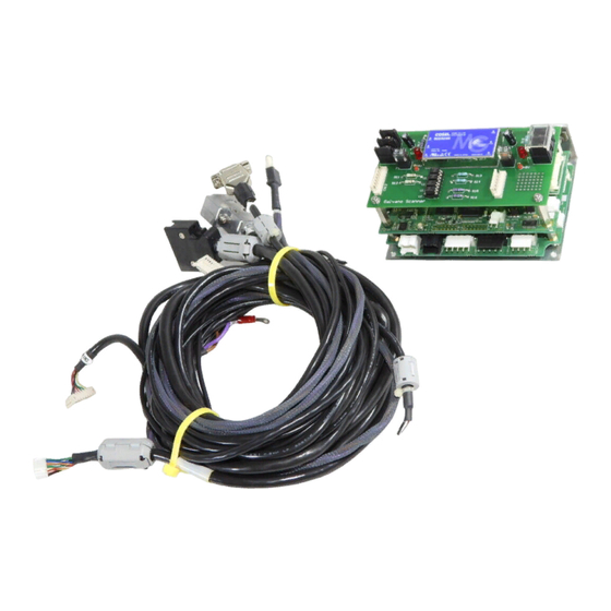
Page 17: Optional Cables
Option cables ① ② ③ ④ ① Power Cable +5 V ② Power Cable +24 V CANON Digital Galvano Scanner System GM-1000 Series Users Manual 1.20 Power cable (+5 V) Power cable (+24 V) RS-232C cable High-speed serial communication cable... - Page 18 ③ RS-232C Cable PC side (D-sub 9 pin) ④ High-Speed Serial Communication Cable PC side (D-sub 25pin) CANON Digital Galvano Scanner System GM-1000 Series Users Manual 1.20 Signal Clock - FS - Data (Axis 1) - Data (Axis 2) -...
-
Page 19: Control Specifications
2.8. Control Specifications The controller (GC-201) is operated by: • RS-232C command input • High-speed serial communication communication command input - Raster scan and step movement etc. can be performed easily. - In order to obtain synchronization with external equipment, operation can be started with an external trigger signal. - Page 20 When there is no signal input, a Clock Lack error occurs. (See 10.2. “Errors”) After an error occurs, and input of a high-speed serial communication signal begins correctly, operation begins automatically from the high-speed serial communication signal. CANON Digital Galvano Scanner System GM-1000 Series Users Manual 1.20...
-
Page 21: Number Of Encoder Pulses
2.8.1. Number of Encoder Pulses This section explains the relationship between the galvano scanner motor rotating angle and the number of encoder pulses. Control commands and some of the parameter angle settings use the number of encoder pulses. The controller divides one encoder cycle into 8,192, and this is the number of encoder pulses. -
Page 22: Rs-232C Command Input
Raster scan (Continuous oscillation of a certain angle at a fixed frequency) (Communication specifications) Wiring Communication rate Data length Stop bit Parity Data format Delimiter code CANON Digital Galvano Scanner System GM-1000 Series Users Manual 1.20 Cross wiring 38400 bps 8 bits None ASCII code LF (0x0a) or CR (0x0d) - Page 23 1 or 2 E.g. Servo ON ID = 4 A1C004 / 1 (LF) (ASCII code: 0x41 0x31 0x43 0x30 0x30 0x34 0x2f 0x31 0x0a) CANON Digital Galvano Scanner System GM-1000 Series Users Manual 1.20 Command ID Command ID Decimal, 3-digit (See 7.1 for details)
- Page 24 Parameters of the GC-201 can be changed by the following sending method to the controller. Also in response to parameters sent, the controller always returns a reply with data. The data contents depend on the command. (For details, see 9.2. “Parameter Details”) When a parameter is changed, in order to start up with the same setting the next time power is turned on, it is necessary to write the changed parameter to the ROM.
- Page 25 1 or 2 E.g. LQ gain parameter ID = 6 E1P006 / 4500 (LF) (ASCII code: 0x45 0x31 0x50 0x30 0x30 0x36 0x2f 0x30 0x0a) CANON Digital Galvano Scanner System GM-1000 Series Users Manual 1.20 Parameter ID Parameter ID Decimal, 3-digit (See 7.1 for details)
-
Page 26: High-Speed Serial Communication
As indicated in the above timing diagram, it is necessary to always continuously input the CLK, FS, and DAT signals to the GC-201. In the event that the signal is disconnected, or the signal’s timing is incorrect, the GC-201 will output an error signal (Clock Lack). (For details, See 10.2. “Errors”.) When switching to high-speed serial communication mode, or starting up in high-speed serial communication mode when turning on the controller’s power supply, input of the high-speed serial... - Page 27 Note: The length of data input in the GC-201 is always 20 bit (every 100 kHz). The bits of the target position data that get used and sent are switched from within 20 bit data.
- Page 28 DATA (AXIS 1) D19 D18 D17 D16 D15 D14 D13 D12 D11 D10 D9 DATA (AXIS 2) D19 D18 D17 D16 D15 D14 D13 D12 D11 D10 D9 CANON Digital Galvano Scanner System GM-1000 Series Users Manual 1.20 D15 D14 D13 D12 D11 D10 D9...
- Page 29 When set to the factory default, rotation is only possible up to angles above. If a greater angle is specified, set a magnification by using the following parameter. CANON Digital Galvano Scanner System GM-1000 Series Users Manual 1.20 Target position data value...
- Page 30 -1.44 × 2 deg ~ 1.44 × 2 deg (GM-1010) -0.96 × 2 deg ~ 0.96 × 2 deg (GM-1015, 1020) The command resolution will be two times CANON Digital Galvano Scanner System GM-1000 Series Users Manual 1.20 Parameter ID Data Magnification ×1000...
- Page 31 Maximum movable range of the motor is set with Parameter ID = 0, 1 (CW limit, CCW limit). The position data of high-speed serial communication can not exceed this range. CANON Digital Galvano Scanner System GM-1000 Series Users Manual 1.20...
-
Page 32: Origin Offset
= High speed serial communication command position + High speed serial communication offset So, Current position data is not equal to High speed serial communication command position that you specify. CANON Digital Galvano Scanner System GM-1000 Series Users Manual 1.20 Parameter ID... -
Page 33: High-Speed Serial Communication Motor Drive Timing
The following diagram indicates actual motor drive signal output timing when the high-speed serial communication position command is received. COMMAND COMMAND XY-2 COMMAND XY-2 COMMAND FRAME SYNC FRAME SYNC DSP Sampling Clock DSP Sampling Clock CANON Digital Galvano Scanner System GM-1000 Series Users Manual 1.20 10us 10us Target Target Target Target Position1 Position1... -
Page 34: Status (High-Speed Serial Communication Sts)
S06 (reserve) S05 Axis2 INPOS 0 S04 Axis1 INPOS 0 S03 (reserve) S00 (reserve) CANON Digital Galvano Scanner System GM-1000 Series Users Manual 1.20 0: Controller condition 1 1: Controller condition 2 2: Current position (Axis 1) 3: Current position (Axis 2) - Page 35 0x80000 position Minimum 0x0000F position CANON Digital Galvano Scanner System GM-1000 Series Users Manual 1.20 (See 5.3. “Digital Input-Output Function”. Same as Axis 1 Error 1, Axis 2 Error 1) : Alarm output (priority low) (See 5.3. “Digital Input-Output Function”. Same as Axis 1 Error 2, Axis 2...
- Page 36 Axis Flag = 0 Axis 1 Axis Flag = 1 Axis 2 Data information for the current position data of Mode-2, 3, and 4 is output with the timing as follows. CANON Digital Galvano Scanner System GM-1000 Series Users Manual 1.20...
-
Page 37: Rs-232C Communication Command Input And High-Speed Communication Switching
However, as position commands give priority to the input of high-speed serial communication, operation commands such as RS-232C communication command step movement, and raster scans will be ignored. CANON Digital Galvano Scanner System GM-1000 Series Users Manual 1.20 Data... -
Page 38: Heat Radiation And Installation
In addition to the output amplifier, the control circuit section (DSP) generates heat. Allow as much space as possible around the equipment. Caution The controller becomes hot during operation. CANON Digital Galvano Scanner System GM-1000 Series Users Manual 1.20 About 70ºC About 70ºC... -
Page 39: Software
Software The controller (GC-201) bundles the dedicated control software. Using the control software makes the following controller operations easy: Parameter setting Operation setting (Step movement and raster scan) Status check Servo tuning (Frequency characteristic measurement) Most of the functions that can be performed by the control software can also be executed by external commands input through RS-232C connection without using the control software. -
Page 40: Control Software Installation
3.3. Control Software Installation ・ Insert the bundled control software installation CD into the CD drive. ・ Execute Setup.exe in the Control Software folder. ・ Press the Next button. CANON Digital Galvano Scanner System GM-1000 Series Users Manual 1.20 D:¥... - Page 41 ・ Specify an installation folder and press the Next button. (Recommendation: Usually this is not changed.) ・ Press the Next button. CANON Digital Galvano Scanner System GM-1000 Series Users Manual 1.20...
- Page 42 ・ Press the Close button. This completes installation. CANON Digital Galvano Scanner System GM-1000 Series Users Manual 1.20...
-
Page 43: Software Start Up
3.4. Software Start Up ・ Connect the controller and the PC with the optional RS-232C cable. ・ Select Windows “START” - “Programs” - “Canon Scanner” - “Control Software”. ・ Setting the COM port Select the connected RS-232C port and press the OK button. - Page 44 The control software can be started up after power to the controller has been turned on. Communication then starts automatically. (“CONNECT” is displayed.) Note: The value of each item on the above screen differs depending on the controller status. CANON Digital Galvano Scanner System GM-1000 Series Users Manual 1.20...
-
Page 45: Control Screen
② Position display ③ Axis selection Origin control ④ (Homing to origin) CANON Digital Galvano Scanner System GM-1000 Series Users Manual 1.20 ② ③ ④ The status of RS-232 connection to the controller is displayed. Connected: CONNECT (green) Not connected: DISCONNECT (gray) The encoder position (Mechanical angle) of each axis is displayed. - Page 46 ⑫ screen DSP version ⑬ display CANON Digital Galvano Scanner System GM-1000 Series Users Manual 1.20 Start or stop servo control. Select the high-speed serial communication command or RS232C command input for position specification. (For details, see 4.4. Position Command Input by High-speed...
-
Page 47: Operating Procedure
With the default settings at shipping, the controller is started up with RS-232C communication command input (internal clock) mode. The completion of start up can be confirmed as follows: Control Software Changes to ‘CONNECT’ CANON Digital Galvano Scanner System GM-1000 Series Users Manual 1.20 Light on... - Page 48 RS-232C command Sends RS-232C command ID=14 “Status read” and checks the following status: SRVON, SYNC, INPOS = High ORGN = Low (For details, see 8.2. “Command Details”) CANON Digital Galvano Scanner System GM-1000 Series Users Manual 1.20...
-
Page 49: Step Movement
Note: Uncheck the ④ checkbox when moving continuously. If it is checked, the stabilization time measurement function on the next page operates, and as it takes time to display the results, moving continuously is not possible. CANON Digital Galvano Scanner System GM-1000 Series Users Manual 1.20 ②... - Page 50 RS-232C command ・ Target value setting mode (Command ID = 10) ・ Target position setting (Command ID = 20) ・ Movement start (Command ID = 8) CANON Digital Galvano Scanner System GM-1000 Series Users Manual 1.20...
-
Page 51: Step Movement Responce Time Measurement
• Specify the displacement (angle and pulse count) for relative position (STEP) and absolute position. ③ • Press the STEP button (either positive or negative position direction can be specified) or GO button. ③ • The Scope and Measurement window appears automatically CANON Digital Galvano Scanner System GM-1000 Series Users Manual 1.20 ② ③... - Page 52 Cursor location (Step response ② waveform) CANON Digital Galvano Scanner System GM-1000 Series Users Manual 1.20 Scope and Measurement window Displays the step response waveform by the deviation from the target position. 0 usec (left edge) position is the movement start time.
- Page 53 ⑤ Zoom button ⑥ Saving data ⑦ CANON Digital Galvano Scanner System GM-1000 Series Users Manual 1.20 Measured step response waveforms can be saved temporary as reference data. The next measured data can be overwritten and compared. (See 4.2.1.2 “the Reference Data Comparison Method.”) This displays the difference between measurement data and reference data.
-
Page 54: Measurement Data Display Zoom Method
• Drag the step response display cursor (red) to the width you want to display enlarged ① (Adjust while looking at the X Cursors display below) • Press the Horizontal ZOOM button ② CANON Digital Galvano Scanner System GM-1000 Series Users Manual 1.20 ①... - Page 55 • Drag the step response display cursor (green) to the width you want to display enlarged ① (Adjust while looking at the Y Cursors display below) • Press the Vertical ZOOM button ② CANON Digital Galvano Scanner System GM-1000 Series Users Manual 1.20 ①...
-
Page 56: Reference Data Comparison Method
(The above display is the measurement results for 0.1 deg (Mechanical) step movement.) • Returns to the control software window without closing the Scope and Measurement window. • Measuring the step response with different measurement conditions. CANON Digital Galvano Scanner System GM-1000 Series Users Manual 1.20 ①... - Page 57 (The above display is the measurement results for 0.12 deg (Mechanical) step movement.) • Press the REF button. ② • The response waveform (gray) saved in reference data is overwritten. CANON Digital Galvano Scanner System GM-1000 Series Users Manual 1.20 MAIN...
- Page 58 REF (gray). MAIN button ③ -> Wfm OFF button ⑤ REF button ④ -> Wfm OFF button ⑤ To display again, press the MAIN, or OFF buttons. CANON Digital Galvano Scanner System GM-1000 Series Users Manual 1.20 ③ ④...
-
Page 59: Raster Scan
・Specify the operation parameters (Scan Time, Scan Angle, Duty, and Interval). ③ ・Press the Scan Start button to start operation. ④ ・Press the Scan Stop button to stop operation. ⑤ CANON Digital Galvano Scanner System GM-1000 Series Users Manual 1.20 ②... - Page 60 ・ Raster scan oscillation angle setting (Parameter ID = 28) ・ Scan start (Command ID = 23 Data = 3) ・ Scan stop (Command ID = 23 Data = 0) CANON Digital Galvano Scanner System GM-1000 Series Users Manual 1.20...
-
Page 61: Position Command Input By High-Speed Serial Communication
Input of the MOVE command is awaited. RS-232C commands ・ Switch to high-speed serial communication (Command ID = 23 Data = 7) ・ Return to internal clock operation (Command ID = 23 Data = 0) CANON Digital Galvano Scanner System GM-1000 Series Users Manual 1.20 ①... -
Page 62: Monitor Output And Digital Input Functions
Analog monitor output connector In order to evaluate this galvano scanner, the above output connectors are connected, and a monitor board for evaluation that can confirm analog output signals and the I/O of a digital signal is prepared as an optional product. Please contact the Sales Department for details. - Page 63 Evaluation Monitor Board Pin Assignment Pin Assignment of the optional monitor board for evaluation is as follows. CANON Digital Galvano Scanner System GM-1000 Series Users Manual 1.20 Digital I/O Analog Monitor...
- Page 64 The controller has three monitor terminals for each of the two axes to check the operation status. The output signal contents can be changed and the output magnification can also be changed. (For details, see 5.2. “Analog Monitor Output Selecting”) CANON Digital Galvano Scanner System GM-1000 Series Users Manual 1.20 Model No.
- Page 65 Input Connection specifications (Circuit 1) FPGA 3.3V-TTL, max. 3 mA (Circuit 2) FPGA 3.3V-TTL CANON Digital Galvano Scanner System GM-1000 Series Users Manual 1.20 Model No. Signal Description External Sampling Signal External Trigger Signal Start up mode switching No connection...
-
Page 66: Analog Monitor Output Selecting
4 (Axis 1) A4 (Axis 1) 8 (Axis 2) A8 (Axis 2) The signal level differs between signals. The output magnification can be switched individually. CANON Digital Galvano Scanner System GM-1000 Series Users Manual 1.20 Power-on Signal Description Selection Phase A of Encoder Head 1... - Page 67 ・Select an axis for monitor output switching. ② ・Select the monitor item of each output terminal. ③ ・Select an output signal magnification. ④ ・Press the SET button. ⑤ CANON Digital Galvano Scanner System GM-1000 Series Users Manual 1.20 ② ④...
- Page 68 ・ Monitor Output Selection (A4, A10) ・ Monitor Magnification Setting (A2, A8) ・ Monitor Magnification Setting (A3, A9) ・ Monitor Magnification Setting (A4, A10) CANON Digital Galvano Scanner System GM-1000 Series Users Manual 1.20 Command ID = 40 Command ID = 41...
-
Page 69: Digital Input-Output Function
In addition, the following digital I/O is prepared as an operation setting of the controller. Input External Sampling Signal Input External Trigger Signal Input Start up mode switching CANON Digital Galvano Scanner System GM-1000 Series Users Manual 1.20 Signal Description Signal Description... -
Page 70: Other - Operation Setting
For this switching, the switches (SW1 and SW2) on the controller board and the logic of the digital I/O terminal (A6) are combined. CANON Digital Galvano Scanner System GM-1000 Series Users Manual 1.20 Data... - Page 71 Axis 1 SW1-2 Axis 2 SW2-2 : Setting at shipping CANON Digital Galvano Scanner System GM-1000 Series Users Manual 1.20 Auto EEPROM Terminal A6 Read Disabled 1 or open Enabled Enabled 1 or open Enabled Auto EEPROM Terminal A6 Read...
-
Page 72: Controller Led Display
6.2. Controller LED Display The controller (GC-201) is equipped with an LED that indicates the controller status. After turning on the power, when the controller starts up normally, the display will be as follows. LED1 (Blinks in approx 2 sec. intervals) - Page 73 DSP2 operation (for Axis 2) Note: When connecting only one axis of the motor and operating the controller (GC-201), an error will always occur for the axis that is not connected. As a result, either LED4 or LED5 will light up, however, as there is no problem with the operation of the connected axis, use it as is.
-
Page 74: Operation That Synchronizes With External Trigger Signal Input (Raster Scan)
(The raster scan of one way operates whenever the external trigger signal is input.) Angle Raster Scan position (Current Angle Position) Voltage External Trigger Signal ① and ② operation pattern can be selected by RS-232C command (Command ID = 23 ‘Operation Mode setting‘) CANON Digital Galvano Scanner System GM-1000 Series Users Manual 1.20... - Page 75 ・ The external trigger input during raster scan move is ignored. ・ From the external trigger signal input, until the time actual operation starts, there can be a fluctuation of up to a maximum of 10 usec. CANON Digital Galvano Scanner System GM-1000 Series Users Manual 1.20 Signal Description...
-
Page 76: Tuning
Tuning 7.1. Tuning At the time of shipping, with the combination of the galvano motor and controller (GC-201), appropriate servo tuning has been completed. The following tools have been prepared to check malfunctions during use, and handling trouble such as mirror damage. -
Page 77: Frequency Characteristic (Fft) Measurement
7.2. Frequency response (FFT) Measurement The control software includes a function to measure the frequency response of the galvano scanner motor. Frequency response measurement is used in the following situations. Initial frequency responses are saved, and these are compared to confirm changes with frequency response when malfunctions occur. - Page 78 (The above is with defaults of 1 kHz ~ 50 kHz and 150 points input) • Press the BODE button ② (Press the Abort button to stop while measuring) CANON Digital Galvano Scanner System GM-1000 Series Users Manual 1.20 ①...
- Page 79 • It is possible to read and display measurement results that were saved in the past. Press the File Open button to specify the saved CSV saved file ④ CANON Digital Galvano Scanner System GM-1000 Series Users Manual 1.20 ④...
- Page 80 • Data (blue) measured with ③ displays overwriting reference data (gray). ④ Note: When comparing with past measurement data, even when there are no problems, it may not match exactly due to the influence of measurement error. CANON Digital Galvano Scanner System GM-1000 Series Users Manual 1.20 ④ ①...
-
Page 81: Easy Auto Tuning
This auto tuning function can only be used when the following conditions have been met. - The load to exchange (mirror, mirror holder) is the same design as the previous one - The load is servo tuned once at Canon, and an auto tuning dedicated setting file is provided (please contact your sales representative) - Page 82 Because that auto tuning program operate the motor in a range ± 15°(Mechanical Angle) . • Turn OFF high-speed serial ① • Select the Servo Setting tab ② • Press Auto Tuning ③ • Input the password (canon) CANON Digital Galvano Scanner System GM-1000 Series Users Manual 1.20 ② ① ③...
- Page 83 ⑨ • Select the setting file (Definition File). ④ Setting files will be provided by Canon. • When necessary, select parameter files to load in the controller prior to tuning. ⑤ Check the “Load Parameter File before start” checkbox and specify the parameter file. Use in situations when you want to load a parameter file and then carry out tuning.
- Page 84 ⑫ • Press the Stop button to stop while tuning. ⑬ • Press the End button to close the tuning menu. ⑭ CANON Digital Galvano Scanner System GM-1000 Series Users Manual 1.20 ⑭...
- Page 85 Step waveform after tuning • HIGHGAIN.CSV Frequency response characteristics after tuning • Param.TXT Parameter file after tuning • Report.txt Log messages currently being executed CANON Digital Galvano Scanner System GM-1000 Series Users Manual 1.20 Serial number 00000001 00000002 Axis number...
- Page 86 VR Head 1 A/B Offset VR Head 1 A gain VR Head 1 B gain VR Head 2 A/B Offset VR Head 2 A gain VR Head 2 B gain CANON Digital Galvano Scanner System GM-1000 Series Users Manual 1.20 Meaning...
-
Page 87: And Y Axis Matching
• Both axis use digital notch filter for tuning. The X and Y match may not function in some situations other than the above conditions. In this case an error will occur during tuning, and it will stop. CANON Digital Galvano Scanner System GM-1000 Series Users Manual 1.20... - Page 88 Operations • Turn OFF high-speed serial ① • Select the Servo Setting tab ② • Press XY Matching ③ CANON Digital Galvano Scanner System GM-1000 Series Users Manual 1.20 ② ① ③...
- Page 89 Usually a large mirror load is attached to the Axis #2 (Y axis) side, Axis #2 will be the Reference. With X and Y matching, the frequency response of another Axis will be adjusted to the frequency response of the Reference side. CANON Digital Galvano Scanner System GM-1000 Series Users Manual 1.20...
- Page 90 • Q Fine Step Max Change Target Range CANON Digital Galvano Scanner System GM-1000 Series Users Manual 1.20 Frequency when measuring the frequency response Permissible change rate from the original gain setting value. If this value is exceeded, the operation will be stopped with an error.
- Page 91 • Press the FULL AUTO and tuning starts. • Operation details display in the log messages while operating. • The gray waveform is the Reference waveform. CANON Digital Galvano Scanner System GM-1000 Series Users Manual 1.20...
- Page 92 • Adjusting the frequency response. • Adjusting the amount of overshoot. CANON Digital Galvano Scanner System GM-1000 Series Users Manual 1.20...
- Page 93 • When the overshoot amount adjustment is completed, the waveforms match. • Save the tuning results to EEPROM. Refer to 9.4. Writing Parameters into ROM. CANON Digital Galvano Scanner System GM-1000 Series Users Manual 1.20...
- Page 94 • Starting with HiSpeed Serial makes it possible to adjust individual high-speed serial communications. • Save the tuning results to EEPROM. Refer to 9.4. Writing Parameters into ROM. CANON Digital Galvano Scanner System GM-1000 Series Users Manual 1.20 parameters while operating ⑤...
-
Page 95: Commands
Error Read Acceleration Control Target Position Setting Target Velocity Setting Operation Mode Selection Parameter Value Check Program Coordinate System CANON Digital Galvano Scanner System GM-1000 Series Users Manual 1.20 Data Data 0: Auto homing 1: Reset only 0: OFF 1: ON... - Page 96 Monitor Magnification Setting A3 (A9) Monitor Magnification Setting A4 (A10) Monitor Magnification Check Counter Clear Timing CANON Digital Galvano Scanner System GM-1000 Series Users Manual 1.20 Data Data 0: Head1 A phase signal 1: Head2 A phase signal 2: Corrected A phase signal...
-
Page 97: Command Details
When the controller is operating on the internal clock, servo control starts at the servo Explanation ON position. When the controller is operating on high-speed serial communication and a target position is entered, the scanner moves to the target position after the start of servo control. CANON Digital Galvano Scanner System GM-1000 Series Users Manual 1.20... - Page 98 This command is used for a stop before the target position during movement by Explanation Command ID = 8. Related Command ID = 8 Data = 0: Movement Start Command CANON Digital Galvano Scanner System GM-1000 Series Users Manual 1.20 Command Name Command Name...
- Page 99 1500 1000 Explanation 4000 3500 3000 2500 2000 1500 1000 CANON Digital Galvano Scanner System GM-1000 Series Users Manual 1.20 Command Name Command Name Motor Thermistor A/D converted value Temperature(℃) Controller Thermistor A/D converted value Temperature(℃) Target Value Setting Mode...
- Page 100 PROG MOVE Explanation CMODE 10 WARN 12 TARGET 13 ACC 14 SETPOS Note: Return value of the command is a decimal number. CANON Digital Galvano Scanner System GM-1000 Series Users Manual 1.20 Command Name Command Name Command Name Meaning Servo ON...
- Page 101 Data 1: ON Return 0: Command execution successful Value 1: Command execution unsuccessful Explanation (This command cannot be used now.) CANON Digital Galvano Scanner System GM-1000 Series Users Manual 1.20 Command Name Meaning Stroke over Counter over In-position overtime No clock...
- Page 102 Command ID = 22 Target Velocity Setting Command ID = 10: Target Value Setting Mode Command ID = 20: Target Position Setting Command ID = 8 Data = 0: Movement Start CANON Digital Galvano Scanner System GM-1000 Series Users Manual 1.20 Command Name...
- Page 103 1: Command execution unsuccessful 0: Raster scan stop or Internal clock mode If this command is sent during a raster scan, the scanner stops after moving to the scan start position. This command is also used for a return from high-speed serial communication mode to internal clock mode.
- Page 104 The output signal of analog monitor output A3 (Axis 1) and A9 (Axis 2) can be selected. When the controller starts, the 1: Velocity has been selected. (For details, see 5.2. , “Analog Monitor Output Selecting ”) CANON Digital Galvano Scanner System GM-1000 Series Users Manual 1.20 Command...
- Page 105 Magnification is specified by an exponent of the power-of-two. E.g. Data = -2 Data = -1 Data = 0 Data = 1 Data = 2 (See 5.2. , “Analog Monitor Output Selecting”) CANON Digital Galvano Scanner System GM-1000 Series Users Manual 1.20 Command Name Command Name Command Name = 0.25 times...
- Page 106 2: A4, A10 monitor magnification Return Magnification : N (×2 Value Explanation The exponent of power-of-two. (See 5.2. , “Analog Monitor Output Selecting”) CANON Digital Galvano Scanner System GM-1000 Series Users Manual 1.20 Command Name = 0.25 times = 0.5 times = 1 times...
- Page 107 Head 2 Parameter ID = 14 These values have the standalone motor unique values, and the controller motor set with servo tuning at Canon has been explained. When changing the motor or controller, after checking this command Head 1 and Head 2, it is necessary to make settings.
-
Page 108: Parameters
Scan Angle of Raster Scan Interval Time of Raster Scan Start Position of Raster Scan Torque Peak Offset Acceleration Time Deceleration Time Feed-forward Gain Overshoot Control PES Limit Loop Gain Fine Adjustment CANON Digital Galvano Scanner System GM-1000 Series Users Manual 1.20 Parameter Name... - Page 109 VR head2 A gain VR head2 A gain VR head2 B gain DSP Operation Setting High Speed Serial Status Format High Speed Serial Data Length High Speed Serial Data LSB Position CANON Digital Galvano Scanner System GM-1000 Series Users Manual 1.20...
-
Page 110: Parameter Details
This maximum velocity applies if “Command ID = 22: Target Velocity Setting” is not set. Note: The relationship between the number of pulses and the angle depends on the motor. Related Command /Parameter CANON Digital Galvano Scanner System GM-1000 Series Users Manual 1.20 Parameter Name Parameter... - Page 111 This is set at shipping. Related LQ control related parameters Command LQ Control Gain (Parameter ID = 6) /Parameter Total Inertia (Parameter ID = 8) CANON Digital Galvano Scanner System GM-1000 Series Users Manual 1.20 Parameter Name Parameter Name Parameter...
- Page 112 This parameter is used to set the number of pulses per rotation of the motor encoder. GM-1010: 1000 pulses GM-1015: 1500 pulses Whenever the motor model is changed, the setting of this parameter should be changed. Related Command /Parameter CANON Digital Galvano Scanner System GM-1000 Series Users Manual 1.20 Parameter Name Parameter Name Parameter Name Total Inertia multiplied by 100.
- Page 113 E.g. For x2 (Setting: 2000), the following angle can be specified: –5.76×2 deg to –5.76×2 deg The command resolution will be two times. Related Command /Parameter CANON Digital Galvano Scanner System GM-1000 Series Users Manual 1.20 Parameter Name Parameter Name...
- Page 114 This parameter is used to set the central frequency of the first digital notch filter. Related #1 Notch Filter Q Value (Parameter ID = 17) Command #1 Notch Filter Depth (Parameter ID = 18) /Parameter CANON Digital Galvano Scanner System GM-1000 Series Users Manual 1.20 Parameter Name Parameter Name...
- Page 115 This parameter is used to set the central frequency of the second digital notch filter. Related #2 Notch Filter Q (Parameter ID = 17) Command #2 Notch Filter Depth (Parameter ID = 18) /Parameter CANON Digital Galvano Scanner System GM-1000 Series Users Manual 1.20 Parameter Name Parameter Name...
- Page 116 0: Parameter setting successful 1: Parameter setting unsuccessful Explanation This parameter is used to set the cutoff frequency of the digital low-pass filter. Related Command /Parameter CANON Digital Galvano Scanner System GM-1000 Series Users Manual 1.20 Parameter Name Parameter Name Parameter...
- Page 117 This parameter is used to set the central frequency of the third analog notch filter. The setting range is from 9750 to 42820 Hz. Related Command /Parameter CANON Digital Galvano Scanner System GM-1000 Series Users Manual 1.20 Parameter Name Parameter...
- Page 118 Scan Angle of Raster Scan (Parameter ID = 28) /Parameter Interval Time of Raster Scan (Parameter ID = 30) Start Position of Raster Scan (Parameter ID = 31) CANON Digital Galvano Scanner System GM-1000 Series Users Manual 1.20 Parameter Name...
- Page 119 Duty of Raster Scan (Parameter ID = 27) /Parameter Scan Angle of Raster Scan (Parameter ID = 28) Start Position of Raster Scan (Parameter ID = 31) CANON Digital Galvano Scanner System GM-1000 Series Users Manual 1.20 Parameter Name Parameter...
- Page 120 If 0 is set, the target command of the maximum velocity is followed from the start of movement. Related Acceleration control (Command ID = 18) Command Max Velocity (Parameter ID = 2) /Parameter Movement start (Command ID = 8) CANON Digital Galvano Scanner System GM-1000 Series Users Manual 1.20 Parameter Name Parameter Name Parameter Name...
- Page 121 If a deviation from the target value is great, an excess current usually flows, causing a current saturation error. Make adjustments so that the controller will not deviate beyond this setting. Note: This is usually set appropriately at shipping. CANON Digital Galvano Scanner System GM-1000 Series Users Manual 1.20 Parameter Name...
- Page 122 Explanation This parameter is used to adjust the B-phase amplitude of the encoder signal. Note: This is usually set appropriately at shipping. Related Command /Parameter CANON Digital Galvano Scanner System GM-1000 Series Users Manual 1.20 Parameter Name Parameter Name Parameter...
- Page 123 Explanation This parameter is used to adjust the B-phase amplitude of the encoder signal. Note: This is usually set appropriately at shipping. Related Command /Parameter CANON Digital Galvano Scanner System GM-1000 Series Users Manual 1.20 Parameter Name Parameter Name Parameter...
- Page 124 Position Data length of High-speed serial communication can be specified. Range = 16 bit ~ 20 bit (For details, see 2.8.3. , “High-speed serial communication”) Related Command /Parameter CANON Digital Galvano Scanner System GM-1000 Series Users Manual 1.20 Parameter Name Parameter Name...
- Page 125 Range = 0 bit ~ 4 bit (For details, see 2.8.3. , “High-speed serial communication”) Related Command /Parameter CANON Digital Galvano Scanner System GM-1000 Series Users Manual 1.20 Parameter Name High Speed Serial Data LSB Position Range = 0 ~ 4...
-
Page 126: Modifying Parameters
ROM. When the power is turned off and on again, the controller starts with the old parameters read from ROM. See 9.4 for writing modified parameters into ROM. CANON Digital Galvano Scanner System GM-1000 Series Users Manual 1.20 ⑥... -
Page 127: Writing Parameters Into Rom
Note: Some parameter settings may disable normal start up next time. If this problem occurs, change the start up mode for no automatic homing to the origin and check the set values. (See 6.1, “Setting Controller Start Up Mode.”) CANON Digital Galvano Scanner System GM-1000 Series Users Manual 1.20 ②... -
Page 128: Saving A Parameter File
・ Select an axis for parameter settings. ② ・ The current parameter values are displayed. ③ ・ Press the Save to File button. Specify a location and save the file. ④ CANON Digital Galvano Scanner System GM-1000 Series Users Manual 1.20 ②... -
Page 129: Safety Functions
Temperature settings of the above hardware temperature monitoring and software temperature monitoring differ. Usually, temperature monitoring of software operates first, and it is set to carry out error input and servo off operations. CANON Digital Galvano Scanner System GM-1000 Series Users Manual 1.20 +24 V line (each axis) +5 V line Temperature monitoring by thermistor (abut 80ºC) -
Page 130: Errors
Servo off by hardware Output amplifier shutdown function 0x4000 Thermistor (controller and motor) Current saturation Output current command 0x8000 CANON Digital Galvano Scanner System GM-1000 Series Users Manual 1.20 Setting Change Possible Error Condition /Impossible (Parameter) The encoder count is outside the range set... - Page 131 Status error Command description 0x0200 Communication error Communication flag 0x0400 Out-position error Encoder pulse count 0x2000 CANON Digital Galvano Scanner System GM-1000 Series Users Manual 1.20 Setting Change Possible Error Condition /Impossible (Parameter) The clock is no longer input Impossible...
-
Page 132: Appendix
Appendix 11.1. Firmware Update The GC-201 controller is equipped with two DSP’s (Digital Signal Processor) for Axis 1 and for Axis 2, and the same firmware is written in each DSP. When firmware is upgraded for the addition of functions and fixing problems, it is possible to connect a RS-232C cable and update the firmware with dedicated write software. -
Page 133: Writing Procedure
It will be necessary to operate DIP switches and jumper switches on the controller. Please follow this procedure. 1. Preparation - Turn off power to the GC-201 controller - Connect a RS-232C cable to the computer DIP switch and jumper switch default state According to the controller settings, the default state of "2"... - Page 134 2. Updating the DSP of Axis 1 With the GC-201 controller’s power turned off, set the jumper switches and DIP switches as follows. According to the controller settings, the default state of "2" of SW1 will differ. This is regardless of a firmware update. Do not change from the default state.
- Page 135 10. Follow instructions 3 to 6. 11. Shut down GCFlash and turn off the GC-201 controller’s power. 12. With the GC-201 controller’s power turned off, return settings to the jumper switches and DIP switches as follows. CANON Digital Galvano Scanner System GM-1000 Series Users Manual 1.20...
- Page 136 According to the controller settings, the default state of "2" of SW1 or SW2 will differ. This is regardless of a firmware update. Do not change from the default state. CANON Digital Galvano Scanner System GM-1000 Series Users Manual 1.20...
-
Page 137: Parameter Changes From The Number Of Encoder Divisions
11.2. Parameter Changes from the Number of Encoder Divisions As explained in 2.8.1 Number of Encoder Pulses, the scanner motor encoder signal is divided into 8,192 divisions generating encoder pulses within the GC-201 controller. Firmware versions prior to DSP Ver. XXXXXXXX were set with 2,048 divisions. - Page 138 It is also possible to return to 2,048 divisions. GM-1010 GM-1015,1020 It is possible to use with the latest firmware as is. CANON Digital Galvano Scanner System GM-1000 Series Users Manual 1.20 22,756 (pulse / degree) 34,133 (pulse / degree)
- Page 139 NOTE CANON Digital Galvano Scanner System GM-1000 Series Users Manual 1.20...
- Page 140 Tel. 03-3740-3336 ・ The contents of this document are subject to change without notice. ・ If you find any question, error, or omission in this document, please contact Canon. CUD-L006-E02 CANON Digital Galvano Scanner System GM-1000 Series Users Manual 1.20 ©...