Crestron 4 Series Product Manual
Hide thumbs
Also See for 4 Series:
- Product manual (74 pages) ,
- Quick start manual (12 pages) ,
- Quick start (5 pages)
Table of Contents
Advertisement
Quick Links
Advertisement
Table of Contents

Related Manuals for Crestron 4 Series


Summary of Contents for Crestron 4 Series
- Page 1 RMC4 4-Series™ Control System Product Manual Crestron Electronics, Inc.
- Page 2 Other trademarks, registered trademarks, and trade names may be used in this document to refer to either the entities claiming the marks and names or their products. Crestron disclaims any proprietary interest in the marks and names of others. Crestron is not responsible for errors in typography or photography.
-
Page 3: Table Of Contents
Contents Overview Features 4-Series Control Engine Modular Programming Architecture Onboard Control Ports Crestron Fusion Room Monitoring and Scheduling XiO Cloud Provisioning and Management .AV Framework Software Enhanced Enterprise-Grade Security SNMP V3 Support BACnet Support Apple HomeKit Integration PoE Network Powered Integrator Friendly Enclosure Physical Description... - Page 4 Settings System Setup Programs Projects Services Cloud Settings Auto Update AV Framework Security Current User Users Groups 802.1x Configuration Programming Resources Crestron Support and Training Programmer and Developer Resources Product Certificates Related Documentation iv • Contents Product Manual — Doc. 9227A...
-
Page 5: Overview
Overview RMC4 is a secure, high-performance, cost-effective control processor with a powerful 4-Series™ control engine. The RMC4 is designed to integrate and automate technology within any modern networked home, commercial building, or government facility. This section provides the following information: Features (on page 2) Physical Description (on page 6) Product Manual —... -
Page 6: Features
Reliable networking and IP control afford seamless integration with other systems and devices, with add-on control capability using Crestron touch screens, wireless remotes, and mobile device apps. Remote management is also offered through Crestron Fusion® software and the XiO Cloud®... -
Page 7: Modular Programming Architecture
(all sold separately). Crestron Fusion Room Monitoring and Scheduling Crestron Fusion provides an integrated platform for creating smart buildings that save energy and enhance worker productivity. As part of a complete managed network in a corporate enterprise, college campus, convention center, or any other facility, the RMC4 works with Crestron Fusion to enable remote scheduling, monitoring, and control of rooms and technology from a central help desk or mobile app. -
Page 8: Av Framework Software
SSH, TLS, and HTTPS to ensure reliability and compliance with your organization’s IT policies. The RMC4 is configured to meet Crestron's enhanced security standards right out of the box. The RMC4 ships with authentication enabled and requires that an administrator account be created before access is granted to device configuration and control interfaces. -
Page 9: Integrator Friendly Enclosure
Actual capabilities are contingent upon the overall program size and complexity. To obtain the license, visit www.crestron.com/bacnetlicense. 4. This feature is only available when using the TSR-310. Other Crestron touch screens, handheld remotes, and keypads are not supported. For these interfaces, traditional IR or CEC control must be used to control supported Apple devices. -
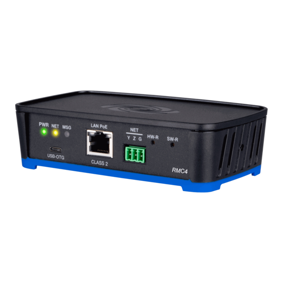
Page 10: Physical Description
Physical Description The RMC4 provides the following connectors and indicators. RMC4 Front Panel RMC4 Rear Panel Connectors USB-OTG (1) USB Type Micro-AB female; USB OTG port for computer console and USB mass storage devices LAN PoE (1) 8-pin RJ-45 connector, female; 100BASE-T Ethernet port;... - Page 11 DIGITAL IN 1–2 (1) 3-pin 3.5 mm detachable terminal block; Comprises (2) digital inputs (referenced to GND); Voltage Range: Rated for 0–24VDC; Input Impedance: 2.2k Ω pulled up to 5V; Logic Threshold: >2.0V low/0 and <1.1V high/1 RELAY 1–2 (1) 4-pin 3.5 mm detachable terminal block; Comprises (2) normally open, isolated relays;...
-
Page 12: Specifications
Specifications Product specifications for the RMC4 are provided below. Product Specifications Control Engine Crestron® 4-Series™; real-time, preemptive multi-threaded/multitasking kernel; Transaction-Safe Extended FAT file system; supports up to 10 simultaneously running programs (license required ), native .AV Framework™ software program Communications Ethernet 100 Mbps, auto-switching, auto-negotiating, auto-discovery, full/half duplex,... - Page 13 DIGITAL IN 1–2 (1) 3-pin 3.5 mm detachable terminal block; Comprises (2) digital inputs (referenced to GND); Voltage Range: Rated for 0–24VDC; Input Impedance: 2.2k Ω pulled up to 5V; Logic Threshold: >2.0V low/0 and <1.1V high/1 RELAY 1–2 (1) 4-pin 3.5 mm detachable terminal block; Comprises (2) normally open, isolated relays;...
- Page 14 "Request for SW-RMC3-10PROG License” form. For questions, contact license@crestron.com. 2. The NET (Cresnet) port on the RMC4 is a 3-pin connector which provides connectivity (and not power) for Cresnet data only. The Cresnet power conductor does not terminate to the RMC4. An external Cresnet power supply is required to provide power for Cresnet devices.
-
Page 15: Dimension Drawings
4. This feature is only available when using the TSR-310. Other Crestron touch screens, handheld remotes, and keypads are not supported. For these interfaces, traditional IR or CEC control must be used to control supported Apple devices. Dimension Drawings Add dimension drawings. -
Page 16: Installation
Installation Use the following procedures to install the RMC4 control system. Mount the Control System The RMC4 can be mounted onto a flat surface or a standard DIN rail using the included mounting bracket. CAUTION: To prevent overheating, do not operate the RMC4 in an area that exceeds the environmental temperature range (32 to 104°F or 0 to 40°C) for this device. -
Page 17: Din Rail Mounting
5. (Optional) Secure the RMC4 to the bracket using the two included 6-32 x 3/8 in. screws as shown in the following illustration. DIN Rail Mounting 1. Detach the RMC4 from the mounting bracket by pulling the left and right flanges of the bracket outward to release the tabs that hold the RMC4 in place. 2. -
Page 18: Connect The Control System
NOTE: Do not use the included screws to secure the bracket to the bottom of the RMC4 when mounting into a DIN rail, as it will then not be possible to remove the RMC4 from the DIN rail. Connect the Control System Make all device connections as shown in the following illustrations. - Page 19 Rear Panel Connections Observe the following when connecting the RMC4: Power is provided to the RMC4 by a single Ethernet cable. A Crestron PoE (Power over Ethernet) power supply, such as the PWE-4803RU, or a PoE-capable network switch is recommended (both not included).
-
Page 20: Configure The Control System
IP address. 1. Connect the control system to the network. 2. Use the Device Discovery tool in Crestron Toolbox™ software to discover the control system and its IP address on the network. 3. Enter the control system IP address into a web browser. -
Page 21: Create An Admin Account
The time zone must be set on the control system to ensure that the correct time settings are pushed to controlled devices. To set the time zone: 1. Access the web configuration interface using either the device IP address or the Crestron XiO Cloud service. 2. Navigate to Settings > System Setup. -
Page 22: Pair With Apple Homekit
The control system provides native support for the .AV Framework™ software program. .AV Framework software is a web-based management solution that is used to deploy scalable Crestron® enterprise room solutions without requiring any programming. For more information on the capabilities supported by .AV Framework, visit www.crestron.com/avframework. -
Page 23: Configuration
Connect to XiO Cloud Service. To access the configuration interface: 1. Use the Device Discovery tool in Crestron Toolbox™ software to discover the control system and its IP address on the network. 2. Open a web browser. 3. Enter the control system IP address into the browser URL field. A login page is displayed. -
Page 24: Actions Menu
The configuration interface provides the following tabs: Status: Used to monitor control system status Settings: Used to configure control system settings Security: Used to configure authentication and other security settings 802.1x Configuration: Used to configure IEEE 802.1x network authentication for control system security The Status tab is the default tab that is displayed, as shown in the preceding image. Actions Menu The configuration interface provides an Actions drop-down menu on the top right of the page. -
Page 25: Reboot
Firmware Upgrade Dialog Box To upload a firmware PUF through the web configuration interface: NOTE: Visit the appropriate device product page or www.crestron.com/Support/Resource- Library to download the latest firmware PUF. 1. Select Browse, and then navigate to the firmware PUF on the host computer. -
Page 26: Manage Certificates
Manage Certificates Select Manage Certificates to manage any certificates that are installed on the control system. For more information on certificate management, refer to 802.1x Configuration (on page 52). Status Select the Status tab on the top left of the configuration interface to display selections for viewing the status of device, network, and USB, and .AV Framework™... -
Page 27: Network
Network Select Network to view the status of the network settings for the control system. Status Tab - Network The following Network information is displayed: Hostname: The control system hostname Domain Name: The control system domain name NIC 1 DNS Servers: The DNS (domain name server) addresses used to resolve the control system domain to an IP address Select the + (plus) icon next to Adapter 1 to display the following Ethernet settings: DHCP: Reports whether the IP address is dynamic (Yes) or static (No) -
Page 28: Program
Link Active: Reports the status of the Ethernet connection (A true message indicates that the Ethernet connection is active, while a false message indicates that the Ethernet connection is inactive.) MAC Address: The unique MAC (media access control) address for the Ethernet adapter Program Select Program to view the status of the program and slave mode settings for the control system. -
Page 29: Av Framework
AV Framework Select AV Framework to view the status of the native .AV Framework software program running on the control system Status Tab - AV Framework The following AV Framework information is displayed: AV Framework: Reports whether the native .AV Framework software program has been turned on (Enabled) or not (Disabled) AV Framework Version: Reports the version of the native .AV Framework software program running on the control system, shown only if the native .AV Framework software program is turned on... -
Page 30: System Setup
NOTE: If an invalid value is entered for a setting, the web interface will not allow changes to be saved until a valid value is entered. Red text is displayed next a setting to indicate an invalid value. System Setup Select System Settings to configure general network and control system settings. - Page 31 Time/Date Select the + (plus) icon next to Time/Date to display the following time and date settings. Settings Tab - System Setup (Time/Date) Time Synchronization: Turn on the toggle to use time synchronization via NTP (Network Time Protocol). Synchronize Now: With Time Synchronization turned on, select Synchronize Now to synchronize the control system with the NTP server(s) entered in the NTP Time Servers table.
- Page 32 NTP Time Servers: With Time Synchronization turned on, use the provided table to enter information regarding the NTP server(s) used to synchronize the date and time for the control system. Select Add to add a new NTP server entry into the table. Enter the following information for each entry: Enter the NTP server address into the Address text field.
- Page 33 Network Select the + (plus) icon next to Network to display the following network settings. Settings Tab - System Setup (Network) Hostname: Enter the control system hostname. Domain: Enter the fully qualified domain name on the network. Primary Static DNS: Enter the primary DNS address. Secondary Static DNS: Enter the secondary DNS address.
- Page 34 If Web Server Enabled is turned on, enter an HTTPS port to use for the web server in the HTTPS Port text field. Port 443 is used by default. Crestron Internet Protocol Select the + (plus) icon next to Crestron Internet Protocol to display the following Crestron Internet Protocol (CIP) port settings. Settings Tab - System Setup (Crestron Internet Protocol) Enter the Crestron Internet Protocol port used by the control system in the CIP Port text...
- Page 35 Select the + (plus) icon next to SSH to display the following SSH (Secure Shell) settings. Settings Tab - System Setup (SSH) Turn on the SSH Enabled toggle to turn on SSH for the control system. If SSH Enabled is turned on, enter a port to use for the SSH protocol in the SSH Port text field.
-
Page 36: Programs
Programs Select Programs to manage control system programs and to configure subordinate mode settings for the control system. Settings Tab - Programs Slave Mode NOTE: For more information on using subordinate mode for a 4-Series control system, refer to the "Master-Slave Mode" topic in the 4-Series Control Systems Reference Guide. - Page 37 Program Slot Management NOTE: For more information on managing programs on a 4-Series control system, refer to the "Program Management" topic in the 4-Series Control Systems Reference Guide. Select the + (plus) icon next to Program Slot Management to display the following program management settings.
- Page 38 Load a New Program To load a new program to the control system: 1. Select the Upload Program button in an available program slot. The Add Program dialog box is displayed. Add Program Dialog Box 2. If desired, fill the Do not copy IP Table check box to prevent the program IP table from being copied to the control system following the upload.
- Page 39 IP ID. Port #: Enter the port used for communication between device and control system. Room Id: Enter the Crestron Virtual Control (VC-4) room ID that is associated with the IP table entry. This setting is applicable only for VC-4 connections.
-
Page 40: Projects
Projects Select Projects to manage web and mobility projects for the control system. Settings Tab - Programs Each loaded project is represented in a table that provides the following information and controls: Projects: The project number on the control system Name: The name for the web or mobility project Mobility: Displays a green check icon if the project is a mobility project Web Project: Displays a green check icon if the project is a web project Actions: Select the trash can button... - Page 41 3. Select the Project File button. The File Upload dialog box is displayed. File Upload Dialog Box 4. Select Browse, and then navigate to the project file on the host computer. 5. Select the project file, and then select Open. 6. Select Load to load the project file to the control system. The upload progress is shown in the dialog box.
-
Page 42: Services
Crestron Fusion 10 On-Premises Software Getting Started Guide. Turn on the Crestron Fusion Cloud toggle to allow a connection to a Crestron Fusion Cloud server. If Crestron Fusion Cloud is turned on, enter the address used to connect the control system to the desired Crestron Fusion Cloud server in the Crestron Fusion Cloud URL text... -
Page 43: Cloud Settings
Apple HomeKit NOTE: For more information on pairing the device with an Apple® HomeKit® system, refer to support.apple.com/en-us/HT204893. Turn on the Apple Home Kit toggle to turn on the HomeKit feature on the control system. Cloud Settings Select Cloud Settings to turn a connection between the control system and an XiO Cloud® service account on or off. -
Page 44: Auto Update
Auto Update Select Auto Update to configure automatic firmware updates for the control system and connected devices. Settings Tab - Auto Update NOTE: For more information on configuring automatic updates for the control system, refer to the "Auto Update Mechanism" topic in the 4-Series Control Systems Reference Guide. - Page 45 Enter a password for accessing the auto update server in the Password text field. Crestron Devices The following settings can be configured for updating connected Crestron devices if Auto Update is turned on: Enter a username for pushing automatic updates to controlled Crestron devices in the Username text field.
-
Page 46: Av Framework
AV Framework Select AV Framework to configure the native .AV Framework software program running on the control system. Settings Tab - AV Framework NOTE: If an older version of the .AV Framework program is detected in the Program 01 slot (6.13 and prior), the program is loaded to the Program 00 slot, but it is not turned on within the control system. -
Page 47: Security
Security Select the Security tab on the top left of the configuration interface to display selections for configuring security and authentication settings for the control system. Security Tab Selections Expand the Security accordion to configure the following settings: NOTE: For more information about configuring authentication settings on a 4-Series control system, refer to the "Authentication" topic in the 4-Series Control Systems Reference Guide. -
Page 48: Current User
Control system users and groups can be viewed and modified within the table provided at the bottom of the accordion. Use the following settings to add, delete, and edit control system users and groups. Current User Select the Current User tab to view and edit information for the current control system user. Current User Tab The following settings are displayed for the current user: Name: The chosen username... -
Page 49: Users
Change Password Dialog Box Enter the existing password in the Current Password field. Then, enter a new password in the Password field, and reenter the password in the Confirm Password field. Select OK to save the new password, or select Cancel to cancel the change. Users Select the Users tab to view and edit information for the control system users. - Page 50 NOTE: A user must be added to an Active Directory group before the user may be selected as an active directory user. For more information, refer to Groups (on page 49). If the control system users span multiple pages, use the navigation arrows on the bottom of the page to move forward or backward through the pages, or select a page number to navigate to that page.
- Page 51 Update User Dialog Box The following Update User settings may be viewed or configured: Name: The chosen username Active Directory User: Turn on the toggle to use authentication via Active Directory for the selected user. Password: Enter a new password for the selected user. Confirm Password: Reenter the password provided in the Password field.
- Page 52 Create User Dialog Box Use the following settings to create a new user: Name: Enter a username. Active Directory User: Turn on the toggle to use authentication via Active Directory for the user. Password: Enter a password for the user. Confirm Password: Reenter the password provided in the Password field.
-
Page 53: Groups
Groups Select the Groups tab to view and edit settings for control system groups. Control system groups are used to group users by access level and Active Directory authentication settings. Groups Tab Enter text in the Search Groups field to find and display groups that match the search term(s). Control system groups are listed in table format. - Page 54 Active Directory group in the Name field. If this information is being entered via console commands, omit domain\local from the command (for example, adddomaing -n:crestron -L:A instead of adddomaing - n:domain.local\crestron -L:A). Access Level: The access level of the group and its users...
- Page 55 Create Group Dialog Box Use the following settings to create a new group: Name: Enter a group name. Access Level: Select an access level for the group and its users from the drop-down menu. Active Directory Group: Turn on the toggle to use authentication via Active Directory for the group.
-
Page 56: 802.1X Configuration
802.1x Configuration Select the 802.1x Configuration tab on the top left of the configuration interface to display selections for configuring IEEE 802.1X network authentication for control system security. 802.1x Configuration Tab Selections Expand the 802.1x Configuration accordion to configure the following settings: NOTE: For more information about configuring 802.1X network authentication on a 4-Series control system, refer to the "802.1X" topic in the 4-Series Control Systems Reference... - Page 57 Authentication Method: Select an 802.1 authentication method (EAP-TLS Certificate or EAP MSCHAP V2- password) from the drop-down menu. Domain: If EAP MSCHAP V2- password is selected for Authentication Method, enter a domain name that is required for authentication. Username: If EAP MSCHAP V2- password is selected for Authentication Method, enter a username that is required for authentication.
- Page 58 Type a search term into the Search… text field to search for and display CAs that match the search term. The following information is provided for each type of CA: Name: The CA name Expiry Date: The date and time that the CA is set to expire If the CAs span multiple pages, use the navigation arrows on the bottom of the page to move forward or backward through the pages, or select a page number to navigate to that page.
-
Page 59: Programming
Programming 4-Series control systems support an open development environment that enables programmers to use standard tools to create C# programs. Programmers can also use Crestron tools such as SIMPL, SIMPL# Pro, and VT Pro-e® software to create control system programs and projects. -
Page 60: Resources
Resources The following resources are provided for the RMC4. NOTE: You may need to provide your Crestron.com web account credentials when prompted to access some of the following resources. Crestron Support and Training Crestron True Blue Support Crestron Resource Library Crestron Online Help (OLH) Crestron Training Institute (CTI) Portal... - Page 61 This page is intentionally left blank. Product Manual — Doc. 9227A RMC4 • 57...
- Page 62 Product Manual — Doc. 9227A Crestron Electronics, Inc. 15 Volvo Drive, Rockleigh, NJ 07647 01/31/22 Tel: 888.CRESTRON Specifications subject to Fax: 201.767.7656 change without notice. www.crestron.com...