Crestron 4 Series Product Manual
Lighting control system
Hide thumbs
Also See for 4 Series:
- Product manual (72 pages) ,
- Quick start manual (12 pages) ,
- Quick start (5 pages)

Related Manuals for Crestron 4 Series


Summary of Contents for Crestron 4 Series
- Page 1 ZUM-HUB4 4-Series™ Control Processor for Zūm® Lighting Control System Product Manual Crestron Electronics, Inc.
- Page 2 United States and/or other countries. Other trademarks, registered trademarks, and trade names may be used in this document to refer to either the entities claiming the marks and names or their products. Crestron disclaims any proprietary interest in the marks and names of others. Crestron is not responsible for errors in typography or photography.
-
Page 3: Table Of Contents
Features Zūm Net Wired Technology Web-Based Management Time Clock BACnet™ Communications Protocol Crestron XiO Cloud® Service Integration Zūm Wireless Integration Zūm System Integration with Other Crestron Control Systems Physical Description Specifications Product Specifications Dimension Drawings Installation Mount to a Rack... - Page 4 Manage Settings Manage Users Manage External Controls Manage Commissioning Review Device Information and Status Reboot ZUM-HUB4 ii • Contents Product Manual — Doc. 9094B...
- Page 5 iii • Contents Product Manual — Doc. 9094B...
-
Page 6: Overview
The device provides a web-based user interface for control. A built-in time clock enables room lighting and occupancy and vacancy sensing automation. The ZUM-HUB4 can also be integrated with other Crestron lighting systems and control systems. The ZUM-HUB4 is featured in three kits. -
Page 7: Features
BACnet™ communication supports control for up to 9,000 BACnet objects Dedicated Control Subnet Gigabit Ethernet networking Enterprise-grade security Enables integration with other Crestron lighting systems, control systems, touch screens, shading, HVAC, and more Single-space rack-mountable Universal 100–240V external power supply Zūm Net Wired Technology... -
Page 8: Bacnet™ Communications Protocol
Mirrored Rooms: An external Crestron system controls and monitors a room equipped with a Zūm system. Mirrored rooms allow for room control with a Crestron touch screen or handheld remote, as well as integration with shading, climate control, AV, and other equipment. -
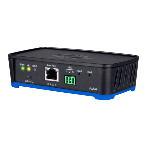
Page 9: Physical Description
Physical Description Connectors and Card Slots MEMORY (1) SD memory card slot; Accepts one 32 GB SD or SDHC card to enable logging and for troubleshooting purposes (1) USB Type A connector, female; USB 2.0 host port (not used) (1) 8-pin RJ-45 connector, female; 10Base-T/100Base-TX/1000Base-T Ethernet port;... - Page 10 (1) Green LED; Indicates operating power supplied from the included power pack (1) Amber LED; Not used (1) Red LED; Indicates that the ZUM-HUB4 has generated an error message HW-R (1) Recessed pushbutton for hardware reset SW-R (1) Recessed pushbutton for software reset LAN (rear) (2) Bi-color green/amber LEDs;...
-
Page 11: Specifications
Specifications ZUM-HUB4 specifications for device support and time clock, communications, connectors and card slots, controls and indicators, power, environmental, dimensions, weight, and compliance certifications. • Product Specifications • Dimension Drawings Product Specifications Device Support and Time Clock Rooms 1,000 maximum; Zūm wired, Zūm wireless, and external External Rooms and Varies by control system based on hardware capabilities and program... - Page 12 (1) 4-pin 3.5 mm detachable terminal block; (24 Y Z G) Connects to a GLS-SIM which facilitate Demand Response when connected to a non-system sensor, such as a GLS-ODT-C-NS; Not used for power 24VDC 2.0A (1) 2.1 x 5.5 mm DC power connector; 24VDC power input;...
- Page 13 UL® Listed for US & Canada, IC, CE, FCC Part 15 Class B digital device, UL 916, CEC Title 24, ASHRAE 90.1, IECC NOTES: SIMPL+® software modules are provided for use in commissioning a Crestron control system to work with the ZUM-HUB4. The software modules run within the control system program and provide virtual connections for all the necessary intersystem control signals.
- Page 14 Dimension Drawings Product Manual — Doc. 9094B ZUM-HUB4 • 9...
-
Page 15: Installation
Make Connections The ZUM-HUB4 has a dedicated Control Subnet that is used for communication between the control system and Crestron Ethernet devices. This subnet allows for dedicated communication between the control system and Crestron Ethernet devices without interferences from other 10 •... - Page 16 The ZUM-HUB4 can be powered with the (included) 24VDC power pack. Do not connect the CONTROL SUBNET port to the LAN. The CONTROL SUBNET port must be connected only to Crestron Ethernet devices. For details on using the Control Subnet, refer to the 4-Series™...
- Page 17 Zūm Wired System Diagram NOTES: Daisy-chain up to 20 Zūm Net devices (up to a maximum of 328 ft (100 m) per leg) with purple CBL-CAT5E-ZUMNET-P RJ-45 cables (sold separately). System sensors communicate digitally via Zūm Link. Non-system sensors communicate via an analog connection on a Zūm Wired J-BOX. 12 •...
-
Page 18: Configuration
Configuration Before using the ZUM-HUB4, ensure it is updated with the latest firmware. Refer to Version Management (on page 55). Once all of the devices are installed in the space and using the latest firmware, use the Zūm app to modify default behavior. Expedite commissioning by copying a room configuration and sending it to an identical room. - Page 19 14 • ZUM-HUB4 Product Manual — Doc. 9094B...
- Page 20 1. Room Settings: Edit the Room Name, PIN, Floor ID, Zone ID, and Network information. 2. Configuration: Edit the room logic view the current state of the room. Sensors: View details for the connected sensor(s). Edit sensor name. Load Controllers: Identify and view the details for the connected load controller(s). ZUMLINK-JBOX-16A-LV and ZUMNET-JBOX-16A-LV load controllers: View Current Scene, Daylighting status, Output Level.
- Page 21 Keypads: Identify and view the details for the connected keypad(s). Edit the keypad name and assign the button layout. Adjust the Double Tap Speed: Set the amount of time between two button presses to qualify as a double tap. Specify the Button Layout and click on a button to configure button actions. Button action options: None Off: Assigned load controllers turn off.
- Page 22 Tap and slide a device from right to left until the blue Edit button appears. Use the edit screen to change the name of the device and the name of the device functions. Also, identify or edit the connected devices. 4.
-
Page 23: Calibrate Daylighting Settings
5. Configuration Data: Save room configuration: Save the room configuration data in the space. Send configuration to room: Send room logic changes made in the app to the room. Advanced data management: Review the Map, Logic, and Settings of the data currently loaded. - Page 24 To calibrate the daylight settings: 1. Assign the photocell component to the load controller that will participate in Daylighting. a. From the Main screen, click Configuration. b. Click Load Controllers. c. Click the desired load controller. d. For Photo, select a photocell from the drop-down menu. Product Manual —...
- Page 25 2. Send the configuration to the room. a. Navigate back to the Main screen. b. Click Send configuration to room. A confirmation window opens stating that the app will disconnect from the room. Click OK to continue or Cancel to close without sending the configuration. The Retrieving Data Map screen displays.
- Page 26 3. Recall Scene 1 and adjust load levels. a. From the Main screen, click Configuration. b. Click Scenes. c. Select Scene 1. Daylighting is only available for Scene 1. d. Adjust the loads in the space to the appropriate level based on the amount of natural light.
-
Page 27: Log Into The Web-Interface
c. Click Daylight Properties. d. Click Calibrate Daylighting. To indicate that Daylighting has been calibrated, the lights in the space will turn full on, turn off, and then back on with the Daylighting settings. Whenever Scene 1 is recalled, the Daylighting settings are initiated. Log into the Web-Interface The ZUM-HUB4 is configured using the web interface. -
Page 28: Web Interface Overview
Web Interface Overview The web interface gives users the ability to configure room behavior globally across the ZUM-HUB4, by Room Category, by Floor, and by Room. Product Manual — Doc. 9094B ZUM-HUB4 • 23... -
Page 29: Category View, System View, And Settings View
Category View, System View, and Settings View The web interface has three configuration sections: Category View to manage Rooms, System View to manage Floors and devices, and Settings View to manage settings. Category View The Category View lists room categories and rooms (in the Rooms tab) that have been discovered by the ZUM-HUB4. -
Page 30: Global Settings And Actions For The Zum-Hub4
System View The System View lists Floors and rooms (in the Rooms tab) that are discovered by the ZUM-HUB4. Use the Hardware Management tab to view and edit device information, such as assigning a device to a floor. Manage Floors (on page 49) Set the Bluetooth PIN for a Floor (on page 32) Set the Demand Response Level for a Floor (on page 36) Manage Devices (on page 50) -
Page 31: Navigation Toggle
Navigation Toggle Click to collapse or the Category View, System View, Setting Views, and the global ZUM-HUB4 settings. Device Information and Status View the Demand Response status, system alerts, help information, or sign out of the web interface. Refer to Review Device Information and Status (on page 66). -
Page 32: Discover Rooms
• Review Device Information and Status • Reboot ZUM-HUB4 Related topics: Zūm App Configuration (on page 13) Log into the Web-Interface (on page 22) Discover Rooms To discover rooms: 1. Click the Actions menu 2. Click Discover. The Discover window opens. 3. Select the type of rooms you want to discover. 4. -
Page 33: Add A Room Category
Add a Room Category To create a room category: 1. Click the menu beside the ZUM-HUB4. 2. Click Add Category. 3. Type the name of the Room Category. 4. Click to save the Room Category or to cancel. For more information about Room Categories, refer to Manage Room Categories. - Page 34 This section provides the following information: Turn On/Off All Discovered Devices (below) Turn On/Off a Room Category (below) Turn On/Off a Floor (below) Turn On/Off a Room (on the next page) Turn On/Off All Discovered Devices To turn all devices on/off: 1.
-
Page 35: Set The Bluetooth Pin
3. Click All Off or All On. Turn On/Off a Room You can turn a specific room on/off using the Control Room window, but this option provides more detailed settings. Refer to Control a Room (on page 40). Set the Bluetooth PIN The Bluetooth PIN enables a mobile device with the Zūm app to connect to the Zūm Wired Keypad or the Zūm Network Bridge. - Page 36 Set the Bluetooth PIN for a Room Category To set the Bluetooth PIN for devices in a Room Category: 1. Open the Category View. 2. Click the menu beside the Room Category name. 3. Click Bluetooth PIN. 4. Set the PIN (0 to 9999). 5.
- Page 37 1. Open the Category View and the Room tab. 2. Click the to open the Control Room window. 3. For Bluetooth PIN, set the PIN (0 to 9999). 4. Click Send to send changes to the room, or close the Control Room window to discard unsaved changes.
-
Page 38: Configure The Demand Response Mode And Level
Configure the Demand Response Mode and Level The Demand Response Level is used in emergency situations to override the current load settings in the room. The load levels reduce when a demand response command is received from the utility company. Demand Response Mode can be manually controlled by accessing the Actions Menu. - Page 39 3. Click the toggle turn Demand Response Mode on or off. If a GLS-SIM has been discovered by the ZUM-HUB4, the GLS-SIM status is represented as Offline or Online. 4. Click Save to save the settings or Cancel to close the window without saving. Set the Demand Response Level for All Discovered Devices To set the Demand Response Level for all devices: 1.
- Page 40 4. Set the light level (0 to 100). 5. Click to save or to cancel. Set the Demand Response Level for a Room To set the Demand Response Level for devices in a Room: 1. Open the Category View and the Room tab. 2.
- Page 41 Set the Demand Response Level for a Floor To set the Demand Response Level for devices on a Floor: 1. Open the System View. 2. Click the menu beside the Floor name. 3. Click Demand Response Level. 4. Set the light level (0 to 100). 5.
-
Page 42: Manage Rooms
Manage Rooms The Rooms tabs lists the Rooms discovered by the ZUM-HUB4 or the rooms assigned to a selected Room Category. Use the Rooms tab search for a room, delete rooms, reassign room categories, edit a room name, view room details, or control a room. Access the Rooms tab through either the Category View or the System View tabs. - Page 43 Occ: Identifies a room with an Occupancy Sensor. The Occupancy sensor symbols ( ) displays when occupancy is detected. Active Scene: Displays the current Scene. Next Event: Displays the upcoming event. Information ( ): Displays room details. Hostname: Displays the Hostname. Room Type: Wired, Wireless, or External room ID: Displays the IP ID for a Wired room, the RF ID for a Wireless room, and the Module ID for an External room...
- Page 44 Find a Room on the ZUM-HUB4 For a ZUM-HUB4 that has a large number of rooms, use the search feature to find a room name. To search for a room: 1. Click on the ZUM-HUB4 or on a Room Category. 2.
- Page 45 4. A confirmation dialog opens. Click Yes to add the room(s) the Room Category or No to cancel. Control a Room Open the Control Room window to select a Lighting Scene, change the state of Plug Loads, enable or disable the occupancy sensor, set the Bluetooth PIN, or set the Demand Response level for a specific room.
-
Page 46: Schedule Room Behavior
Occupancy Sensor To enable or temporarily disable occupancy sensing: 1. Click the toggle to enable or temporarily disable occupancy sensing. When disabling occupancy sensing, set the amount of time the occupancy sensor is disabled. The sensor may be disabled for up to 1,415 minutes or appropriately 23 hours. 2. - Page 47 3. Click the desired date in the calendar. If necessary, change the month and year using the drop-down menus, and then click the desired date. A menu displays a list of the available Day Patterns. 4. Select the desired Day Pattern. Day Patterns A Day Pattern consists of various Room States that are assigned throughout the day.
- Page 48 Add Day Patterns Click Add Day Pattern and enter the desired Day Pattern name. Click to save the name, click to cancel. Delete Day Pattern To delete a Day Pattern: 1. Click to delete a Day Pattern. A Confirmation window opens. 2.
- Page 49 Room State Schedule Use the Room State Schedule window to modify the pattern of Room States in each Category for the selected Day Pattern. To add a Room State to a Room Category: 1. Click to add a Room State. The Add Room State window opens. 2.
- Page 50 To edit a default or custom event block: Change the assigned Room State: 1. Click an event block, and a dialog opens. 2. Click and choose a new Room State from the drop-down menu. 3. Click Ok to save the changes or Cancel to close the window without saving. Change the assigned time: Click and drag the event block to the desired time within the time table.
- Page 51 Room States A Room State is both a set of events as well as a set of behaviors for a Room Category. It identifies the lighting scene that is recalled, the functionality of the occupancy sensor and the plug load controllers. To access the Room States menu, click the Schedule tab and click expand the scheduling menus.
- Page 52 Configure a Room State Click Add Room State to add a new Room state or to edit an existing Room State. The Room State Settings window opens. To configure a Room State in the Room State Settings window: 1. Enter or edit the name of the desired Room State in the Room State Name filed. 2.
- Page 53 Holidays The Holidays menu allows you to create a new holiday and to edit the holiday properties. Holidays that are enabled are automatically added to the calendar in the Schedule tab. To access the Holidays menu, click the Schedule tab and click to expand the scheduling menus.
-
Page 54: Manage Floors
Configure Holidays After adding a Holiday, the Holiday Settings window opens. Alternatively, clicking beside a Holiday opens the Edit Holiday Settings window. These windows display the Holiday settings. To configure Holidays in the Holiday Settings window: 1. Enter or edit the name of the desired Holiday in the Holiday field. 2. -
Page 55: Manage Devices
Manage Devices In the System View, manage devices in the Hardware Management tab. Devices are divided into two categories: Wired and Wireless. Expand the Wireless menu to view and edit wireless devices. Expand the Wired menu to view and edit wired devices. Rooms must be discovered by the ZUM-HUB4 before performing any procedure in this section. - Page 56 Assign a Floor ID to a Gateway Assigning a Floor ID to a gateway helps gateways discover wireless devices with the matching Floor ID. Set a device's Floor ID in the Zūm app before discovering the devices on the ZUM-HUB4. The Floor ID drop-down menu options are numbers -40 to + 200 and Disabled. The Floor ID can be negative to indicate a floor below ground or positive to indicate a level above ground.
- Page 57 Action: Move a room to a different gateway or remove a room. Click to move a room. The Move window opens. Select the desired gateway from the drop-down menu. Click Move to move the room or Cancel to close the window without moving the room.
- Page 58 Assign a Floor ID to an RAP Assigning a Floor ID to a load controller adds a floor to the Floor list. The Floor ID drop-down menu options are numbers -40 to + 200 and Disabled. The Floor ID can be negative to indicate a floor below ground or positive to indicate a level above ground.
- Page 59 Status: Displays Online or Offline to show the component's status. Manage Settings Access Settings in the Settings View. The Settings tab displays and allows you to edit the firmware, system time and location, network configuration, security configuration, and Crestron services. 54 • ZUM-HUB4...
- Page 60 Version Management Allows you to check for firmware updates for the ZUM-HUB4 and connected devices. Firmware updates for battery powered devices may take up to 24 hours. To update firmware: 1. Open Settings View. 2. Click Settings. 3. Click Version Management. 4.
- Page 61 Location Displays the location (latitude and longitude). Accurate location ensures the Sunrise/Sunset Schedule displays the correct sunrise and sunset times. To change the location: 1. Open Settings View. 2. Click Settings. 3. Click Location. 4. Enter new values in the fields. 5.
- Page 62 Security Configuration Allows the user to change the device service password. To edit the password: 1. Open Settings View. 2. Click Settings. 3. Click Security Configuration. 4. Click and to new values in the fields. 5. Click to save the changes or to discard changes.
- Page 63 Manage Users Access Users in the Settings View. The Users tab shows a list of all users and allows you to create new users and modify or delete existing users. The username must be 3 to 15 characters and are permitted to use uppercase letters (A-Z, lowercase letters (a-z), digits (0-9), and special characters (- ( ) + [ ] .
- Page 64 SIMPL+® software module. NOTES: SIMPL+® software modules are provided for use in commissioning a Crestron control system to work with the ZUM-HUB4. The software modules run within the control system program and provide virtual connections for all the necessary intersystem control signals.
- Page 65 User for External Rooms. SIMPL+® software modules are provided for use in commissioning a Crestron control system to work with the ZUM-HUB4. The software modules run within the control system program and provide virtual connections for all the necessary intersystem control signals. A separate dedicated module is required for each external and mirrored room.
- Page 66 Add Macro To add a new macro: 1. Open Settings View. 2. Click the External Controls tab and expand the External Controls menu. 3. Click . A new row appears. 4. Configure the macros settings: Enter the Export ID. Enter the Macro Name. Select a Room State.
- Page 67 3. Configure the BACnet settings: NOTE: Use the search to find a specific room. BACnet Service: Click the toggle to turn the BACnet service on or off. Host ID: The ID that the ZUM-HUB4 uses when communicating with the BACnet system.
- Page 68 Manage Commissioning Access Commissioning in the Settings View. Use the Commissioning tab to manage, map, and deploy, room templates. To create a new template, use the Zūm app. Template Management Upload a new template or search, extract, edit, or delete an existing template. Add a New Template To add a new room template: 1.
- Page 69 Edit Template Name To edit an existing template name: 1. Open Settings View. 2. Click the Commissioning tab and expand the Template Management menu. 3. If necessary, use the Search bar to find a room template. 4. Click 5. Type the new name. 6.
- Page 70 Apply and Deploy Templates. To apply and deploy a template: 1. Open Settings View. 2. Click the Commissioning tab and expand the Mapping and Template Deployment menu. 3. Select a room or multiple rooms. If necessary, use the Search bar to find a room. 4.
- Page 71 Review Device Information and Status View the Demand Response status, system alerts, help information, or sign out of the web interface. Demand Response Status Demand Response is enabled. Demand Response is disabled. System Information Displays system alerts. Help Click to view the help file. 66 •...
- Page 72 Sign Out Click to bring up the Sign Out pop-up. Click Sign Out to log out of the ZUM-HUB4. Reboot ZUM-HUB4 To reboot the ZUM-HUB4: 1. Click the Actions menu 2. Click Reboot. The Confirmation window opens. 3. Click Yes to Reboot or No to close the window without rebooting. Product Manual —...
- Page 73 This page is intentionally left blank. Product Manual — Doc. 9094B ZUM-HUB4 • 68...
- Page 74 Product Manual — Doc. 9094B Crestron Electronics, Inc. (2055411) 15 Volvo Drive, Rockleigh, NJ 07647 11/18/21 Tel: 888.CRESTRON Specifications subject to Fax: 201.767.7656 change without notice. www.crestron.com...