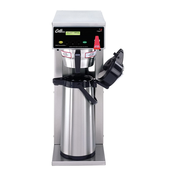
Curtis G3 User Manual
Digital combo brewers
Hide thumbs
Also See for G3:
- User manual (60 pages) ,
- Specification sheet (4 pages) ,
- Brochure & specs (4 pages)

Related Manuals for Curtis G3


Summary of Contents for Curtis G3
- Page 1 USER GUIDE G3 Digital Combo Brewers Style varies with model READ AND SAVE THESE INSTRUCTIONS NOTICE TO INSTALLER: Please leave this booklet with the machine.
-
Page 2: Table Of Contents
....................FS15 ............................... IS2 ........................IS15 ..........................II2 ..................II8 ............................OI12 ..........................CI1 ....................CI9 ........................CI6 ....................................................................................................IP15 ................. IP21 ..............IP22 ..............IP23 ......................................ES18 .........................ES19 ......................................................................................................................................Contact Information Wilbur Curtis Co., Inc. . PT... -
Page 3: Fs15
• Multiple Beverage Options – Allows you to brew Coffee, Iced Coffee and Iced Tea from one model. • Generation Three (G3) Digital Control Module – Offers full brewing programmability with unsurpassed standard features. • adjust time, volume, temperature, brew functions and more. -
Page 4: Is2
INSTRUCTIONS could result in personal injury or void the warranty. • This appliance is designed for commercial use. Any service other than cleaning and preventive maintenance should be performed by an authorized Wilbur Curtis service technician. • serviceable parts inside. - Page 5 IMPORTANT SAFEGUARDS CE Requirements • This appliance must be installed in locations where it can be overseen by trained personnel. • • This appliance is not suitable for outdoor use. • • • This appliance must not be cleaned by water jet. •...
-
Page 6: Is15
IMPORTANT SAFEGUARDS IS15 European Regulations and Directives • This appliance meets the requirements of all applicable regulations in Regulation 1907/2006/EU (REACH), Directive 2011/65/EU (ROHS) and its amendment (EU) 2015/863, Directive 2012/19/EU (WEEE), Directive 2014/30/EU (EMC), Directive 2006/42/EC (Annex I - IX) and Directive 2014/35/EU (LVD). •... -
Page 7: Ii2
INSTALLATION INSTRUCTIONS WARNING: WARNING: Improper electrical connection may result in an electric shock hazard or damage the unit. This appliance must be properly grounded. NOTICE: DO NOT connect this appliance to a hot water supply. The water inlet valve is not rated for hot water. -
Page 8: Ii8
INSTALLATION INSTRUCTIONS Installation Leveling WARNING: Use the leveling legs to level the brewer only. Do not use them to adjust brewer height. Do not extend them higher than necessary. Position the brewer on the countertop. Level it left to right and front to back by turning the bottom of the legs. - Page 9 INSTALLATION INSTRUCTIONS Connect the Brewer Wiring (cont.) 11 If the power cord will be connected directly to the junction box, connect the power cable wires to the terminals in the junction box. See the ELECTRICAL SCHEMATIC for the power supply requirements. WARNING: Turn off power to the junction box at the circuit breaker panel before connecting the power cable to the brewer.
- Page 10 INSTALLATION INSTRUCTIONS Power Up the Brewer (cont.) 16 Make sure that the circuit breaker supplying power to the unit is on. 17 Turn the toggle switch on the back of the brewer to the 18 When the water in the tank rises to the correct level, the heating elements will turn on automatically.
-
Page 11: Oi12
Do not remove the brew basket while “Brewing” appears on the display. WARNING - DO NOT refrigerate unused tea overnight for later consumption. The G3 Combo Brewer is factory preset for optimal performance. DISPENSER The brewer should be ON. -
Page 12: Ci1
CLEANING INSTRUCTIONS WARNING: HOT SURFACES - To avoid injury, allow the brewer and dispenser(s) to cool before cleaning. NOTICE - Do not use cleaning liquids, compounds or powders containing chlorine (bleach) or corrosives. USE OF THESE PRODUCTS WILL VOID THE WARRANTY. Cleaning The Brewer - Daily WARNING: DO NOT immerse the brewer in water or any other liquid. -
Page 13: Ci9
CLEANING INSTRUCTIONS Cleaning the Airpot/Pour Pot (Daily) WARNING: DO NOT immerse the airpot/pour pot or lid assembly in water or any other liquid. Do not place the airpot/pour pot or lid in a dishwasher. Placing a airpot or pour pot in a dishwasher will void the warranty. Start by preparing a mild solution of detergent and warm water. -
Page 14: Ci6
CLEANING INSTRUCTIONS Cleaning the Tea Dispenser (Daily) Cleaning the Container Prepare a mild solution of detergent and warm water. Remove the dispenser from the brewer and remove the lid. Rinse. Wash - Wipe the exterior surfaces with a sponge and the detergent solution to remove spills and debris. - Page 15 PROGRAMMING GUIDE Curtis To enter programming mode: With unit OFF, press and hold bottom right BREW button (4). Then press and release Entering ON/OFF button. Continue to Programming mode hold down BREW button until Enter Code Enter Code appears. - - - - Enter 4 digit code.
- Page 16 PROGRAMMING GUIDE Programming Options To exit, press until Exit appears on the display, then press Tea Recipes - sets the tea recipe. Press to access. Press to choose from standard-gray, standard- purple, Standard-Amber, Tropical-Gray, Tropical-Purple, 76/308-Gray or 76/308-Purple. Press to save and exit programming mode.
- Page 17 PROGRAMMING GUIDE Tea Half Batch - turns half batch On and Off. Once accessed ( ), press to toggle between On and Off. Press to save. Press to display the subsequent menu features. Tea Drip-Out - sets the Tea Drip-Out time. Drip-out allows additional time for tea to drain from the brew basket before “Brewing”...
- Page 18 PROGRAMMING GUIDE Coffee Pulse Brew (combo units only) - selects the Coffee Pulse Brew pattern (Pre-Infusion must be Off to press the BREW button for which Pulse Brew needs to be changed. Press to select the desired setting (see guidelines below for information on various settings). Press to save.
- Page 19 PROGRAMMING GUIDE Cold Brew Lock - adjusts the temperature at which the brewer will brew when a BREW button is pressed (Ready to brew appears on the display). This feature also adjusts the temperature at which the heating below the temperature setting. Once accessed ( ), press to select the desired setting.
- Page 20 ROUGH-IN DRAWINGS RD18 CB, CBS 22.77" 22.23" [57.8 cm] [56.5 cm] 9.11" 16.61" [23.1 cm] [42.2 cm] 34.20" [86.9 cm] 13.41" [34.1 cm] 9.61" 28.94" [24.4 cm] [73.5 cm] 23.43" [59.5 cm] 12.40" [31.5 cm] 11.68" 9.14" [29.7 cm] [23.2 cm] 10.00"...
- Page 21 ROUGH-IN DRAWINGS RD19 9.94" [25.3 cm] 7.53" [19.1 cm] 9.11" 16.61" [23.1 cm] [42.2 cm] 10.69" 29.38" [27.2 cm] [74.6 cm] 25.30" [64.3 cm] 9.04" [23.0 cm] 23.50" 4.00" [59.7 cm] 10.97" [10.2 cm] [27.9 cm] 25.70" [65.3 cm]...
-
Page 22: Ip15
ILLUSTRATED PARTS/RECOMMENDED PARTS IP15 CB, CBP, CBS Series - Main Chassis - Exploded View 10A** 10B** between models 35** *Water Tanks Assemblies: Domestic units, see section IP21 Canadian units, see section IP22 30** Export units, see section IP23 Dual Voltage units, see section IP24 Units equipped with 2 single inlet valves **Orientation varies with model and instead of dual inlet valve, shown above... - Page 23 CB, CBP, CBS Series - Main Chassis - Parts List ITEM # PART # DESCRIPTION ITEM # PART # DESCRIPTION COVER, TOP ALPGT/D500GT/D60GT TLP/TCTS/ WC-390162 LABEL, UCM OVERLAY CBP/CB CURTIS LOGO WC-58117 CBS/GEMSS KIT, HOT WATER FAUCET REPLACEMENT WC-37252 a,b,c,d,f WC-3503 LEG, 3/8”-16 STUD SCREW BUMPER ALPGT/D60GT/D500GT SUPPORT, DECK EXTENDED SS PTTD /SCPTTD LEG, 4”...
-
Page 24: Ip21
ILLUSTRATED PARTS/RECOMMENDED PARTS IP21 WC-6277/WC-75236[-20] - Tank Assembly WC-6277/WC-75236[-20] - Tank Assembly - Parts List ITEM # PART # DESCRIPTION ITEM # PART # DESCRIPTION TANK, COMPLETE 1600W 120V D500GT/TCTS/ WC-5528K* KIT, WATER LEVEL PROBE, SILICONE WC-6277 PTT/CBS KIT, PROBE, ASSY WATER LEVEL W/HEX FITTING, WC-5502-01* TANK, ASSY D500GT/H/TCTS/PTT3/ CBS W/WC- O-RING &... -
Page 25: Ip22
ILLUSTRATED PARTS/RECOMMENDED PARTS IP22 WC-6283 - Tank Assembly WC-6283 - Tank Assembly - Parts List ITEM # PART # DESCRIPTION ITEM # PART # DESCRIPTION TANK, ASSY D500GT/H/TCTS/PTT3/ CBS W/WC- 917 WC-1438-101* SENSOR, TEMPERATURE TANK WC-75236-20 HEATING ELEMENT GUARD, SHOCK/HEATING ELEMENT FOR SINGLE WC-4394* WC-6283 TANK, COMPLETE 1450W 120V D500GT... -
Page 26: Ip23
ILLUSTRATED PARTS/RECOMMENDED PARTS IP23 WC-6290-101 - Tank Assembly WC-6290-101 - Tank Assembly - Parts List ITEM # PART # DESCRIPTION ITEM # PART # DESCRIPTION TANK, ASSY D500GT/H/TCTS/PTT3/ CBS W/WC- 934- WC-1438-101* SENSOR, TEMPERATURE TANK WC-75236-35 101 ELEMENT GUARD, SHOCK/HEATING ELEMENT FOR SINGLE WC-4394* PTT3 /CBS/W/WC- 934-01ELEMENT TANK, COM- HEATING ELEMENT... - Page 27 ILLUSTRATED PARTS/RECOMMENDED PARTS IP24 WC-6282 - Tank Assembly WC-6282 - Tank Assembly - Parts List ITEM # PART # DESCRIPTION ITEM # PART # DESCRIPTION GUARD, SHOCK/HEATING ELEMENT FOR SINGLE WC-4394* TANK, ASSY DUAL VOLTAGE D500GT TCTS/PTT3/ HEATING ELEMENT WC-75236DV CBS/ W/(2)WC-904 THERMOSTAT, HI LIMIT HEATER CONTROL DPST WC-522*...
-
Page 28: Es18
ELECTRICAL SCHEMATICS ES18 CB - 120 Volts CBS-10, ELECTRICAL SCHEMATIC 091516NC... -
Page 29: Es19
ELECTRICAL SCHEMATICS ES19 CB - 220 to 240 Volts UCM Pin Assignments 16 Pin Connector NOT USED NOT USED DILUTION VALVE INLET VALVE BREW VALVE TRIAC GATE ELECTRICAL RATING TABLE TRIAC A2 # of Tank Element 230V L1 Voltage Amps Wa s Hertz # of Tank... - Page 30 ELECTRICAL SCHEMATICS ES20 CB - 120/220 Volts CBS-63, ELECTRICAL SCHEMATIC 091516NC...
- Page 31 TROUBLESHOOTING GUIDE WARNING: Electric Shock Hazard - Scald and Burn Hazard - IMPORTANT: always Valve Test Procedure ELECTRICAL SCHEMATIC Troubleshooting Guidelines ERROR CODES • • • Use this troubleshooting guide along with the appropriate ELECTRICAL SCHEMATIC. • Valve Test Procedure in either direction Water Not Hot Enough replace the temperature sensor...
- Page 32 TROUBLESHOOTING GUIDE During Brewing ELECTRICAL SCHEMATIC No Power - Display Not Lit Water Tank Does Not Fill Brewer Does Not Start When Brew Button is Pressed Brewing Brewing Sensor Error Message...
- Page 33 TROUBLESHOOTING GUIDE Water Tank Does Not Fill IMPORTANT: Coffee/Tea Too Strong Dispenser Not Filled To Normal Level During Brewing Dispenser Not Filled To Normal Level During Brewing SPECIFICATIONS sure that the spray head is correctly aligned and that the tubing is routed properly to allow for maximum water ELECTRICAL SCHEMATIC...
- Page 34 TROUBLESHOOTING GUIDE All Of The Time ELECTRICAL SCHEMATIC No Water/Tea Flows From Brewer During Brewing Water Tank Does Not Fill ELECTRICAL SCHEMATIC Low Water Flow Warning Water Level Error Message Water Level Error Message ERROR CODES SPECIFICATIONS...
- Page 35 If the UCM is operating normally, check for a false over-temp error caused by the temperature sensor. Check the resistance across the leads of the temperature sensor. If the resistance is less than 10 k when the water is cool, replace the temperature sensor. G3 BREWERS WITH TRIAC, TROUBLESHOOTING GUIDE 052919C...
- Page 36 ERROR CODES System Fault Messages An error message will appear on the screen in the event of a malfunction under the following conditions: ERROR MESSAGE WARNING DESCRIPTION CAUSE Water Level Error G3 BREWER, ERROR CODES 042017A...
- Page 37 Return Merchandise Authorization (RMA): All returned equipment must be properly re-packaged in the original carton and received by Curtis within 45 days following the issuance of a RMA. NO UNITS OR PARTS WILL BE ACCEPTED WITHOUT A RETURN MERCHANDISE AUTHORIZATION (RMA).