
Related Manuals for Toshiba NV Series


Summary of Contents for Toshiba NV Series
- Page 1 6F8C1583 Unified Controller nv series type1 light Communication Interface Module (CF622) Instruction Manual...
- Page 2 (2) No part of the contents of this manual may be reproduced without permission from TOSHIBA Corporation. (3) The contents of this manual are subject to change without notice.
- Page 3 Specific details are indicated near the symbol with pictures and text. ! Warning (Note) Descriptions of Prohibition, Mandatory Action, and Warning vary depending on the display on the main unit. Unified Controller nv series type1 light Communication Interface Module (CF622) Instruction Manual...
- Page 4 Safety Precautions on Installation WARNING Ground the device. Construct the emergency stop circuit and interlock circuit Otherwise, it may cause an electric shock Ground Mandatory outside the controller. or fire. Otherwise, it may cause an injury accident or damage to the machine if Connect the cables while the failure or malfunction occurs to the power is off.
- Page 5 Wiring works shall be done by a qualified electrician Otherwise, it may cause a drop, fire, Mandatory failure or malfunction. Improper wiring may cause fire, electric shock, or failure. Unified Controller nv series type1 light Communication Interface Module (CF622) Instruction Manual...
- Page 6 Safety Precautions on Maintenance and Inspection WARNING Be extremely careful when When installing or removing measuring the power supply the module after wiring, make voltage at the power terminal Mandatory Mandatory sure that the external power part of the module during an supply is off.
- Page 7 If not, it may cause damage of the device, or fire due to overheat, as well as not obtaining the original performance of the device. Unified Controller nv series type1 light Communication Interface Module (CF622) Instruction Manual...
- Page 8 Otherwise, it may cause a fire or electric shock. Wrong operations or failure to ensure Contact the nearest Toshiba office or safety may cause an accident or damage agent. to the machine. Do not forcefully bend, pull, or...
- Page 9 Toshiba shall not be responsible for any damage caused by an earthquake, lightning and wind, fire for which Toshiba is not responsible for, acts of a third party, other accidents, the user's willful acts or negligence, misuse, or use in abnormal conditions.
- Page 10 Describes the main unit hardware of the nv series type1 light controller . ・ Unified Controller nv series Controller type1 light Functional Manual (6F8C1498) Describes the functions and basic use of the nv series type 1 light controller. ・ Unified Controller nv series Integrated Controller V series Programming Instructions (LD/FBD/SFC/ST)
- Page 11 Describes troubleshooting for daily and periodical inspections and how to perform these inspections. Chapter 7 Troubleshooting Describes troubleshooting practices such as what to do when failure occurs. Chapter 8 Usage Constraints Describes the usage constraints. Unified Controller nv series type1 light Communication Interface Module (CF622) Instruction Manual...
-
Page 12: Table Of Contents
Functions and Characteristics of CF622 ························ 2 Chapter 1 System configuration ················································· 4 Introducing CF622 …1 Names of parts ···························································· Chapter 2 Functions of parts ······················································· Names and 2.2.1 State display LED ················································· 9 Functions of Parts 2.2.2 CF611 mode module parameter setting switch ············ 9 …7 2.2.3 Reset switch ························································... - Page 13 Data transmission is abnormal ······························· 59 Troubleshooting …57 Constraints on the controller and tool version ········· 62 Chapter 8 Constraints on the installation ································ 63 Usage Constraints …61 Unified Controller nv series type1 light Communication Interface Module (CF622) Instruction Manual...
- Page 14 General specifications ··········································· 66 Appendix A CF622 specifications ············································· 67 Specifications CF622 transmittion specifications··························· 68 …65 CF622 module ······················································ 70 Appendix B CF622 implemented in the base unit ······················· 71 Outside Dimensions …69 Accessories ························································· 74 Appendix C Recommended communication cables ···················· 74 Related Products …73 Appendix D...
- Page 15 Chapter 1 Introducing CF622 This chapter describes the functions and characteristics of CF622 Functions and Characteristics of CF622 ························ 2 System configuration ···················································· 4...
-
Page 16: Functions And Characteristics Of Cf622
Functions and Characteristics of CF622 The Communication Interface Module CF622 is a general purpose serial interface module supported by the Unified Controller nv series type1 light. CF622 can be mounted on the basic unit and the extra unit of the type1 light. - Page 17 Devices connected to serial Figure 1-1 type1 light controller system BU643D BU648E PS693 PU662T CF611 PS693 PU662T CF622 RS-232C * Set CF611 mode Figure 1-2 Connection with the conventional module (CF611) Unified Controller nv series type1 light Communication Interface Module (CF622) Instruction Manual...
-
Page 18: System Configuration
Chapter 1 Introducing CF622 System configuration Figure 1-3 to 1-5 show the system configurations of CF622. (1) Basic configuration Engineering Tool Ethernet BU648E PS693 PUM11 CF622 Figure 1-3 Basic configuration (2) Configuration of I/O expansion system Engineering Tool Ethernet BU648E PS693 PUM12 CF622 Basic unit... - Page 19 Tracking cable Basic unit Primary Secondary Expansion cable BU648E PS693 IF658 CF622 Expansion unit Expansion cable BU648E PS693 CF622 Expansion unit Figure 1-5 Configuration of I/O expansion system Unified Controller nv series type1 light Communication Interface Module (CF622) Instruction Manual...
- Page 20 Chapter 1 Introducing CF622 6F8C1583...
- Page 21 Chapter 2 Names and Functions of Parts This chapter describes names and functions of CF622. Names of parts ······························································ 8 Functions of parts ························································· 9 2.2.1 State display LED ······························································ 9 2.2.2 CF611 mode module parameter setting switch ························· 9 2.2.3 Reset switch ·····································································...
-
Page 22: Names Of Parts
Chapter 2 Names and Functions of the Parts Names of parts Figure 2-1 shows the names of parts of CF622. State display LED Lock Lever CF611 mode module parameter setting switch RS-485 terminal block Reset switch 4-bit DIP switch (reserve) Base unit connector RS-232C connector Figure 2-1... -
Page 23: State Display Led
Reset switch is push button switch for restarting CF622. By pushing reset switch, hardware resetting is done as well as power restart. REMARK ・ For the pushing, use a small flat-blade screwdriver etc. Unified Controller nv series type1 light Communication Interface Module (CF622) Instruction Manual... -
Page 24: Rs-232C Connector (Ch1)
Chapter 2 Names and Functions of the Parts 2.2.4 RS-232C connector (CH1) The D-sub connector 9 pin socket (female) provides cable connection to an RS-232C device at CH1. The size of the connector screw is M2.6. Connector Screw Figure 2-3 RS-232C Connector and pin number Table 2-2 RS-232C connector specification Pin No. -
Page 25: Terminal Block (Ch2)
Base unit connector is used to connect CF622 to the base unit. 2.2.8 4-bit DIP switch (reserve) 4-bit DIP switch are reserve switches for future works. Do not use the switches. Unified Controller nv series type1 light Communication Interface Module (CF622) Instruction Manual... - Page 26 Chapter 2 Names and Functions of the Parts 6F8C1583...
- Page 27 Chapter 3 Settings Starting procedure ·················································· 14 Switch Settings ······················································ 15 3.2.1 CF611 mode parameter setting switch ······················· 15 3.2.2 4-bit DIP switch (reserve) ······································· 16...
-
Page 28: Starting Procedure
Chapter 3 Settings Starting procedure CF622 is started with the following procedure. (1) Set the operation mode. (2) Implement CF622 to I/O slot in the base unit. (3) Connect the CF622 CH1 and other device RS-232C connector with using the shielded cable. (4) Connect the CF622 CH2 and other device RS-485 connector with using the shielded twist pares cable. -
Page 29: Switch Settings
3.2 Switch Settings Switch Settings 3.2.1 CF611 mode parameter setting switch CF611 mode parameter setting switch decides the module mode (normal mode or CF611 mode) and the serial transmission format when CF622 operates on CF611 mode. The switch setting status is recognized at module initialization by turning power on, pressing the hardware reset switch or issuing the software reset command (cold reset). -
Page 30: 4-Bit Dip Switch (Reserve)
Chapter 3 Settings 3.2.2 4-bit DIP switch (reserve) 4-bit DIP switch is reserve switches for future works. ON→ Figure 3-1 Operation mode setting switch REMARK ・ Do not use reserve switches. Table 3-2 4-bit DIP switch settings Switch no. Function Reserve Normal Reserve... - Page 31 Chapter 4 Installation and wiring This chapter describes how to install and wire CF622. Before installation and wiring, read this operation manual thoroughly. Installation Condition and Mounting Base Unit ··········· 18 Mounting/Dismounting Modules ······························· 19 Power Supply Wiring and Grounding ························ 20 4.3.1 Power supply wiring ··············································...
-
Page 32: Installation Condition And Mounting Base Unit
Install the panel implementing CF622 paying attention to cautions written in the type1 light controller manual. Mount the base unit paying attention to cautions written in “Unified Controller nv series type1 light Controller Unit User’s Manual - Basic Hardware - (6F8C1497) 3.5 Mounting Base Unit”. -
Page 33: Mounting/Dismounting Modules
Separate the wiring as well. The maximum current consumption of CF622 is 500mA. For the calculating power capacity of one base unit, refer to “Unified Controller nv series type1 light Controller Unit User’s Manual - Basic Hardware - (6F8C1497) 2.6 Power Capacity Calculation”. -
Page 34: Installation And Wiring
Chapter 4 Installation and wiring Power supply wiring and Grounding 4.3.1 Power supply wiring Wire power supply paying attention to cautions written in “Unified Controller nv series type1 light Controller Unit User’s Manual - Basic Hardware - (6F8C1497) 3.6 Power Supply Wiring” 4.3.2 Grounding Wire ground paying attention to cautions written in “Unified Controller nv series type1 light... -
Page 35: Connecting Communication Cable
・ Connect SG (Signal Ground) of CF622 to SG of other devices with using cables. ・ Use a twisted-pair collective shield cable as the transmission cable for better noise immunity. Connect the shield to a single-point ground (connect to FG). Unified Controller nv series type1 light Communication Interface Module (CF622) Instruction Manual... -
Page 36: 4.4.2 Connecting Rs-485 Cable
Chapter 4 Installation and wiring 4.4.2 Connecting RS-485 cable Connect CF622 CH2 (Removable 6pin terminal block) and other device RS-485 terminal block with using the shielded twist pair cable. Figure 4-2 (2-wire) and figure 4-3 (4-wire) show wiring of CF622 and other module. The other module is the device that has RS-485 transmission results with CF622 or CF612. - Page 37 ・ Max. 32 ・ modules ・ Terminal Resistor 1/2 -- 220Ω cabel length: Max.1km Terminal Resistor 1/2 -- 220Ω Figure 4-5 1:N RS-485 cable wiring (4-wire) Unified Controller nv series type1 light Communication Interface Module (CF622) Instruction Manual...
- Page 38 Chapter 4 Installation and wiring 6F8C1583...
- Page 39 Chapter 5 Setting with the Engineering Tool This chapter describes setting with the engineering tool and controller Interface. Setting with the Engineering Tool ····························· 26 5.1.1 Registration of CF622 ············································ 27 5.1.2 Registration of CF611 mode ···································· 31 Controller Interface ················································· 33 5.2.1 Controller interface (I/O variables) structure ················...
-
Page 40: Setting With The Engineering Tool
“Unified Controller nv series/ Integrated Controller V series Engineering Tool 4 Operation Manual (Basic)” (6F8C1290). The engineering tool and the nv series type1 light controller may be connected using the Ethernet. Set IP address of the type1 light controller. -
Page 41: Registration Of Cf622
When the registration dialog appears, input a model and name as follows. Input Station Name (ex “CF622-Station”). Select Station Catcode [nv light station], OK . Click Figure 5-2 Registration of the station Unified Controller nv series type1 light Communication Interface Module (CF622) Instruction Manual... - Page 42 Chapter 5 Setting with the Engineering Tool Click the [Cancel] button to complete the registration of station. the main unit Registration of Select [Unit] directly below the station and select <New> from the <File> menu. Figure 5-3 Registration of the unit When the registration dialog appears, select the main unit as follows.
- Page 43 Select Slot No, [0]. Select Module Catcode, [PUM12] as an example. OK . Click Figure 5-6 Registering the module. Click the [Cancel] button to complete the registering the main module. Unified Controller nv series type1 light Communication Interface Module (CF622) Instruction Manual...
- Page 44 Chapter 5 Setting with the Engineering Tool Registering CF622 Select [Module] directly below I/O unit and select <New> from the <File> menu. Figure 5-7 Registering CF622 When the registration dialog appears, select the I/O Module No. and Module as follows. Select Slot No, [1] as an example.
-
Page 45: Registration Of Cf611 Mode
If registration of the unit is complete, register S2 controller instead of type1 light controller in 5.1.1 Registration of CF622 3-1 and resister CF611 module as well as (1). Figure 5-11 Registering the module Unified Controller nv series type1 light Communication Interface Module (CF622) Instruction Manual... - Page 46 Chapter 5 Setting with the Engineering Tool (3) In case of using S2T / S2E controller When using S2T or S2E controller, register I/O cards with using the T-PDS. I/O type of CF622 as CF611 mode is "iX+Y 4W". Implement CF622 as CF611 mode in S2T or S2E and use Automatic I/O Allocation. Then, CF622 is allocated as "X+Y 4W"...
-
Page 47: 5.2 Controller Interface
“Engineering Tool 4 Operation Manual −Basic− (6F8C1290)” and “Programming Instructions (LD/FBD/SFC/ST) (6F8C1226)”. CF622 type1 light controller Writing Interface User application memory ・MREAD Reading ・MWRITE (Function Block) ・I/O variables Figure 5-13 Controller interface memory Reading / Writing Unified Controller nv series type1 light Communication Interface Module (CF622) Instruction Manual... -
Page 48: Controller Interface (I/O Variables) Structure
Chapter 5 Setting with the Engineering Tool 5.2.1 Controller interface (I/O variables) structure 5.2.1.1 Normal mode Use the I/O variable to access to the status/command. The status/command is used to do handshake to send/receive data between CF622 and the type1 light controller. Offset CH1 Status IWn+1... - Page 49 Figure 5-15 shows the I/O variable structure at CF611 mode. Details of Status and Command are same as normal mode. Offset word Status Reserve Command Reserve Figure 5-15 I/O variable structure at CF611 mode Unified Controller nv series type1 light Communication Interface Module (CF622) Instruction Manual...
-
Page 50: Cf622 Memory Map
Chapter 5 Setting with the Engineering Tool 5.2.2 CF622 memory map 5.2.2.1 Normal mode Figure 5-16 shows CF622 interface memory map seen from type1 light controller. User application can access to this area by using MREAD/MWRITE instruction words. *1 Memory map of CH1/ CH2 Address Offset Read / Write... - Page 51 This area contains the codes indicating the receive error. When RX_ST is reset to 0, this error information is cleared. Name Receive error code Default R / W Unified Controller nv series type1 light Communication Interface Module (CF622) Instruction Manual...
- Page 52 Chapter 5 Setting with the Engineering Tool Table 5-6 Receive error code Receive error code Description Normal Parity error / Framing error Message length over Receive buffer overflow Receive time out Module interface error (5)Send error information (Offset +8) This area contains the codes indicating the transmit error. When TX_ST is reset to 0, this error information is cleared.
- Page 53 14400 19200 28800 38400 57600 115200 1: 7bit DATA Data bits 0: 8bit 3: odd 2 – Parity 2: even 0: none 1: 2bit Stop bits 0: 1bit Unified Controller nv series type1 light Communication Interface Module (CF622) Instruction Manual...
- Page 54 Chapter 5 Setting with the Engineering Tool (10) Operation mode (Offset +16) When CF622 operates the CF622 mode, For details of the operation mode, refer to Table 5-9. Name Operation mode (1: mode1, 2: mode2, 3:mode3) Default R / W R / W Table 5-9 Operation mode Operation...
- Page 55 CS control. If “0” is set, then the RS signal is always “HIGH”. Name RS/CS Default R / W Table 5-11 RS / CS control Name description Abbreviation RS / CS control WIRE 0: disable 1:enable Unified Controller nv series type1 light Communication Interface Module (CF622) Instruction Manual...
- Page 56 Chapter 5 Setting with the Engineering Tool (16)Receive data area Received data by CF622 is stored in this area. For details of reading data procedure, refer to 5.2.3 Operation Description. Name Receive data area (1024byte) Default R / W (17)Send data area Sending data by CF622 is stored in this area.
- Page 57 1: Error 0: No error Table 5-13 Error code Error code Description Normal CPU Error ROM Error Work RAM Error Common memory error Switch setting error WD timer Unified Controller nv series type1 light Communication Interface Module (CF622) Instruction Manual...
- Page 58 Chapter 5 Setting with the Engineering Tool (2)Switch setting status (offset +2) The 2W stores the setting status of the CF611 mode parameter setting switches. Name Switch setting when power on. Default R / W (3)Software reset (offset +5) CF611 can be reset with software by transferring a command to parameter 5W. Set a hot start command if the delimiter or the receive timeout interval is changed.
- Page 59 Parameter 13W contain the receive timeout interval between characters of the receive data. Receive timeout is not checked if it is set to 0. Name Receive timeout(0 - 600) × 100 [ms] Default R / W R / W Unified Controller nv series type1 light Communication Interface Module (CF622) Instruction Manual...
-
Page 60: Operation Description
Chapter 5 Setting with the Engineering Tool 5.2.3 Operation Description CF622 and user's application perform handshake to communicate received/sent data using command/status I/O variables. The following shows the sequences of the receiving data and sending data. ■Receive Processing Operation --- Normal mode (operation mode mode1 or 2), CF611 mode Receive data Trans data RX_RDY... - Page 61 (3) RX_CMP is reset to 0, RX_RDY is set to 1. (4) Read received data from receive data area using MREAD instruction. (5) Reset RX_ST to 0 from user’s application. (6) RX_RDY is reset to 0. Unified Controller nv series type1 light Communication Interface Module (CF622) Instruction Manual...
- Page 62 Chapter 5 Setting with the Engineering Tool ■Receive Processing Operation --- Receive error is occurred. Receive error Trans data RX_RDY RX_CMP RX_ERR CF622 Control User's application Error Info. MREAD instruction RX_ST Figure 5-21 Receive processing operation (error) (1) When receive error is occurred, RX_CMP is set to 1. (2) Set RX_ST to 1 from user’s application.
- Page 63 RX_RDY RX_CMP RX_ERR CF622 Control User's application Error Info. MREAD instruction Error information (10) MREAD instruction Error data (11) RX_ST Figure 5-22 Receive processing operation (error in mode1) Unified Controller nv series type1 light Communication Interface Module (CF622) Instruction Manual...
- Page 64 Chapter 5 Setting with the Engineering Tool ■Receive Error (mode2) If CF622 operates in mode 2, CF622 communicate fixed length data. Since the error data is not counted as a data length, if CF622 runs continuous data communication, there is a possibility that the deviation of the data is generated.
- Page 65 (4) If data sending is completed, TX_CMP is set to 1. (5) Reset TX_ST to 0 from user’s application. (6) TX_CMP is reset to 0 and TX_RDY is reset to 1. Unified Controller nv series type1 light Communication Interface Module (CF622) Instruction Manual...
- Page 66 Chapter 5 Setting with the Engineering Tool ■Transmit Processing Operation ----Send error is occurred. Trans data TX_RDY TX_CMP Sending Error TX_ERR CF622 Control User's application Send data MWRITE instruction Error Info. MREAD instruction TX_ST Figure 5-25 Send processing operation (error) (2) If sending error is occurred, TX_ERR is set to 1 and TX_RDY is set to 1 after (1).
- Page 67 Chapter 6 Maintenance and Inspection This chapter describes maintenance and inspection such as daily inspection, periodical inspection, and cleaning of CF622. Inspection ······························································ 6.1.1 Daily inspection ···················································· 54 6.1.2 Periodical inspection ············································· 55 Failure Diagnosis ···················································· Life-limited Parts ····················································...
-
Page 68: Inspection
CAUTION occurs. When an error occurs such as unable to turn on the Mandatory power, stop using and contact one of Toshiba's service representatives. Installation and removal of the module shall CAUTION be within 50 times after the start of use. -
Page 69: Failure Diagnosis
6 months. For the periodical inspection, refer to the “Unified Controller nv series type1 light Controller Unit User’s Manual - Basic Hardware - (6F8C1497) 8.2 Periodical inspection”. Failing that, it may cause deterioration of the characteristic or lifetime of CF622. - Page 70 Chapter 6 Maintenance and Inspection 6F8C1583...
- Page 71 Chapter 7 Troubleshooting This chapter describes troubleshooting for CF622. CF622 cannot start up ············································· Data transmission is abnormal ·································...
-
Page 72: Cf622 Cannot Start Up
When the power is turned on, if the RUN LED located on the front panel of CF622 is not turned on, check the following: Power on Go to “Power system check” written in “Unified On the PS module, Controller nv series type1 light Controller Unit is “POWER” LED User’s Manual - Basic Hardware - (6F8C1497) is on? 7.1. -
Page 73: Data Transmission Is Abnormal
If CF622 is abnormal, Contact our service representatives. Figure 7-2 Check procedure at data transmission failure occurrence Remarks ・ Refer to “2.2.1 State display LED”. Unified Controller nv series type1 light Communication Interface Module (CF622) Instruction Manual... - Page 74 Chapter 7 Troubleshooting 6F8C1583...
- Page 75 Chapter 8 Usage Constraints This chapter describes usage constraints such as a combination version. Constraints on the controller and tool version ··········· Constraints on the installation ··································...
-
Page 76: Constraints On The Controller And Tool Version
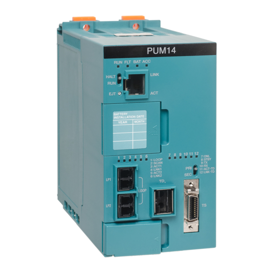
Chapter 8 Usage Constraints 8.1 Constraints on the controller and tool version CF622 is supported by type1 light controller PUM11, PUM12 and PUM14. CF622 as CF611 mode is supported by type1 light controller PUM11, PUM12, PUM14, model 2000 controller S2, S2T and S2E. -
Page 77: Constraints On The Installation
CF622 is mounted in the basic unit or the expansion unit. On-line attachment / detachment and on-line download are forbidden. CF622 cannot be mounted under the TC-net I/O Loop G2 I/O adapter, GA922. Unified Controller nv series type1 light Communication Interface Module (CF622) Instruction Manual... - Page 78 Chapter 8 Usage Constraints 6F8C1583...
- Page 79 Appendix A Specifications A.1 General specifications ············································· A.2 CF622 specifications ··············································· A.3 CF622 transmission specifications ···························...
- Page 80 Appendix A Specifications A.1 General specifications Table A-1 General specifications Item Specification Remarks Operating temperature range 0 to 55℃ Storage temperature range -40 to 70℃ Note1 10 to 95%RH, level RH2 Operating humidity range (no condensation) Dust Dust 0.3mg/m3 (no conductive dust) 2 (usually, no conductive contamination) or Degree of contamination less...
- Page 81 Controller nv series type1 light Note 2 Insertions/withdrawals 50 times durability (Note 2) If CF622 operates on CF611 mode, model 2000 (S2, S2T, S2E) controller can support CF622. Unified Controller nv series type1 light Communication Interface Module (CF622) Instruction Manual...
- Page 82 Appendix A Specifications A.3 CF622 transmission specifications Table A-3 CF622 transmission specifications Transmission Port Normal mode CF611 mode Item Transmission Interface RS-232C RS-485 RS-232C 6pin screw clamp 9pin D-sub connector 9pin D-sub connector Detachable terminal Connector Socket (female) Socket (female) block Metric screw thread Metric screw thread...
- Page 83 Appendix B Outside Dimensions B.1 CF622 module ························································ B.2 CF622 implemented in the base unit ·························...
- Page 84 Appendix B Outside Dimensions B.1 CF622 module The following figure shows the outside dimensions of CF622. 35mm 105mm 111.5mm Figure B-1 CF622 outside dimensions 6F8C1583...
- Page 85 B.2 CF622 implemented in the base unit B.2 CF622 implemented in the base unit 115mm 121.9mm Figure B-2 CF622 implemented in the base unit outside dimensions Unified Controller nv series type1 light Communication Interface Module (CF622) Instruction Manual...
- Page 86 Appendix B Outside Dimensions 6F8C1583...
- Page 87 Appendix C Related Products C.1 Accessories ··························································· C.2 Recommended communication cables ······················...
- Page 88 Appendix C Related Products C.1 Accessories Table C-1 Accessories Item Qty. Remarks RS-232C connector cover: CH1 attached to CF622 RS-485 terminal block attached to CF622 M4 type screw used at top of the module Remarks ・The size of the CH1 connector screw is M2.6. C.2 Recommended communication cables C.2.1 RS-232C cable...
- Page 89 Appendix D ASCII code chart...
- Page 90 Appendix D Decimal – Hexadecimal Conversion Table Table D-1 ASCII code chart High-order 4-bit DE SP “ 5 EQ NK & ‘ G W g w BS CN HT EM B HM EC C CL → < ¥ D CR ←...
- Page 91 Appendix E Sample programs Normal mode transmission parameters setting ···················· Data receiving program for type1 light / S2 ·························· Data sending program for type1 light / S2 ··························· Data receiving program for S2T / S2E ································· Data sending program for S2T / S2E ···································...
- Page 92 Appendix E Sample programs E.1 Normal mode transmission parameters setting This chapter describes a sample program of setting CH1 (RS-232C) parameters. This program can operate in following environment. Controller Module mode Remarks type1 light normal mode ■ Variable Local variable Name Type Description...
- Page 93 In order to clear Parameters setting request, move 0 to “Param.Command” and write “Param.Command” to address 8961 using MWRITE instruction. If “Status Information (address 8960)” equals 8000H, set “Done” to 1. Unified Controller nv series type1 light Communication Interface Module (CF622) Instruction Manual...
- Page 94 Appendix E Sample programs ■ Describe MOVE_WORD MOVE_UINT 16#000D Param.Delimiter 6000 Param.Timeout MOVE_WORD MOVE_UINT 16#0001 Param.Mode Param.Rcv MsgLen MOVE_WORD MOVE_WORD Param.Wire Param.RSCSCtrl MOVE_UINT MOVE_UINT Param.SndMsgLen 16#0054 Param.Format MOVE_UINT Param.AddMsgLen MOVE_WORD MWRITE Trash |↑| 16#8000 Param.Command Target 8961 TADDR Param.Command MREAD EQ_WORD Trash Enable...
- Page 95 |↑| Target 8972 TADDR Param.Delimiter MOVE_WORD MWRITE Enable Trash |↑| 16#0000 Param.Command Target 8961 TADDR Param.Command MREAD EQ_WORD Enable Trash Enable Done Param.Status Target 16#8000 8960 TADDR Param.Status Unified Controller nv series type1 light Communication Interface Module (CF622) Instruction Manual...
- Page 96 Appendix E Sample programs E.2 Data receiving program for type1 light / S2 This chapter describes a sample program of data receiving using CH1 (RS-232C). This program can operate in following environment. Controller Module mode Remarks type1 light normal mode CF611 mode Receive data size restricted to 160W.
- Page 97 IOStatus{BOOL}[11] IOCmd{BOOL}[11] RX_RDY RX_ST UFUN_MREAD IOStatus{BOOL}[11] IOCmd{BOOL}[11] Target 16#2800 TADDR Done RcvData RX_ERR RX_ST MREAD IOStatus{BOOL}[9] IOCmd{BOOL}[11] Target 16#2307 TADDR Error ErrData ADD_DINT RcvCntr RcvCntr Done || || Unified Controller nv series type1 light Communication Interface Module (CF622) Instruction Manual...
- Page 98 Appendix E Sample programs ■ UFUN_MREAD expansion < RETURN > MOVE_DINT MOVE_WORD SavedXI TADDR Address MOVE_DINT MOVE_DINT Offset REPEAT LT_UINT SEL_UINT Size SUB_UINT Size MREAD Trash Address TADDR P{WORD}[XI Size WORD_TO_U ADD_UINT UINT_TO_W Address Address Size 6F8C1583...
- Page 99 E.2 Data receiving program for type1 light / S2 ADD_DINT UINT_TO_D Size UNTIL LE_UINT Trash END_REPEAT MOVE_DINT Trash UFUN_MREAD SavedXI Unified Controller nv series type1 light Communication Interface Module (CF622) Instruction Manual...
- Page 100 Appendix E Sample programs E.3 Data sending program for type1 light / S2 This chapter describes a sample program of data sending using CH1 (RS-232C). This program can operate in following environment. Controller Module mode Remarks type1 light normal mode CF611 mode Send data size is restricted to 160W.
- Page 101 IOCmd{BOOL}[15] |↑| Target 16#2C00 TADDR SndData TX_CMP TX_ST IOStatus{BOOL}[14] IOCmd{BOOL}[15] Done TX_ERR TX_ST MREAD IOStatus{BOOL}[13] IOCmd{BOOL}[15] |↑| Target 16#2308 TADDR Error ErrData ADD_DINT SndCntr SndCntr Done || || Unified Controller nv series type1 light Communication Interface Module (CF622) Instruction Manual...
- Page 102 Appendix E Sample programs ■ UFUN_MWRITE expansion < RETURN > MOVE_DINT MOVE_WORD MOVE_DINT MOVE_DINT SavedXI TADDR Address Offset REPEAT LT_UINT SEL_UINT Size SUB_UINT Size MWRITE Trash Address TADDR P{WORD}[XI Size WORD_TO_U ADD_UINT UINT_TO_W Address Address Size ADD_DINT UINT_TO_D Size 6F8C1583...
- Page 103 E.3 Data sending program for type1 light / S2 UNTIL LE_UINT Trash END_REPEAT MOVE_DINT Trash UFUN_MWRITE SavedXI Unified Controller nv series type1 light Communication Interface Module (CF622) Instruction Manual...
- Page 104 Appendix E Sample programs E.4 CF611 mode data receiving program for S2T/S2E This chapter describes 256 byte (160W) data receive program for CF611 mode. In this case, CF622 as CF611 mode is mounted in slot No. 0 (next to the S2T/S2E module). Received data are stored in D0000 to D0127.
- Page 105 D1127 before this program runs. When an error is occurred, the module parameter is stored at D3000 to D3015. 1. Writing trans data 2. Start data sending 3. Sending is complete 4. Error is occurred 5. Sending is unsuccessful Unified Controller nv series type1 light Communication Interface Module (CF622) Instruction Manual...
- Page 106 Appendix E Sample programs 6F8C1583...
- Page 107 Unified Controller nv series type1 light Communication Interface Module (CF622) April 2016 1st Edition TOSHIBA CORPORATION Infrastructure Systems & Solutions Company Industrial Systems & Components Division 72-34, Horikawa-cho, Saiwai-ku, Kawasaki 212-8585, Japan © Toshiba Corporation 2016 No part of this document may be reproduced All Right Reserved.
- Page 108 1583.1.1605...