
Related Manuals for Toshiba Black Pear


Summary of Contents for Toshiba Black Pear
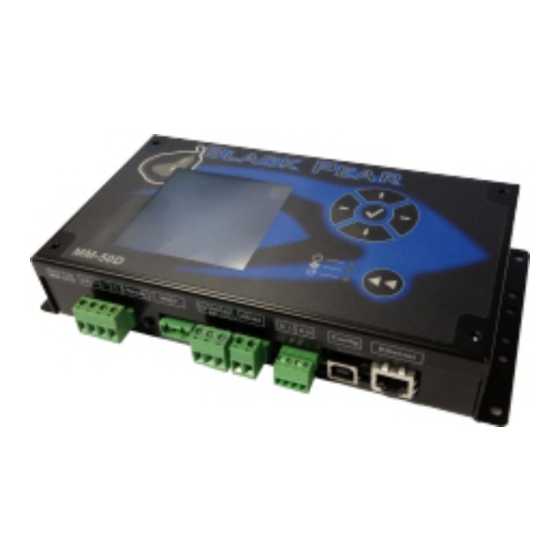
- Page 1 BMS Interface for Toshiba Air-Conditioning Installation and User Guide www.microtrol.co.uk...
- Page 2 BACnet is a registered trademark of ASHRAE (American Society of Heating, Refrigerating and Air-Conditioning Engineers, Inc.)
-
Page 3: Table Of Contents
Appendix A : Physical Dimensions ..................30 Appendix B : Reset Button and Factory Defaults ..............31 Appendix C : Trend Outstation Memory Usage (TT-64x only) ..........33 Appendix D : Toshiba Error Code Cross-Reference ............. 35 Appendix E : Document Revision History ................37... -
Page 4: Supplied Parts
1. Supplied Parts Black Pear with display Black Pear without display USB cable Cat-5 ‘Straight-Through’ Ethernet cable DIN-rail clips... -
Page 5: Important Information
Make all connections securely so that any outside forces acting on the cables are not applied to the terminals. Never modify or repair the Black Pear by yourself. Any attempt to do so will void the warranty. To dispose of this product, consult your dealer. -
Page 6: Product Overview
Trend via ethernet. (Also requires an IQ3/4 outstation with spare memory). The BACnet and Trend models also have Modbus available The Black Pear can also be used on systems where a central controller is already present. 3.1 Product Variants With Display... -
Page 7: Connection Details
Common Fig. 1 Connection Details 4.1 Power Supply The Black Pear requires a 24v AC supply and has a consumption not exceeding 5VA. The internal fuse is rated T630mA. THIS EQUIPMENT MUST BE EARTHED 4.2 HVAC Communications Network ( TCC-LINK ) Connect to outdoor unit terminals U3 and U4, as per a standard central controller. -
Page 8: Serial Communications Ports
4.3 Serial Communications Ports These connectors provide access to the Modbus registers using RS232 or 2-wire RS485. The port configuration is as follows: Modbus RTU 9600 baud, 8 data bits, no parity, 1 stop bit 9 PIN D-SUB FEMALE Serial Comms Port Pin 2 To PC... -
Page 9: Digital Input / Output
Ensure that the correct USB driver has been installed prior to connecting the Black Pear to a PC. 4.6 Ethernet The Black Pear is a 10/100Base-T half/full duplex device. It supports auto-negotiation and also features auto-crossover (Auto-MDIX), allowing the use of either a straight-through or crossover cable. -
Page 10: Air-Conditioning Address Configuration
5. Air-Conditioning Address Configuration Black Pear Outdoor (System Address 1) U1/U2 Indoor Unit Indoor Unit Indoor Unit U3/U4 (DN 03 = 1) (DN 03 = 2) (DN 03 = 3) Outdoor (System Address 2) U1/U2 Indoor Unit Indoor Unit Indoor Unit... - Page 11 The systems need to be set up as if a standard Toshiba central controller is to be fitted. The Black Pear can replace or work in parallel with a Toshiba central controller. Each refrigerant system must have a separate line address and the network address (Configuration Item 03) must be set between 1 and 64.
-
Page 12: User Interface ( Display Version )
6. User Interface ( Display Version ) Power LED Navigation Buttons HVAC Network LED Flashes on a valid incoming Enter/Accept Button message BMS Network LED Flashes on a valid incoming Back/Cancel Button message Main Menu System Overview Configuration Unit Modbus Network Status Unit... -
Page 13: Main Menu
The Black Pear has been restarted and is preparing to start scanning the HVAC network. Searching… The Black Pear is performing an initial scan to determine which unit addresses are active on the HVAC network. The progress bar shows how much of the scan has been performed. -
Page 14: System Overview
6.2 System Overview Displays an 8 by 8 grid showing the address of any unit discovered by the Black Pear, in the address range 1 to 64. Pressing the key will return to the Main Menu screen. Selection Cursor. Controlled using the navigation buttons. -
Page 15: Unit Status Screen
6.3 Unit Status Screen Group Master Slave Unit Status Status Screen Screen This screen shows the status of a single fan coil. Pressing the key cycles backward and forward through all available fan coils. key will return to the System Overview screen. Only a ‘Group Master’... -
Page 16: Modbus Interface
Cat-5 cable (Supplied) Serial Comms Outdoor cable (Not supplied) Units Indoor Units TCC-LINK Black Pear TM-64x Fig. 6 Modbus System Example 7.1 Port Configurations RS232/RS485 interface Modbus RTU 9600 baud, 8 data bits, no parity, 1 stop bit Network interface Modbus/TCP... -
Page 17: Hvac Status And Control Registers
1 to 24. The Base Slave Address can be adjusted from 1 up to 200. A setting of 200 means the Black Pear will respond to msgs for slaves 200 to 223. This is useful to prevent address clashing when the Black Pear unit is attached to a serial communications network containing multiple Modbus devices. -
Page 18: Additional Register Usage
On/Off and Inhibit can also be accessed via ‘Coils’. Each slave contains 12 coils, organised as follows: Coil Offset Definition Unit A On/Off (R) Unit A On/Off (W) Unit B On/Off (R) Unit B On/Off (W) Unit C On/Off (R) Unit C On/Off (W) Unit A Inhibit (R) Unit A Inhibit (W) -
Page 19: Parameter Settings
7.4 Parameter Settings Parameter Settings Notes Return Air Temperature C to 92 Read-only ‘Hi-res’ Return Air -35.0 C to 92.0 register contains the value multiplied by 10. eg. 235 = 23.5 Error Code 4 digit error code where Read-only 8000 = ‘No Error’ See Appendix D 6999 = ‘Unit Not Present’... -
Page 20: Modbus Table Overview
7.5 Modbus Table Overview Single Slave Access Coil Base Offsets General Extended Extra Info Unit General Extended Slave Info Base Info Base Base Address On/Off Inhibit Info Base Info Base Offset Offset Offset Offset Offset 1020 1000 1030 1010 1040 1080 1110 1090... - Page 21 Single Slave Access Coil Base Offsets General Extended Extra Info Unit General Extended Slave Info Base Info Base Base Address Info Base Info Base On/Off Inhibit Offset Offset Offset Offset Offset 1540 1570 1550 1580 1620 1650 1630 1660 1640 1670 1710 1740...
-
Page 22: Trend Interface (Tt-64X Only)
TT-64x Fig. 7 Trend System Example The Black Pear connects via Ethernet to a CNC or the virtual CNC port of a Trend IQ outstation, and uses sensors, switches and knobs defined in the IQx memory to mirror a range of HVAC parameters, making them available on a Trend network. -
Page 23: Trend Process Description
Some Trend systems will generate ‘network alarms’ due to the repeated connection and disconnection of the Black Pear to the CNC. Setting the CNC Usage = 0 will allow a single Black Pear to remain connected to the CNC, thus preventing these alarms from being generated. -
Page 24: Trend Iqx Outstation Configuration
298 to 301 302 to 305 The Black Pear can be configured to enable only those objects of interest to the user, therefore reducing the memory overhead required in the IQ outstation. Any objects enabled in the Black Pear which aren’t defined in the Trend outstation will simply be ignored during the polling sequence. -
Page 25: Parameter Settings
8.3 Parameter Settings See the table in Section 7.4 for a list of valid parameter settings. Notes: As of firmware v2.29, the return air sensor and the setpoint knob will contain temperatures valid to 1 dp (with 0.5 C resolution). Setting the setpoint to 1 dp is reliant on the HVAC unit accepting setpoint commands to this resolution. -
Page 26: Bacnet Interface (Tb-64X Only)
Units Indoor Units TCC-LINK Black Pear TB-64x Fig. 8 BACnet System Example The BLACK Pear TB-64x is designed to work with a BACnet/IP network as described in the ANSI/ASHRAE Standard 135-2004. Property Setting Segmentation Not Supported Maximum APDU length supported... -
Page 27: Object Types
9.1 Object Types Object Type Supported Analog Input Analog Output Analog Value Binary Input Binary Output Binary Value Calendar Command Device Event Enrollment File Group Loop Multi-State Input Multi-State Output Notification Class Program Schedule Averaging Multi-State Value Trend Log 9.2 Service List Supported Services Read Property Read Property Multiple... -
Page 28: Object List
9.3 Object List Object Object Type Instance ‘Present Value’ Notes Settings On/Off (Setup) Binary Output 1xxx01 Inactive:Off Active:On On/Off (State) Binary Input 1xxx02 Inactive:Off Active:On Error Code Analog Input 1xxx03 4 digit error code where Appendix D 8000= ‘No Error’ 6999= ‘Unit Not Present’... - Page 29 Object Object Type Instance ‘Present Value’ Notes Settings Air Direction (Setup) Multi-State Output 1xxx13 01: Horizontal 02: 22½ deg 03: 45 deg 04: 67½ deg 05: Vertical 06: Swing 07: Hold Air Direction (State) Multi-State Input 1xxx14 01: Horizontal 02: 22½ deg 03: 45 deg 04: 67½...
-
Page 30: Object Names
9.4 Object Names Object Object Name Notes On/Off (Setup) nnn (ON_w) On/Off (State) nnn (ON_r) Error Code nnn (ECode) Operation Mode (Setup) nnn (MD_w) Operation Mode (State) nnn (MD_r) Fan Speed (Setup) nnn (FS_w) Fan Speed (State) nnn (FS_r) Room Temperature nnn (RA) Setpoint Temperature (Setup) nnn (SP_w) -
Page 31: System Objects
9.5 System Objects There are 2 ‘System’ objects contained within the Black Pear, which are classed as global objects. A description of each is detailed below. System Object Description HVAC Network Status Read-only object providing an indication of the communication status between the Black Pear and the HVAC network. -
Page 32: Appendix A : Physical Dimensions
Appendix A : Physical Dimensions 210mm 91mm 117mm 202mm 39mm Power Reset HVAC Serial Comm Digital 10/100 Supply Button Ports In/Out Base-T Ethernet Fig. 9 Dimensions The holes marked ‘A’ should be used when mounting the enclosure on a back panel. The holes marked ‘B’... -
Page 33: Appendix B : Reset Button And Factory Defaults
Appendix B : Reset Button and Factory Defaults The Reset Button has 2 functions : 1) To restore various internal settings to their factory default, 2) To force the unit into ‘bootloader’ mode ready for a firmware update. Function 1 – Restore Factory Defaults There are 2 levels to this function. - Page 34 Additional Setting Restored for Trend Interfaces (TT-64x): Pin Code Disabled Sensor Base Address Switch Base Address Knob Base Address Object Enable Mask All Objects Enabled OutStation Address CNC IP Address 192.168.1.1 CNC Address CNC Port Number 10001 CNC Usage Additional Settings Restored for BACnet Interfaces (TB-64x): Device ID UDP Port 47808...
-
Page 35: Appendix C : Trend Outstation Memory Usage (Tt-64X Only)
Appendix C : Trend Outstation Memory Usage (TT-64x only) 1) The table below shows how much memory (in brIQs) each parameter requires : Parameter Trend Module Size (brIQs) Comments Return Air Temp Sensor Error Code Sensor On/Off Switch Inhibit Switch Setpoint Knob Mode... - Page 36 1) When calculating the number of outstations required for a system, it is recommended to allow some spare capacity for strategy and other configuration data. 2) A single Black Pear device can only communicate with 1 Trend outstation, but multiple Black Pears can communicate with the same Trend outstation, provided there is enough...
-
Page 37: Appendix D : Toshiba Error Code Cross-Reference
Appendix D : Toshiba Error Code Cross-Reference Black Pear Toshiba Description Error Code Error Code 1005 Sending error in TCC-LINK central control device 1006 Receiving error in TCC-LINK central control device 1012 Batch alarm of general-purpose equipment control interface 2001... - Page 38 Follower indoor unit error (Group error) 7031 Follower indoor unit error (Group error) Note: For further information regarding the above error codes, please contact your local Toshiba A/C supplier, or Toshiba A/C technical support. Special Black Pear Description Error Codes 6999...
-
Page 39: Appendix E : Document Revision History
Appendix E : Document Revision History Date Document Ver Firmware Ver Comments 06/08/2013 v1.00 v2.03 Started Toshiba specific manual. 12/08/2013 v1.01 v2.04 First draft version. 02/10/2013 v1.02 v2.07 First complete version Added example addressing diagram. Added error code cross-reference. 01/05/2014 v1.03... - Page 40 Microtrol Ltd 16 Elgar Business Centre Moseley Road Hallow Worcester WR2 6NJ Tel: +44 (0)1905 641910 Email: sales@microtrol.co.uk...