
Related Manuals for Toshiba Carrier RBM-Y0611F4PUL


Summary of Contents for Toshiba Carrier RBM-Y0611F4PUL
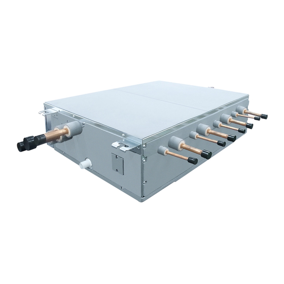
- Page 1 1 11 843 110 1 Installation Manual Multi Port Flow Selector Unit RBM-Y0611F4PUL RBM-Y0611F6PUL Installation Manual English Manuel d’installation Français...
-
Page 2: Table Of Contents
Multi Port Flow Selector Unit (hereafter "Flow Selector unit") Thank you very much for purchasing TOSHIBA / Carrier Super Heat Recovery Multi (SHRM) Air conditioner. Please read this manual carefully before using your Flow Selector unit. • When installing an indoor or outdoor unit, follow the installation manual supplied with the unit. -
Page 3: Accessory Parts And Parts To Be Procured Locally
Accessory parts and Parts to be procured locally Q'ty RBM-Y0611 Part name Shape Usage F4PUL F6PUL Accessory parts Binding band (L11.8" (L300)) For fi xing heat insulation of fl exible hose Binding band (L11.8" (L300)) For fi xing heat insulating pipes Q'ty RBM-Y0611 Part name Shape... -
Page 4: Precautions For Safety
PRECAUTIONS FOR SAFETY Installing, starting up, and servicing air conditioning equipment can be hazardous due to system pressures, • After the installation work, confi rm that refrigerant gas does not leak. electrical components, and equipment location (roofs, elevated structures, etc.). If refrigerant gas leaks into the room and fl... -
Page 5: Installation Of New Refrigerant Air Conditioner
INSTALLATION OF NEW REFRIGERANT SELECTION OF INSTALLATION PLACE AIR CONDITIONER CAUTION This air conditioner adopts the new HFC refrigerant (R410A) which does not deplete the ozone layer. Do not install the air conditioner at place where combustible gas may leak. •... -
Page 6: Installation Of Flow Selector Unit
INSTALLATION OF FLOW SELECTOR Installation under high-humidity atmosphere In some cases including the rainy season, especially inside of the ceiling may become high-humidity atmosphere UNIT (dew-point temperature: 73 °F (22.8 °C) or higher). 1. Installation to inside of the ceiling with tiles on the roof 2. - Page 7 Installation of hanging bolt External view Use W3/8" (M10) hanging bolts (4 pcs, locally procured). (Unit: in (mm)) Matching to the existing structure, set pitch according to size in the unit external view as shown below. Control Box New concrete slab Install the bolts with insert brackets or anchor bolts.
-
Page 8: Drain Piping
DRAIN PIPING Connection of drain hose • Insert the attached drain hose into the drain pipe connecting port on the drain pan up to the end. • Fit the attached hose band to the end of the pipe connecting port, and then tighten it securely. CAUTION REQUIREMENT Following the Installation Manual, perform the drain piping work so that water is properly drained. -
Page 9: Refrigerant Piping
REFRIGERANT PIPING Heat insulating process • Using the attached drain hose heat insulator, lap the connecting section and the drain hose without clearance, and then tighten with two handing band so that heat insulator does not open. WARNING • Covering the attached drain hose heat insulator, lap the heat insulator (locally procured) to the drain pipe without clearance. - Page 10 Piping dimensions Pipe connecting process They vary depending on the outdoor unit. For details, refer to the Installation Manual attached to the outdoor unit. • Connect the pipes. • Use stopper-pipe (accessory) to the port to which indoor unit is not connected. Outdoor unit FS unit •...
-
Page 11: Electrical Connection
ELECTRICAL CONNECTION Airtight test/Air purge, etc. For airtight test, air purge, addition of refrigerant, and gas leak check, follow the Installation Manual attached to the outdoor unit. CAUTION REQUIREMENT • Consult local building codes, NEC (National Electrical Code) or CEC (Canadian Electrical Code) for special requirements. - Page 12 Wire connection U1 U2 U1 U2 U1 U2 Indoor unit REQUIREMENT • Connect the wires matching the terminal numbers. Incorrect connection causes a trouble. • Pass the wires through the bushing of wire connection holes of the Flow Selector unit. •...
- Page 13 Unit: in (mm) 0.4" L1 L2 (10) 0.2" 0.4" (10) See the fi gure on the left for connecting wires 2.0" to the terminal. 7.1" 1.6" (50) (40) (180) Ground wire Communication wire Power supply wire Communication wires Communication wiring Terminal block for remote control wiring of indoor unit...
- Page 14 System wiring diagram Outdoor Power supply Outdoor Power supply Circuit breaker Circuit breaker Header outdoor unit Follower outdoor unit Ground Ground L1 L2 L3 U1 U2 S U3 U4 U5 U6 S U1 U2 U3 U4 U5 U6 L1 L2 L3 U1 U2 S U3 U4 U5 U6 S terminal terminal...
- Page 15 Setting when connecting How to set up CODE No. [ 0E ] Caution to connection of indoor unit q Case that FE/FD setting is not necessary indoor units to FS (Flow It is necessary to set up in case of the group control. When connecting the indoor units to FS unit, it is FS unit necessary to set up the CODE No..
- Page 16 In case of connecting Drain pump (locally procured) <In case of connecting two group operations of <Incorrect connection examples> indoor units> Incorrect It's available to connect the operation-off signal input cable of fl oat switch. FS unit FS unit Single port type FS unit At that time, the cable is taken from the hole on the control-box bottom side and connect to CN34 on PC board of unit No.1 (showing “1”...
- Page 17 Unité de sélection du débit multi Port (ci-après « unité de sélection du fl ux ») Nous vous remercions d’avoir choisi un climatiseur Super Multi Réversible (S-HRM) TOSHIBA / Carrier. Veuillez lire attentivement ce Manuel avant d’utiliser Unité de sélrction de débit.
-
Page 18: Pièces Annexes Et Pièces À Se Procurer Localement
Pièces annexes et Pièces à se procurer localement Quantité RBM-Y0611 Nom de la pièce Forme Emploi F4PUL F6PUL Pièces annexes Pour la fi xation de l'isolation thermique du Bande de liaison (L11,8" (L300)) tuyau fl exible Quantité Pour la fi xation des tubes d'isolation RBM-Y0611 Nom de la pièce Forme... -
Page 19: Précautions Pour La Sécurité
PRÉCAUTIONS POUR LA SÉCURITÉ L'installation, la mise en route et l'entretien de l'équipement de climatisation peuvent être dangereux à cause des • Une fois l’installation terminée, vérifi ez que le gaz réfrigérant ne fuit pas. pressions présentes dans le système, des composants électriques et de l'emplacement de l'équipement (toits, Si du gaz réfrigérant fuit dans la pièce et s’écoule près d’une source de chaleur, telle qu’une cuisinière, un gaz structures élevées, etc.). -
Page 20: Installation De La Climatisationà Nouveau Réfrigérant
INSTALLATION DE LA CLIMATISATION CHOIX DE L’EMPLACEMENT À NOUVEAU RÉFRIGÉRANT D’INSTALLATION Cette climatisation utilise le nouveau réfrigérant HFC (R410A), non nuisible pour la couche d’ozone. ATTENTION • Le réfrigérant R410A est susceptible d’être perturbé par des impuretés comme de l’eau, des membranes oxydantes ou de l’huile, ceci en raison d’une pression plus élevée que celle des réfrigérants précédents, N’installez pas la climatisation dans un emplacement susceptible d’être exposé... -
Page 21: Installation De L'unité De Sélection De Débit
INSTALLATION DE L’UNITÉ DE Installation dans une ambiance très humide Dans certaines conditions, y compris la saison des pluies, l’atmosphère devient très humide, surtout dans le SÉLECTION DE DÉBIT plafond (température du point de rosée: 73 °F (22,8 °C) ou davantage). 1. - Page 22 Installation du boulon de suspension Vue externe Utilisez des boulons de suspension W3/8" (M10) (4 pièces, vendues séparément). (Unité : pouces (mm)) En tenant compte de la structure existante, déterminez le pas de vis des tiges fi letées et vérifi ez la distance séparant ces tiges grâce aux dimensions données cidessus dans le schéma coté...
-
Page 23: Tuyauterie De Vidange
TUYAUTERIE DE VIDANGE Raccordement du tuyau de vidange • Insérez le tuyau de vidange fi xé dans le tuyau de vidange reliant le port sur le bac jusqu'au bout. • Montez le collier de serrage fi xé à l'extrémité du port de raccordement du tuyau, puis serrez fermement. ATTENTION EXIGENCE Consultez le manuel d'installation et effectuez les opérations se rapportant aux tuyaux de vidange, afi... -
Page 24: Tuyauterie De Réfrigérant
TUYAUTERIE DE RÉFRIGÉRANT Procédé de calorifugeage • En utilisant l'isolant de chaleur du tuyau de vidange fi xé, enroulez la section de raccordement et le tuyau de vidange sans jeu, puis serrez avec deux bandes de telle sorte que l'isolant thermique ne s'ouvre pas. AVERTISSEMENT •... - Page 25 Dimensions de la tuyauterie Processus de raccordement de tuyaux Elles varient en fonction de l'unité extérieure. Pour plus de détails, reportez-vous au Manuel d’installation fi xé à • Branchez les tuyaux. l’unité extérieure. • Utilisez un tuyau d'arrêt (annexe) sur le port auquel l'unité intérieure n'est pas connecté. Unité...
-
Page 26: Raccordement Électrique
RACCORDEMENT ÉLECTRIQUE Test d’étanchéité/Purge de l’air, etc. Pour les tests d’étanchéité, la purge d’air, l’ajout de réfrigérant et la vérifi cation des fuites de gaz, suivez les consignes du Manuel d’installation fi xé à l’unité extérieure. ATTENTION EXIGENCE • Consultez les codes de construction locaux, le NEC (National Electrical Code) ou le CEC (Canadian Electrical Code) pour les exigences spéciales. - Page 27 Connexion de câble U1 U2 U1 U2 U1 U2 Unité intérieure EXIGENCE • Connectez les câbles correspondant aux numéros de terminaux. Une connexion incorrecte provoque un problème. • Faites passer les câbles à travers la douille de trous de connexion de l'unité de sélection de débit. •...
- Page 28 Unité : pouces (mm) 0,4" L1 L2 (10) 0,2" 0,4" (10) Voir la fi gure de gauche pour connecter les fi ls à 2,0" la borne 7,1" 1,6" (50) (40) (180) Vis de terre Câble de communication Câblage d'alimentation Câbles de communication Câblage de communication Bornier de raccordement de la télécommande de...
- Page 29 Schéma des câbles du système Alimentation extérieure Alimentation extérieure Interrupteur du Interrupteur du disjoncteur disjoncteur Unité principale Unité secondaire Borne Borne L1 L2 L3 U1 U2 S U3 U4 U5 U6 S U1 U2 U3 U4 U5 U6 L1 L2 L3 U1 U2 S U3 U4 U5 U6 S de terre de terre...
- Page 30 Réglage lors du raccordement Configuration d’un CODE No. [ 0E ] q Cas où la configuration FE / FD n'est pas Précautions à prendre pour raccorder nécessaire une unité intérieure des unités intérieures au SD La configuration est nécessaire en cas de commande de groupe.
- Page 31 <En cas de raccordement de deux opérations de <Exemple de mauvais raccordement> En cas de raccordement de pompe de vidange (vendu sur place) groupe d’unités intérieures> Incorrect Vous pouvez connecter le câble d'entrée de signal de fi n d'opération de l'interrupteur à fl otteur. Unité...
- Page 32 TOSHIBA CARRIER (THAILAND) CO.,LTD. 144/9 MOO 5, BANGKADI INDUSTRIAL PARK, TIVANON ROAD, TAMBOL BANGKADI, AMPHUR MUANG, PATHUMTHANI 12000, THAILAND. 1118431101...