
Related Manuals for GE E4H Series


Summary of Contents for GE E4H Series
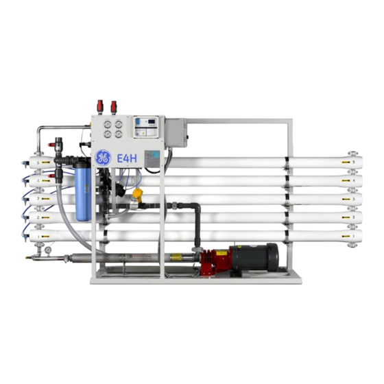
- Page 1 E4H Series Water Purification Machines Operation and Maintenance Manual 16,000 GPD to 43,200 GPD 60.6 m /day to 163.5 m /day December 21, 2006 Document PN 1163955, Rev C http://www.gewater.com...
-
Page 2: Table Of Contents
DLX Electrical System ....................14 PREPARATION AND START-UP ......................14 3.1. Pretreatment for Water Purification................14 3.2. Start-Up ............................15 OPERATION AND MAINTENANCE....................18 4.1. Daily Log Sheets ........................19 4.2. Pre-Filter............................19 4.3. Flushing ............................19 4.4. Cleaning............................20 4.4.1. CLEANING PROCEDURE ....................20 E4H Series Operation & Maintenance Manual... - Page 3 Machine Warranty/Guarantee...................31 9.2. Desal* Membrane Element Workmanship Warranty ..........32 9.3. START-UP DATA.........................35 9.4. DAILY LOG FOR GE WATER & PROCESS TECHNOLOGIES ..........MEMBRANE MACHINES......................37 List of Tables Table 1. Flow Specifications for E4H Machines, 50-75% Recovery........10 Table 2. Feed Water Requirements ....................11 Table 3.
- Page 4 Technician, Security, and Operator Level Menus............44 Technician Level Menus ......................45 A.1.8 Operation...........................46 A.1.9 Relays ..........................49 A.1.10 Alarms ..........................50 A.1.11 Flow Meters........................51 A.1.12 4-20 mA Output ......................52 A.1.13 System Setup ........................53 A.1.14 Clock.............................57 Security Level Menus......................58 Operator/View Level Menus ....................59 E4H Series Operation & Maintenance Manual...
-
Page 5: Description
Feed water solution is separated in to two streams, permeate and concentrate, and collected from both sides of the membrane. A semipermeable RO membrane, under sufficient pressure, allows passage of purified water while rejecting and concentrating dissolved and suspended solids. E4H Series Operation & Maintenance Manual... -
Page 6: Membrane Elements
The spacer allows for movement of the concentrate past the membrane, and the permeate carrier carries the purified water out of the membrane element. GE Water & Process Technologies manufactures a patented spiral wound membrane element with a turbulent flow design. This membrane module collects the purified water within the central tube, the permeate tube. -
Page 7: Cip
33% is produced as purified water (permeate). 1.1.11. Salt (Ionic) Rejection The percent of dissolved salt rejected by the membrane, calculated from an average concentration over the membrane. E4H Series Operation & Maintenance Manual... -
Page 8: Flow Description
The pump feeds water to the membrane housings arranged in parallel and serial combinations. The direction of water flow is indicated by an arrow on each housing. Water is separated by the membrane within the membranes and leaves the housings in two streams: permeate and concentrate. E4H Series Operation & Maintenance Manual... -
Page 9: Machine Nomenclature
• Multi-stage centrifugal pump, SS construction (stainless steel castings with Noryl* stages) • Base model electrical package includes NEMA-1 enclosure with a 110 VAC, 60 Hz or 220 VAC, 50 Hz single-phase control circuit; applies to all ECN models E4H Series Operation & Maintenance Manual... -
Page 10: Dlx Model Option
18.8 (4.3) 26.2 (5.9) 30 (6.8) Concentrate 11.2-3.7 15-5 (3.4- 18.8-6.3 26.2-8.7 30-10 (6.8- Rate (2.5-0.8) 1.1) (4.3-1.4) (5.9-2.0) 2.3) Feed Rate 22.4-14.9 30-20 (6.8- 37.6-25.1 52.4-34.9 60-40 (13.6- (5.1-3.4) 4.5) (8.5-5.7) (11.9-7.9) 9.1) E4H Series Operation & Maintenance Manual... -
Page 11: Feed Water Specifications
Stated in Table 1 and factory set as stated on serial number label. 1.5.4. Operating Final Pressure Minimum - 200 psig (13.8 bar) Maximum - 235 psig (16.2 bar) 1.5.5. Pump Multi-stage centrifugal; approximate primary operating pressure of 190 psig (13.1 bar) excluding line pressure. E4H Series Operation & Maintenance Manual... -
Page 12: Membrane Rejection
2. INSTALLATION 2.1. Mounting E4H Series machines are equipped with a stand-alone frame, which supports the machine. At least 45 inches (114 cm) of space should be allowed on each end of the membrane element housings for removal and loading of membrane elements. If 45 inches (114 cm) are not available, the entire membrane element housing may need to be removed for membrane element replacement. -
Page 13: Valves Required For Cip, Ecn Models Only
2.2.2. Valves Required for CIP, ECN Models Only IMPORTANT NOTE: GE has installed a plugged pipe tee in the inlet line of the E4H units. This plug, when removed, will facilitate cleaning of the unit. A tee with (two) two-way valves or a single three-way valve should also be installed on the permeate and concentrate outlets to allow flow back to the cleaning tank. -
Page 14: Dlx Electrical System
A water analysis prior to start- up of the machine is required. To minimize the chances of calcium carbonate, calcium sulfate, or other salt precipitation on the membrane, GE Water & Process Technologies evaluates each application and water condition and makes specific recommendations to ensure continuity of the membrane membrane warranty. -
Page 15: Start-Up
The flow control center features a concentrate flow control valve, a recycle flow control valve, and a pressure gauge sensor point piped into the panel-mounted pressure gauge. NOTE: The autoflush valve is positioned in this flow control center. E4H Series Operation & Maintenance Manual... - Page 16 CAUTION: Operation of the pump backwards for even a short time can cause damage to the pump. Turn the ON/OFF switch to the ON position. The high-pressure pump will operate and the machine will begin to build pressure. As you are operating, be E4H Series Operation & Maintenance Manual...
- Page 17 See Table 1 for specified flow rates for various machine recoveries. When you have selected your desired flow rate, gradually adjust the concentrate flow control valve to achieve desired flow and use the recycle valve to bring the operating pressure up to 250 psi (17.3 bar). E4H Series Operation & Maintenance Manual...
-
Page 18: Operation And Maintenance
(flushing or cleaning as needed) must be kept. This log sheet will be required by GE Water & Process Technologies if a warranty question arises. 4. OPERATION AND MAINTENANCE The operation and maintenance of your GE Water &... -
Page 19: Daily Log Sheets
(pre-filter changes, flushing, cleaning, etc.) must be kept. Copies of the log can be made from the template. A copy of this log sheet will be required by GE Water & Process Technologies if a warranty question arises. -
Page 20: Cleaning
Cleaning may be required as often as once every week or as infrequently as every three months, depending upon the local water supply conditions. GE Water & Process Technologies recommends cleaning at least once a quarter to assure good membrane element performance and long membrane element life. -
Page 21: Draining Machine For Storage/Shipment
The RO is now ready for operation. 4.5. Draining Machine for Storage/Shipment Prior to shipping or outside storage of a GE Water & Process Technologies E4H Machine, the system should be cleaned with the appropriate cleaner, flushed with water, and protected from biological attack with the appropriate solution for TFC membrane. - Page 22 Install the clamp halves, and tighten the bolts until the clamp halves meet. 13. Re-connect any fittings that were removed when disassembling the membrane housings. E4H Series Operation & Maintenance Manual...
-
Page 23: Membrane Replacement
5.3. Storage Tanks Fiberglass, polyethylene and stainless steel storage tanks are available. All tanks are available with fittings installed at the factory. These tanks must be installed with even support along the bottom. E4H Series Operation & Maintenance Manual... -
Page 24: Troubleshooting
The operator can easily correct many of these problems; however, for those that persist or are not understood, you should contact the GE Water & Process Technologies technical support team. Have the following information available when calling the GE Water & Process Technologies technical support team: •... - Page 25 Replace or calibrate the gauge as gauge required. Service and CIP valves Verify water path to both is open. closed at the same time Restricted or reduced See the possible causes for low permeate flow rate permeate flow rate. E4H Series Operation & Maintenance Manual...
- Page 26 Change in incoming Open the concentrate valve and water quality flush. Test the water for pH, hardness, TDS, and iron content. A water analysis should be sent to GE Water & Process Technologies for review. Calibrate the monitor with a Inaccurate...
- Page 27 Check the fuses or circuit breakers; measure the voltage. Motor and/or pump See the pump instructions. Contact not operating properly. GE for repair of replacement. Alarm condition has Check for minimum inlet pressure turned off machine. and push alarm reset switch.
- Page 28 Chemical pump feed Relay setpoint not Determine whether you need the reverse of what you properly configured. relay configured for direct or reverse expected. setpoint feed. E4H Series Operation & Maintenance Manual...
- Page 29 See “ALARMS” in main menu. “Feed: High Alarm” exceeded the user- programmed high alarm value. {ALARM FLASHING} The feed flow has See “ALARMS” in main menu. “Feed: Low Alarm” exceeded the user- programmed low alarm value. E4H Series Operation & Maintenance Manual...
- Page 30 Check sensor wiring. “pH: Low Ref Voltage” exists in the pH sensor, {ALARM FLASHING} The CIP switch input None, unless the input is wired “CIP Switch Closed” condition has become incorrectly. asserted. Relays are locked out. E4H Series Operation & Maintenance Manual...
-
Page 31: Spare Parts List
7. SPARE PARTS LIST For detailed spare part lists, please refer to the manual addendum. Contact the GE Water & Process Technologies Customer Support Center to order parts. 8. RETURN GOODS AUTHORIZATION (RGA) PROCEDURE If you wish to return goods for repair, warranty evaluation and/or credit, please have your original sales order or invoice available when you call GE Water &... -
Page 32: Desal* Membrane Element Workmanship Warranty
9.2. Desal* Membrane Element Workmanship Warranty GE Osmonics, Inc. guarantees the proposed product to be free from defects in material or workmanship when operated in accordance with written instructions for a period of one year from start-up or fifteen months from receipt, whichever is shorter. - Page 33 GE Osmonics will replace the membrane element with a new membrane element and will charge the User for the portion of the 12 months that the membrane element was used plus incoming freight and local labor.
- Page 34 It is the obligation of the User to maintain frequent operating data records. GE Osmonics may request these records in the warranty evaluation. User must notify GE Osmonics at the very first sign of changes in operation of the Osmo machine or membrane elements.
-
Page 35: Start-Up Data
Post-Filter Pressure Primary Pressure Final Pressure µS/cm Feed Conductivity Concentrate µS/cm Conductivity Average Conductivity µS/cm Permeate Conductivity µS/cm (manual) Permeate Conductivity µS/cm (meter) % Passage Perm TDS/Avg TDS) Chlorine in Concentrate Low Pressure Switch Setting E4H Series Operation & Maintenance Manual... -
Page 37: Membrane Machines
9.4. DAILY LOG FOR GE WATER & PROCESS TECHNOLOGIES MEMBRANE MACHINES NOMENCLATURE: MACHINE MODEL NO: NAME OF COMPANY: SERIAL NO: PERIOD OF THIS SHEET: PRESS = PRESSURE CONC = CONCENTRATE, Q NOTE: Please record all calibrations of instruments or other occurrences related to this system. -
Page 38: Appendix A - Operation Of Lakewood Instruments 2450 Ro Controller
An operator password can help insure that the system will be operated only by authorized personnel. is a registered trademark of Echelon Corporation. ORKS E4H Series Operation & Maintenance Manual... - Page 39 1. 2450 Front Panel with Display E4H Series Operation & Maintenance Manual...
-
Page 40: Table 6. 2450 Input Specifications
CIP Switch Dry contact Water Meter Inputs Two, open collector type Table 7. 2450 Output Specifications Relays 3 Amps, 120 VAC each 4-20 mA Two, isolated with –35L RS232 Requires Windows-based PC with –RTC-RS2L E4H Series Operation & Maintenance Manual... -
Page 41: Table 8. 2450 Monitor Specifications
If you change the sensor used and do not verify the preamp setup for your attached sensor, the conductivity readings may be erroneous. Set up the preamp by using the following steps. E4H Series Operation & Maintenance Manual... -
Page 42: Table 9. Amplifier Settings In The Model 2450
0.03 543L 4 Elec 0-1000 0.03 543M 4 Elec 0-1000 0.38 543M 4 Elec 0-2500 0.38 A.1.5 Testing Continue to test the monitor’s accessories by following these instructions. 1. Return to the MAIN MENU. E4H Series Operation & Maintenance Manual... -
Page 43: Calibration Methodology
1. From the MAIN MENU, press 2 or highlight RELAYS and press ENT. 2. Press the number of the relay governing the operation you wish to control. 3. Press 2 or highlight SETPOINT CONTROL and press ENT. E4H Series Operation & Maintenance Manual... -
Page 44: Technician, Security, And Operator Level Menus
TECHNICIAN Level menu. The following pages illustrate the menu screens available in each security level. NOTE : If you personalize passwords, make sure they are recorded in a safe and secure place. E4H Series Operation & Maintenance Manual... -
Page 45: Technician Level Menus
A.6 Technician Level Menus E4H Series Operation & Maintenance Manual... -
Page 46: Operation
A.1.8 Operation E4H Series Operation & Maintenance Manual... - Page 47 E4H Series Operation & Maintenance Manual...
- Page 48 E4H Series Operation & Maintenance Manual...
-
Page 49: Relays
A.1.9 Relays E4H Series Operation & Maintenance Manual... -
Page 50: Alarms
A.1.10 Alarms E4H Series Operation & Maintenance Manual... -
Page 51: Flow Meters
A.1.11 Flow Meters E4H Series Operation & Maintenance Manual... -
Page 52: Ma Output
A.1.12 4-20 mA Output E4H Series Operation & Maintenance Manual... -
Page 53: System Setup
A.1.13 System Setup E4H Series Operation & Maintenance Manual... - Page 54 E4H Series Operation & Maintenance Manual...
- Page 55 E4H Series Operation & Maintenance Manual...
- Page 56 E4H Series Operation & Maintenance Manual...
-
Page 57: Clock
A.1.14 Clock E4H Series Operation & Maintenance Manual... -
Page 58: Security Level Menus
A.7 Security Level Menus E4H Series Operation & Maintenance Manual... -
Page 59: Operator/View Level Menus
A.8 Operator/View Level Menus E4H Series Operation & Maintenance Manual... - Page 60 Asia/Pacific visiting gewater.com or Trevose, PA Watertown, MA Heverlee, Belgium Shanghai, China e-mailing custhelp@ge.com. +1-215-355-3300 +1-617-926-2500 +32-16-40-20-00 +86 (0) 411-8366-6489 ©2006, General Electric Company. All rights reserved. *Trademark of General Electric Company; may be registered in one or more countries.