Toshiba Q7 Installation And Operation Manual
Adjustable speed drive
Hide thumbs
Also See for Q7:
- Installation and operation manual (46 pages) ,
- Installation and operation manual (175 pages)

Related Manuals for Toshiba Q7


Summary of Contents for Toshiba Q7
- Page 1 Reliability in motion Q7 Adjustable Speed Drive Installation and Operation Manual Document Number: 54963-000 Date: November 2003...
- Page 2 Contacting Toshiba’s Customer Support Center Toshiba’s helpful Customer Support Center has been rated among the best in the industry and can be contacted to obtain assistance in resolving any Q7 Adjustable Speed Drive system problem that you may experience or to provide application information.
- Page 3 The Q7 ASD is also compatible with Windows CE and PALM The Q7 ASD is a very powerful tool, yet surprisingly simple to operate. The Q7 ASD has an easy-to-read LCD screen that provides easy access to the many monitoring and programming features of the Q7 ASD.
- Page 4 Q7 Adjustable Speed Drive Please complete the Warranty Card supplied with the ASD and return it to Toshiba by prepaid mail. This will activate the 12 month warranty from the date of installation; but, shall not exceed 18 months from the date of purchase.
-
Page 5: Table Of Contents
Stage 2 Function ......................16 Stage 3 Function ......................16 Q7 Integrated Enclosure/ASD Connection Diagram ............18 Q7 Keypad and Integrated Enclosure Control Panel Information ........19 Q7 Keypad Features ......................19 Q7 Keypad Operation ....................... 20 Q7 Integrated Enclosure Control Panel Features ............. 21 System Configuration and Menu Options ................ - Page 6 Enclosure Dimensions and Conduit Plate Information ............. 48 Enclosure Dimensions/Weights ................49 Conduit Box Information ....................56 Cable/Terminal Specifications ....................57 Current/Voltage Specifications ..................... 60 Q7 ASD Installation and Operation Manual...
-
Page 7: Safety Precautions
Failure to do so may result in equipment damage, operator injury, or loss of life. Lock out and tag out all power feeding the enclosure before opening the door of the enclosure. Q7 ASD Installation and Operation Manual... -
Page 8: Installation Precautions
If using multiple motors provide separate overload protection for each motor and use V/f control. See the section titled Installation and Connections on pg. 5 for additional information on installing the drive. External dynamic braking resistors must be thermally protected. Q7 ASD Installation and Operation Manual... -
Page 9: Maintenance Precautions
Ensure that the Charge Indicator and the MCP are off before performing an inspection or maintenance. • Do Not attempt to disassemble, modify, or repair the ASD. Call your Toshiba sales representative for repair information. • Do not place any objects inside of the ASD. -
Page 10: Adjustable Speed Drive Inspection
Ensure that the rated capacity and the model number specified on the nameplate conform to the order specifications. Report any discrepancies to your Toshiba sales representative. Storage Store the device in a well ventilated location (in its shipping carton is recommended). -
Page 11: Device Types And Installation
The Q7 Adjustable Speed Drive is available in two system configurations: the stand-alone ASD unit housed within a plastic enclosure and the stand-alone unit enclosed within the Integrated Enclosure. The available Q7 ASD typeforms and HP ranges for the 230, 460, and the 600 volt units are listed in the section titled Current/Voltage Specifications on pg. - Page 12 All Q7 ASDs are equipped with internal DC bus fuses. However, not all Q7 ASDs are equipped with internal primary power input fuses (HP dependent). When connecting two or more drives that have no internal fuse to the same power line as shown in Figure 2 on pg.
- Page 13 ASD 1, only MCCB2 trips, not MCCB1. If it is not feasible to use this configuration, insert a fuse between MCCB2 and ASD 1. Figure 2. Circuit breaker configuration. Q7 ASD Installation and Operation Manual...
-
Page 14: Mounting The Asd
Mounting the ASD The ambient operating temperature rating for the Q7 is from 14 to 104° F (-10 to 40° C). The process of Caution! converting AC to DC, and then back to AC produces heat. During normal ASD operation, up to 5% of the input energy to the ASD may be dissipated as heat. -
Page 15: Power Connections
Power Connections L1/R, L2/S, and L3/T are the 3-phase input supply terminals for the Q7 ASD and are located on the top DANGER! of the breaker for the Integrated Enclosure ASD. T1/U, T2/V, and T3/W are the output terminals of the ASD that connect to the motor. -
Page 16: System Protection Features And Setup
System Protection Features and Setup The Q7 ASD uses protection features that are designed to protect the ASD and to protect the motor from overload/overcurrent damage. Because of the different types of abnormal conditions that may occur (e.g., inrush current, short circuit current, extended overloads, etc.), instantaneous and overcurrent protective devices have ben provided. - Page 17 Figure 4. MCP Adjustment. Set to minimum at the factory. Application-specific adjustment is required. Q7 ASD Installation and Operation Manual...
- Page 18 NC contacts are closed factory. Application- contacts are unused. NO during normal operation. contacts may be used with The NC contacts open specific adjustment is required. ancillary circuit to annunciate during an overload trip. an overload trip. Q7 ASD Installation and Operation Manual...
-
Page 19: Lead Length Specifications
≥ 5 kHz 100 feet Contact Toshiba for application assistance when using lead lengths in excess of those listed. Exceeding the peak voltage rating or the allowable thermal rise time of the motor insulation will reduce the life expectancy of the motor. -
Page 20: I/O And Control
Control Terminal Strip PCB for both systems. Figure 6 on pg. 15 Figure 8 on pg. 18 show the basic connection diagrams for the Q7 systems. Table 2. Input terminal names and functions. Terminal... -
Page 21: Typical Q7 Asd Connection Diagram
Typical Q7 ASD Connection Diagram Figure 6. Q7 stand-alone unit connection diagram. Note: When connecting multiple wires to the PA, PB, PC, or PO terminals, do not connect a solid wire and a stranded wire to the same terminal. Q7 ASD Installation and Operation Manual... -
Page 22: Q7 Integrated Enclosure Theory Of Operation
Q7 Integrated Enclosure Theory of Operation Note: Reference figures for the following explanation. Initially all switches are open and the normal states of all relays are as indicated in Figure 7 on pg. Stage 1 Function Power is applied to stage one via the Control Power Transformer (CPT). The 120 VAC signal is applied to LED 5 (Control Power) only and LED 5 illuminates. - Page 23 Figure 7. Simplified depiction of the Q7 ASD Bypass operation. Q7 ASD Installation and Operation Manual...
-
Page 24: Q7 Integrated Enclosure/Asd Connection Diagram
Note: Ensure that the phase relationship of the L1, L2, and L3 connections to the motor for the Bypass mode of operation and for the ASD-driven operation are consistent. The Reverse and Forward functions will be reversed if not properly connected (see above diagram). Q7 ASD Installation and Operation Manual... -
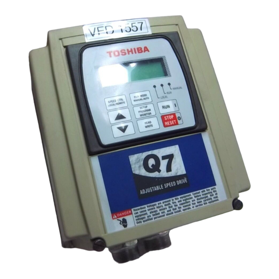
Page 25: Q7 Keypad And Integrated Enclosure Control Panel Information
Q7 Keypad and Integrated Enclosure Control Panel Information Q7 Keypad Features The Q7 Keypad is comprised of an LCD display, three system status LEDs, and eight keys. These items are described below and their locations are provided in Figure 9 on pg. -
Page 26: Q7 Keypad Operation
Monitor (SPM) Key Q7 Keypad Operation The Q7 Keypad is the primary input/output device for the user. The Q7 Keypad may be used to monitor system functions, input data into the system, or perform diagnostics. Press the SPM key to loop through the root menu selections. Use the R/W key and the Up and Down... -
Page 27: Q7 Integrated Enclosure Control Panel Features
Q7 Integrated Enclosure Control Panel Features There are three types of Q7 Integrated Enclosure control panels available. The panel used will be a function of the system features available for a given system. Two of the panels provide the user with control and monitoring features and one is used as a cover for an unused panel mounting hole and has no active features. - Page 28 Test Mode switch closes the 1M contactor (via K1) to test the ASD section of the system without providing an output to the connected motor. Test LED (LED 1) — On during Test Mode operation. Q7 ASD Installation and Operation Manual...
-
Page 29: System Configuration And Menu Options
System Configuration and Menu Options Root Menus The SPM key accesses the (active) root menus of the Q7: the Output Frequency, Setup, Program, Monitor, and the Alarm and Fault screens (if active). From either mode, press the SPM key to loop... -
Page 30: Monitor Mode
Output Current — Shows the instantaneous output current as a percentage of the rating of the ASD or as a current (see Units for V/I on pg. 47). Frequency Command — Displays the current frequency command. Q7 ASD Installation and Operation Manual... -
Page 31: Menu Navigation
RX2 Speed Freq #1 Maximum Voltage #3 RX2 Speed Ref #1 Base Frequency 3 Electronic Thermal RX Torque Ref #2 Protection #2 RX Torque Ref #1 Torque Boost #2 RX Speed Freq #2 Maximum Voltage #2 Q7 ASD Installation and Operation Manual... - Page 32 Station (Press SPM key to exit menu items) ASD Number Transmit Address Ext Comm Cfg #8 Receive Address Comm. Communications Ext Comm Cfg #7 Settings Speed 2 Communications Ext Comm Cfg #6 Reference 2 Q7 ASD Installation and Operation Manual...
- Page 33 (Press SPM key to exit Delay Filter Cooling Fan Control menu items) Differential Gain Trip Save Integral Gain Soft Stall Selection Motor 150% Run Proportional Gain Time Setting Overload Reduction Frequency Undervoltage Time Undervoltage Trip Q7 ASD Installation and Operation Manual...
- Page 34 PS Speed Mode 8 End Frequency access subsequent PS Speed Mode 7 menu items) PS Speed Mode 6 (Press SPM key to PS Speed Mode 5 exit menu items) PS Speed Mode 4 PS Speed Mode 3 Q7 ASD Installation and Operation Manual...
- Page 35 Deceleration #2 Time items) OUT2 Terminal Acceleration #2 Time Electronic Thermal (Press Up/Down Protection #2 Arrow key to access Torque Boost #2 subsequent menu items) Maximum Voltage #2 (Press SPM key to exit menu items) Q7 ASD Installation and Operation Manual...
- Page 36 Monitor V/f Pattern key to access subsequent screen) Lower Limit menu items) Frequency (Press SPM key to exit Upper Limit Frequency menu items) Disable F/R Run Maximum Voltage #1 Voltage Compensation Base Frequency 1 Q7 ASD Installation and Operation Manual...
- Page 37 Kilowatt Hours Output Power Input Power ASD Load Motor Load ASD Overload Ratio Motor Overload Ratio PID Feedback Post Compensation Frequency Run Time Output Terminals Input Terminals Output Voltage DC Voltage Output Current Frequency Command Q7 ASD Installation and Operation Manual...
-
Page 38: System Operation
Figure 11 on pg. For a complete listing of the Program menu and Setup menu items, see the section titled Menu Navigation on pg. 25. The menu items are listed and mapped for convenience. Q7 ASD Installation and Operation Manual... -
Page 39: Search (For Default Setting Changes)
Some parameters use the unsaved changed value until the ASD is Reset or powered off (e.g., Frequency Command, Accel/Decel, etc.). Pressing the SPM key when done searching or when halted at a changed parameter returns the system to the primary menu loop. Q7 ASD Installation and Operation Manual... -
Page 40: Parameter Descriptions
With the drive running at a known frequency, adjust this parameter until the AM Terminal Adjustment running frequency produces the desired DC level output at the AM terminal. Q7 ASD Installation and Operation Manual... - Page 41 Defines the protocol for system information that is transferred via the Communication Data Type communications channel. The value that is associated with the frequency setting Communications Speed Communications Reference 1 The value that is associated with the frequency setting Communications Speed Communications Reference 2 Q7 ASD Installation and Operation Manual...
- Page 42 Version of the CPU. This function is used to prevent normal operation while a damper is closed. See Damper Control Q7 Integrated Enclosure Theory of Operation on pg. 16 for further information on this function. This screen is used to input the electrical capacity (kW) of the Dynamic Braking Resistor.
- Page 43 Sets a multiplication factor to be applied to the programmed frequency as a Frequency Multiplier modifier. F Terminal Multifunctional programmable discrete input. Input Feedback Select Establishes the source of the feedback for the ASD. Input Power Displays the input power in kW. Q7 ASD Installation and Operation Manual...
- Page 44 This setting determines the maximum value of the output voltage of the drive. This setting determines the maximum value of the output voltage of the drive for Maximum Voltage #2 the #2 motor when using a multiple-profile configuration. Q7 ASD Installation and Operation Manual...
- Page 45 This setting delays the On response-time of the OUT1 terminal to an input OUT1 On Delay command. OUT2 Terminal Multifunctional programmable discrete output. This setting delays the Off response-time of the OUT2 terminal to an input OUT2 Off Delay change. Q7 ASD Installation and Operation Manual...
- Page 46 This setting determines the amount of time that the overtorque condition may Overtorque Detect Time exceed the tripping threshold level before a trip occurs. This setting determines the torque threshold level that is used as a setpoint for Overtorque Level Negative overtorque tripping during regeneration. Q7 ASD Installation and Operation Manual...
- Page 47 PG Speed Freq #1 (frequency). This parameter sets PG Speed Freq #2 (frequency) and is the frequency that is PG Speed Freq #2 associated with the pulse count setting PG Speed Ref #2 (%). Q7 ASD Installation and Operation Manual...
- Page 48 Same as PS Speed Mode 1. PS Speed Mode 11 Same as PS Speed Mode 1. PS Speed Mode 12 Same as PS Speed Mode 1. PS Speed Mode 13 Same as PS Speed Mode 1. Q7 ASD Installation and Operation Manual...
- Page 49 Sets the information transfer rate for RS485 communications. In a master/follower configuration, this setting determines the output parameter RS485 Master Output of the master ASD that will be used to control the applicable follower ASDs. Q7 ASD Installation and Operation Manual...
- Page 50 RX2 Speed Freq #2 (frequency). S1 Terminal Multifunctional programmable discrete input. Multifunctional programmable discrete input (Multicom expansion card S10 Terminal required). Multifunctional programmable discrete input (Multicom expansion card S11 Terminal required). Q7 ASD Installation and Operation Manual...
- Page 51 Sets the lower deviation limit of the output frequency while operating using PG Speed Drop Frequency feedback. In a multiple-ASD configuration, this setting determines the memory location of Speed Reference Address the speed reference. Q7 ASD Installation and Operation Manual...
- Page 52 This setting establishes the low end of the DC bus voltage threshold that, once Undervoltage Stall Level exceeded, will cause an Undervoltage Stall. This parameter sets the time that the undervoltage condition must exist to cause Undervoltage Time an Undervoltage Trip. Q7 ASD Installation and Operation Manual...
- Page 53 The user-set frequency that is associated with the voltage or current input level of VI/II Speed Ref #2 the VI/II Speed Reference #2 setting. This function provides a varying degree of output waveform adjustment that Voltage Compensation compensates for changes in the input voltage. Q7 ASD Installation and Operation Manual...
-
Page 54: Enclosure Dimensions And Conduit Plate Information
Q7 Part Numbering Convention. Note: The Type 1 enclosed versions of the Q7 ASD meet or exceed the specification UL 1995, the Standard for Heating and Cooling Equipment, and complies with the applicable requirements for installation in a compartment handling conditioned air. -
Page 55: Enclosure Dimensions/Weights
(lbs.) Bottom 2010 2015 2025 2035 2055 2080 4015 4025 4035 4055 55295 4080 4110 4160 6015 6025 6035 6060 6080 6120 6160 Figure 14. Conduit Plate 55295. Also see Conduit Box 53354 on Q7 ASD Installation and Operation Manual... - Page 56 Table 5. VT130-Series Enclosure Size 2. Conduit Model Plate Number Number VT130Q7U Bottom 2110 2160 2220 2270 2330 2400 4220 4270 4330 4400 55361 4500 4600 6220 6270 6330 6400 6500 6600 6750 Figure 15. Conduit Plate 55361. Q7 ASD Installation and Operation Manual...
- Page 57 Table 6. VT130-Series Enclosure Size 3. Conduit Model Plate Number Number VT130Q7U Bottom 4750 410K 55547 412K 610K Figure 16. Conduit Plate 55547. Q7 ASD Installation and Operation Manual...
- Page 58 Table 7. VT130-Series Enclosure Size 4. Conduit Plate Model Number Number VT130Q7U Bottom 415K 420K 612K 49900 49468 615K 620K Figure 17. Conduit Plates 49900 and 49648. Q7 ASD Installation and Operation Manual...
- Page 59 Table 8. VT130-Series Enclosure Size 5. Conduit Plate Model Number Number VT130Q7U Bottom Top 425K 430K 435K 54086 625K 630K 635K Figure 18. Conduit Plate 54086. Q7 ASD Installation and Operation Manual...
- Page 60 Table 9. Q7 Flow Series Integrated Enclosure Size 1. Model Number Q7 2010 2015 2025 2035 2055 2080 4015 4025 4035 4055 4080 4110 4160 6015 6025 6035 6060 6080 6120 6160 Q7 ASD Installation and Operation Manual...
- Page 61 Table 10. Q7 Flow Series Integrated Enclosure Size 2. Model Number Q7 2110 2160 2220 2270 2330 2400 4220 4270 4330 4400 4500 4600 6220 6270 6330 6400 6500 6600 6750 Q7 ASD Installation and Operation Manual...
-
Page 62: Conduit Box Information
Conduit Box Information The conduit plate information provided below is for the VT130 Series Q7 ASDs listed in Table 4 on page The Conduit Box (P/N ASD-Conduit-1) may be used when more room is required at the ASD conduit connection point for the stand-alone devices. This option makes adding and removing conduit easier and quicker. -
Page 63: Cable/Terminal Specifications
The following ratings are guidelines and shall not be the sole determining factor of the lug or wire size used with the Q7 ASD. Application-specific applicables, wire insulation type, conductor material, and local and regional regulations are but a few of the considerations when selecting the actual lug and wire type to be used with the ASD. - Page 64 Table 12. Q7 ASD 460 Volt Drive Cable/Terminal Specifications. Typical Cable Size (AWG) Lug Size Circuit Model No. Breaker Q7 or Input/Output Rating AM, FM, and II Control Terminal ASD Input/Output Power VT130Q7U Power Wire (Amps) Terminals Strip Lug Wire Capacity...
- Page 65 Table 13. Q7 ASD 600 Volt Drive Cable/Terminal Specifications. Typical Cable Size (AWG) Lug Size Circuit Model No. Breaker Q7 or Input/Output Rating AM, FM, and II Control Terminal ASD Input/Output Power Power Wire VT130Q7U Terminals Strip Lug Wire Capacity...
-
Page 66: Current/Voltage Specifications
143.0 A 2500 50.0 50.0/37.3 156.0 171.6 A 2600 60.0 60.0/44.7 192.0 211.0 A 2750 75.0 75.0/56.0 248.0 272.8 A 210K 100.0/74.6 312.0 343.2 A 212K 125.0/93.2 370.0 407.0 A 215K 150.0/112.0 415.0 456.5 A Q7 ASD Installation and Operation Manual... - Page 67 190.0 A 209.0 A 420K 200/150 240.0 A 264.0 A 425K 250/185 302.0 A 332.2 A 430K 300/220 370.0 A 407.0 A 435K 350/280 450.0 A 495.0 A 440K 400/298 492.0 A 541.2 A Q7 ASD Installation and Operation Manual...
- Page 68 125.0 A 137.5 A 615K 150/110 150.0 A 165.0 A 620K 200/150 200.0 A 220.0 A 625K 250/185 250.0 A 275.0 A 630K 300/220 300.0 A 330.0 A 635K 350/261 336.0 A 369.6 A Q7 ASD Installation and Operation Manual...
- Page 69 Direction, 24, 36 Disable F/R Run, 36 Cable/Terminal Specifications, 57 Disposal, 4 CC, 14 DRA, 14 change direction, 32 DRA to DRB, 6 Changed From Default Parameters, 35 CIA to CIB, 6 Dynamic Braking, 36 Q7 ASD Installation and Operation Manual...
- Page 70 Low Current Trip, 38 Lower Limit Frequency, 38 Lug Size, 57 I/II Frequency #2, 47 I/O and Control, 14 II, 14 Important Notice, 3 Main EEPROM Version, 38 Input Feedback Select, 37 Maintenance Precautions, 3 Q7 ASD Installation and Operation Manual...
- Page 71 Preset Speed #14, 42 OUT6 Off Delay, 40 Preset Speed #15, 42 OUT6 On Delay, 40 Preset Speed #2, 42 OUT7, 40 Preset Speed #3, 42 OUT7 Off Delay, 40 Preset Speed #4, 42 Q7 ASD Installation and Operation Manual...
- Page 72 PWM Carrier Frequency, 43 S20 Reset, 45 S3, 14, 45 S4, 14, 45 S4 to CC, 6 S5, 45 Q7 Integrated Enclosure Theory of Operation, 16 S5–S16 Delay, 45 Qualified Personnel, 1 S6, 45 S7, 45 S8, 45 S9, 45...
- Page 73 Torque Boost #4, 46 VI/II Input, 24, 47 Torque Reference Address, 46 Torque Reference Station, 46 VI/II Speed Reference #1, 47 Transmit Address, 46 VI/II Speed Reference #2, 47 Trip Code, 24, 46 Voltage Compensation, 47 Q7 ASD Installation and Operation Manual...