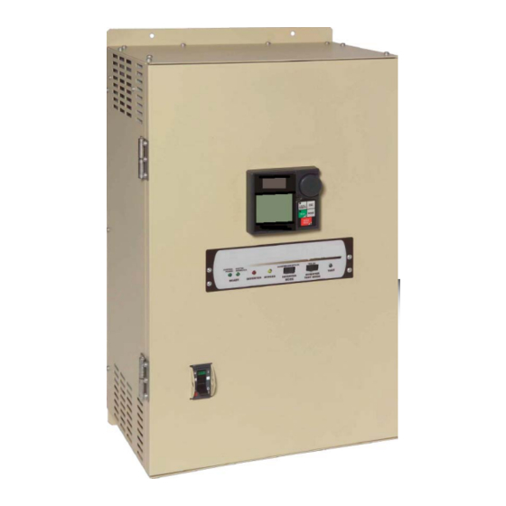
Toshiba Q9 Plus Installation & Operation Manual
Bypass asd/bypass box
Hide thumbs
Also See for Q9 Plus:
- Quick start manual (108 pages) ,
- Installation & operation manual (434 pages)

Related Manuals for Toshiba Q9 Plus


Summary of Contents for Toshiba Q9 Plus
- Page 1 June, 2013 Q9 Plus Bypass ASD/Bypass Box & O NSTALLATION PERATION ANUAL DN: 68251-000 Phone: 800.894.0412 - Fax: 888.723.4773 - Web: www.clrwtr.com - Email: info@clrwtr.com...
- Page 2 Q9 Plus Bypass ASD/ Q9 Plus Bypass Box Installation & Operation Manual Document Number: 68251-000 June, 2013 Phone: 800.894.0412 - Fax: 888.723.4773 - Web: www.clrwtr.com - Email: info@clrwtr.com...
- Page 3 This manual has been prepared to enable installers, users, and maintenance personnel to maximize the abilities of the Q9 Plus Bypass ASD/Q9 Plus Bypass Box. With this in mind, use this manual to develop a system familiarity before attempting to install or operate the device. This manual may also be used as a reference guide or for training.
-
Page 4: Important Notice
The sales contract contains the entire obligation of Toshiba International Corporation. The warranty contained in the contract between the parties is the sole warranty of Toshiba International Corporation and any statements contained herein do not create new warranties or modify the existing warranty. -
Page 5: About This Manual
Read the manual completely before installing, operating, performing maintenance, or disposing of this equipment. Throughout this manual the term Q9 Plus Bypass ASD will be used to describe the Q9 Plus ASD and its accompanying bypass circuitry all within one enclosure. The term Q9 Plus Bypass Box is used to describe the bypass box alone. - Page 6 Q9 Plus Bypass ASD/Q9 Plus Bypass Box Please complete the Warranty Card supplied with your system and return it to Toshiba International Corporation by prepaid mail. This will activate the 12-month warranty from the date of installation; but, shall not exceed 18 months from the shipping date.
-
Page 7: Table Of Contents
Motor Circuit Protector Adjustment and Setting ............18 Overload Circuit Protector Adjustment and Setting ............19 Installation and Connections ....................20 Installation Notes ......................20 Input Power ........................20 Q9 Plus Bypass ASD/Bypass Box Installation and Operation Manual Phone: 800.894.0412 - Fax: 888.723.4773 - Web: www.clrwtr.com - Email: info@clrwtr.com... - Page 8 Panel Item Descriptions ....................35 Part Numbering Convention and System Components .............37 Enclosure Dimensions/Weights ....................39 Cable/Terminal Specifications ....................43 Current/Voltage Specifications .....................45 Q9 Plus Bypass ASD/Bypass Box Installation and Operation Manual Phone: 800.894.0412 - Fax: 888.723.4773 - Web: www.clrwtr.com - Email: info@clrwtr.com...
-
Page 9: General Safety Information
The word CAUTION without the safety alert symbol indicates that a potentially hazardous situation exists that, if not avoided or if instructions are not followed precisely, may result in equipment and property damage. Q9 Plus Bypass ASD/Bypass Box Installation and Operation Manual Phone: 800.894.0412 - Fax: 888.723.4773 - Web: www.clrwtr.com - Email: info@clrwtr.com... -
Page 10: Special Symbols
• Have carefully read the entire manual. • Be familiar with the construction and function of the Q9 Plus Bypass ASD/Q9 Plus Bypass Box, the equipment being driven, and the hazards involved. • Be able to recognize and properly address hazards associated with the application of motor-driven equipment. -
Page 11: Equipment Inspection
Store in a cool, clean, and dry location. Avoid storage locations with extreme temperatures, rapid temperature changes, high humidity, moisture, dust, corrosive gases, or metal particles. • The storage temperature range of the Q9 Plus Bypass ASD/Q9 Plus Bypass Box is -13° to 149° F (-25° to 65° C). •... -
Page 12: Installation Precautions
(equipment damage or injury). • DO NOT mount the Q9 Plus Bypass ASD/Q9 Plus Bypass Box in a location that would allow it to be exposed to flammable chemicals or gases, water, solvents, explosive/corrosive mists or gases, or other fluids. -
Page 13: Conductor Routing And Grounding Precautions
Ensure that the three-phase input power is NOT connected to the output of the Q9 Plus Bypass ASD/Q9 Plus Bypass Box. This will damage the system and may cause injury to personnel. • DO NOT install the Q9 Plus Bypass ASD/Q9 Plus Bypass Box if it is damaged or if it is missing any component(s). •... -
Page 14: Protection
If using multiple motors, provide separate overload protection for each motor, and use V/f control. • It is the responsibility of the person installing the Q9 Plus Bypass ASD/Q9 Plus Bypass Box or the electrical maintenance personnel to setup the Emergency Off braking system of the Q9 Plus Bypass ASD/Q9 Plus Bypass Box. -
Page 15: System Integration Precautions
Customer Support Center for application-specific information or for training support. • The TIC Q9 Plus Bypass ASD/Q9 Plus Bypass Box is part of a larger system, and the safe operation of the Q9 Plus Bypass ASD/Q9 Plus Bypass Box will depend on observing certain precautions and performing proper system integration. -
Page 16: System Setup Requirements
System Setup Requirements • When using the Q9 Plus Bypass ASD/Q9 Plus Bypass Box as an integral part of a larger system, it is the responsibility of the Q9 Plus Bypass ASD/Q9 Plus Bypass Box installer or maintenance personnel to ensure that there is a fail-safe in place (i.e., an arrangement designed to switch the system to a safe condition if there is a fault or failure). -
Page 17: Operational And Maintenance Precautions
• Turn the power on only after attaching (or closing) the front cover. DO NOT open or remove the front cover or any of the enclosure panels of the Q9 Plus Bypass ASD/Q9 Plus Bypass Box during normal operation. •... - Page 18 • The Q9 Plus Bypass ASD/Q9 Plus Bypass Box is designed to operate NEMA B motors. Consult with the TIC Customer Support Center before using the Q9 Plus Bypass ASD/Q9 Plus Bypass Box for special applications such as with an explosion-proof motor or applications with a piston load.
-
Page 19: Ce Compliance Requirements
(EMC). The following instructions provide a means of compliance for the Q9 Plus Bypass ASD/Q9 Plus Bypass Box. A Technical Construction File (TCF) indicates the rationale used to declare compliance and is on file at Toshiba International Corporation, Houston, Texas, U.S.A. -
Page 20: Emc Compliant Installation Guidelines
EMC Compliant Installation Guidelines The Q9 Plus Bypass ASD/Q9 Plus Bypass Box shall be installed in accordance with the following guidelines. Filtering — An input filter shall be used with the ASD. A Schaffner FN258 series input filter of the appropriate rating shall be used and mounted adjacent to the ASD. -
Page 21: Theory Of Operation
Theory of Operation The Q9 Plus Bypass ASD/Q9 Plus Bypass Box system is available in three primary configurations. The system configuration type is defined by the suffix A, C, or E as shown in the part numbering convention on The description below targets the E configuration. System operation for the A and C types differ from the E type where the referenced function is not supported by the A or C typeform. -
Page 22: Stage 4 Function
(reversible means that only the opposite function is available once reaching the fully opened or closed position). Q9 Plus Bypass ASD/Bypass Box Installation and Operation Manual Phone: 800.894.0412 - Fax: 888.723.4773 - Web: www.clrwtr.com - Email: info@clrwtr.com... - Page 23 Figure 1. Simplified Depiction (Ladder Logic) of the Q9 Plus Bypass ASD Bypass Operation See the section titled Theory of Operation on pg. 13 for a description of the simplified depiction. Q9 Plus Bypass ASD/Bypass Box Installation and Operation Manual...
-
Page 24: System Protection
The short-circuit protection, which is provided by hardware and software, disables the system in the event of a fault. The installer is to provide input fuses for the 230-volt Q9 Plus ASDs. The 460-volt Q9 Plus ASDs are equipped with internal primary power input fuses as a standard feature. -
Page 25: Motor Protection
The MCP that is used on the L1, L2, and L3 input power lines has a Shunt Trip feature that may be used to further enhance the system protection function of the Q9 Plus Bypass ASD/Q9 Plus Bypass Box. The Shunt Trip feature may be connected such that the L1, L2, and L3 MCP may be opened by a state change of the LS switch. -
Page 26: Motor Circuit Protector Adjustment And Setting
ONLY (see Qualified Personnel on pg. Figure 3. MCP Adjustment. Set to minimum at the factory. Application-specific adjustment is required. Q9 Plus Bypass ASD/Bypass Box Installation and Operation Manual Phone: 800.894.0412 - Fax: 888.723.4773 - Web: www.clrwtr.com - Email: info@clrwtr.com... -
Page 27: Overload Circuit Protector Adjustment And Setting
Both contacts change states during an overload trip. The contacts may be used with ancillary circuitry to annunciate an overload trip or to control other system features. Q9 Plus Bypass ASD/Bypass Box Installation and Operation Manual Phone: 800.894.0412 - Fax: 888.723.4773 - Web: www.clrwtr.com - Email: info@clrwtr.com... -
Page 28: Installation And Connections
When a brake-equipped motor is connected to the Q9 Plus Bypass ASD/Q9 Plus Bypass Box, it is possible that the brake may not release at startup because of insufficient voltage. To avoid this condition, DO NOT connect the brake or the brake contactor to the output of the Q9 Plus Bypass ASD/ Q9 Plus Bypass Box. -
Page 29: Mounting And Connections
Mechanical enclosure differences are specified as required. The Q9 Plus Bypass ASD/Q9 Plus Bypass Box may be set up initially by performing a few simple system configuration connections and settings. To operate properly, the Q9 Plus Bypass ASD/Q9 Plus Bypass Box must be securely mounted and connected to a power source (three-phase AC input at the L1, L2, and L3 terminals). -
Page 30: Mounting The Bypass Box
The Q9 Plus ASD is then installed as described in the Q9 Plus ASD Installation and Operation Manual (D/N 68249). The Q9 Plus ASD is attached to the Bypass Box using the two screws of the Bypass Box wire chase resulting in the configuration shown in Figure 5 on pg. -
Page 31: Connecting The Bypass Box
Terminal Specifications on pg. Connect the Q9 Plus ASD to the Bypass Box as follows: Connect the L1, L2, and L3 terminals of the Q9 Plus ASD to the L1, L2, and L3 terminals of the Bypass Box, respectively, via terminal block PDB1. - Page 32 Figure 5. Q9 Plus ASD-to-Q9 Plus Bypass Box Typical Connection Diagram. Note: The connection diagram of this figure applies to the C and E system types. Q9 Plus Bypass ASD/Bypass Box Installation and Operation Manual Phone: 800.894.0412 - Fax: 888.723.4773 - Web: www.clrwtr.com - Email: info@clrwtr.com...
-
Page 33: Startup And Test
ASD-driven mode is consistent. • Ensure that all personnel are clear of the motor and the motor-driven equipment. Q9 Plus Bypass ASD/Bypass Box Installation and Operation Manual Phone: 800.894.0412 - Fax: 888.723.4773 - Web: www.clrwtr.com - Email: info@clrwtr.com... -
Page 34: I/O Monitoring And Control
I/O Monitoring and Control The Q9 Plus Bypass ASD/Q9 Plus Bypass Box can be controlled by several input types and combinations thereof, as well as operate within a wide range of voltage levels. This section discusses the control methods and supported I/O functions. -
Page 35: I/O Terminal Descriptions
CC to this terminal (Sink mode). The function of this input as Preset Speed 2 is to run the motor at the Preset Speed 2 setting for the duration of the activation. This input terminal may be programmed to any of the discrete terminal functions that are listed in the Q9 Plus ASD Installation & Operation Manual. - Page 36 This function may be used to signal external equipment (e.g., activate the brake). The OUT2 contact is rated at 2A/250 VAC. See the Q9 Plus ASD Installation & Operation Manual for further information on this terminal.
- Page 37 Output Current of the Q9 Plus Bypass ASD (or the function assigned to this terminal). This output terminal may be programmed to provide an output that is a function of any of the functions listed in the Q9 Plus ASD Installation & Operation Manual.
-
Page 38: Monitoring/Control Interface
EOI. The Terminal Board also provides output signals that may be used to control ancillary devices, close/open a contact, annunciate, or monitor system variables. Connect the available input and output monitoring/control lines of the Q9 Plus Bypass ASD/Q9 Plus Bypass Box in accordance with the type of system being used as shown in Figure 8 on pg. -
Page 39: Typical Connection Diagram
Typical Connection Diagram Three expanded depictions of the Q9 Plus Bypass ASD/Q9 Plus Bypass Box systems are shown in figures 8, 9, and 10. Figure 7. Q9 Plus Bypass ASD/Q9 Plus Bypass Box Typical Connection Diagram. Note: When connecting multiple wires to the PA, PB, PC, or PO terminals, DO NOT connect a solid wire and a stranded wire to the same terminal. - Page 40 Figure 8. Q9 Plus Bypass ASD/Bypass Box-IA Typical Connection Diagram — No Bypass or Contactors. L1 L2 T1 T2 115VAC Factory- Installed PCB12 Jumpers CN1A CN2A CNCPT CNLS Optional Reactances JPDS1 OUT2A OUT2B (OUT1) CN1M L1 L2 Charge Indicator LED...
- Page 41 Figure 9. Q9 Plus Bypass ASD/Bypass Box-IC Typical Connection Diagram — Two-Contactor. Bypass. PCB11 L1 L2 TYPICAL LED CIRCUIT LED5 LED2 LED3 T1 T2 LED4 115VAC PCB12 Factory- CN1A CN2A Installed CNCPT Jumpers Optional Reactances CNLS JPDS1 L1 L2 CHARGE...
- Page 42 Figure 10. Q9 Plus Bypass ASD/Bypass Box-IE Typical Connection Diagram — Three-Contactor Bypass. Q9 Plus Bypass ASD/Bypass Box Installation and Operation Manual Phone: 800.894.0412 - Fax: 888.723.4773 - Web: www.clrwtr.com - Email: info@clrwtr.com...
-
Page 43: Control Panel Features
Panel A is used as a cover and has no active features. Panels C and E provide the user with access to the Q9 Plus Bypass ASD/Q9 Plus Bypass Box monitoring and control features. Each feature is discussed below and expanded upon in the section titled Theory of Operation on pg. - Page 44 ASD output to the connected motor. Test LED (LED 1) — ON during Inverter Test Mode operation. Q9 Plus Bypass ASD/Bypass Box Installation and Operation Manual Phone: 800.894.0412 - Fax: 888.723.4773 - Web: www.clrwtr.com - Email: info@clrwtr.com...
-
Page 45: Part Numbering Convention And System Components
Figure 13. Q9 Plus Bypass Box (only) Part Numbering Convention. Note: The Type 1 enclosed versions of the Q9 Plus Bypass ASD/Q9 Plus Bypass Box meet or exceed the specification UL 1995, the Standard for Heating and Cooling Equipment, and complies with the applicable requirements for installation in a compartment handling conditioned air. - Page 46 Figure 14. Typical Q9 Plus ASD/ Q9 Plus Bypass Box Components. Note: Size 1 shown. Q9 Plus Bypass ASD/Bypass Box Installation and Operation Manual Phone: 800.894.0412 - Fax: 888.723.4773 - Web: www.clrwtr.com - Email: info@clrwtr.com...
-
Page 47: Enclosure Dimensions/Weights
Enclosure Dimensions/Weights Table 2. Q9 Plus Bypass ASD Series Enclosure Size 1 (inches/mm). Shipping Model Weight Number Approx. (Lbs/kg.) Q9+2015 Q9+2025 Q9+2035 Q9+2055 Q9+2080 Q9+4015 95/43.1 Q9+4025 Q9+4035 Q9+4055 Q9+4080 Q9+4110 Q9+4160 Q9 Plus Bypass ASD/Bypass Box Installation and Operation Manual... - Page 48 Table 3. Q9 Plus Bypass ASD Series Enclosure Size 2 (inches/mm). Shipping Model Weight Number Approx. (Lbs/kg.) Q9+2110 Q9+2160 Q9+2220 Q9+2270 180/81.5 Q9+4220 Q9+4270 Q9+4330 Q9+4400 Q9 Plus Bypass ASD/Bypass Box Installation and Operation Manual Phone: 800.894.0412 - Fax: 888.723.4773 - Web: www.clrwtr.com - Email: info@clrwtr.com...
- Page 49 Table 4. Q9 Plus Bypass ASD Series Enclosure Size 3 (inches/mm). Shipping Weight Model Number Approx. (Lbs/kg.) 182/82.6 Q9+2330 Q9+2400 Q9+4500 282/128 Q9+4600 Q9+4750 324/147 Q9+410K Q9+412K 356/161.5 Model Dimension Dimension Number 2330(E) 54.4/1382 53.13/1350 2330(E)(R) 59.75/1518 58.5/1486 2400(E) 2400(E)(R) 64.88/1648 63.63/1616...
- Page 50 Table 5. Q9 Plus Bypass Box Series Enclosure Size 3 (inches/mm). Shipping Model Weight — ASD SOLD SEPARATELY FOR THIS TYPEFORM — Number Approx. (Lbs/kg.) BYP2-100 127/57.6 BYP2-125 BYP4-070 102/46.3 BYP4-080 127/57.6 BYP4-100 BYP4-125 142/64.4 BYP4-160 174/78.9 Model Number BYP2-100-EX 32.10/815 30.12/765 31.23/793...
-
Page 51: Cable/Terminal Specifications
Note: Use only 75° C copper wire/cable for motor and power connections. Table 6. Q9 Plus Bypass ASD/Q9 Plus Bypass Box 230- and 460-Volt Drive Cable/Terminal Specifications. Typical Wire/Cable Size Lug Size/Wire Capacity AWG/kcmil Model No. - Page 52 Table 6. Q9 Plus Bypass ASD/Q9 Plus Bypass Box 230- and 460-Volt Drive Cable/Terminal Specifications. Typical Wire/Cable Size Lug Size/Wire Capacity AWG/kcmil Model No. Rating (Amps) Input/Output Circuit Breaker TB2 – TB6 OL Relay Output Power Input/Output Input Q9+4600 –...
-
Page 53: Current/Voltage Specifications
Q9+4330 40.0 A 44.0 A Q9+4400 52.0 A 57.2 A Q9+4500 65.0 A 71.5 A Q9+4600 77.0 A 84.7 A Q9 Plus Bypass ASD/Bypass Box Installation and Operation Manual Phone: 800.894.0412 - Fax: 888.723.4773 - Web: www.clrwtr.com - Email: info@clrwtr.com... - Page 54 84.7 A BYP4-100 Q9+4750 96.0 A 105.6 A BYP4-125 Q9+410K 124.0 A 136.4 A BYP4-160 Q9+412K 156.0 A 171.6 A Q9 Plus Bypass ASD/Bypass Box Installation and Operation Manual Phone: 800.894.0412 - Fax: 888.723.4773 - Web: www.clrwtr.com - Email: info@clrwtr.com...
- Page 55 Introduction, 3 DRA, 26 INV, 14 DRA to DRB, 20 Inverter LED, 35 DRA/DRB, 28 DRA-to-DRB, 14 Inverter Mode Switch, 36 Q9 Plus Bypass ASD/Bypass Box Installation and Operation Manual Phone: 800.894.0412 - Fax: 888.723.4773 - Web: www.clrwtr.com - Email: info@clrwtr.com...
- Page 56 Q9 Plus Bypass ASD/Q9 Plus Bypass Box-C, 33 Q9 Plus Bypass ASD/Q9 Plus Bypass Box-E, 34 Q9 Plus Bypass Box Enclosure, 38 Warranty Card, 2 Q9 Plus Bypass ASD/Bypass Box Installation and Operation Manual Phone: 800.894.0412 - Fax: 888.723.4773 - Web: www.clrwtr.com - Email: info@clrwtr.com...