Toshiba Q7 Installation And Operation Manual
Hide thumbs
Also See for Q7:
- Installation and operation manual (46 pages) ,
- Installation and operation manual (73 pages)

Related Manuals for Toshiba Q7


Summary of Contents for Toshiba Q7
- Page 1 Q7 Adjustable Speed Drive Installation and Operation Manual Document Number: 57246-001 Date: June, 2005...
-
Page 2: Important Notice
Congratulations on the purchase of the new Q7 Adjustable Speed Drive (ASD). The Q7 ASD is a solid- state AC drive. The Q7 ASD is ideally suited to drive the variable torque load of an HVAC system. Toshiba’s technology, quality, and reliability enables the motor to develop high torque and provide compensation for motor slip, which results in smooth, quick starts and highly efficient operation. -
Page 3: About This Manual
About This Manual This manual was written by the Toshiba Technical Publications Group. This group is tasked with providing technical documentation for the Q7 Adjustable Speed Drive. Every effort has been made to provide accurate and concise information to you, our customer. - Page 4 Q7 Adjustable Speed Drive Please complete the Warranty Card supplied with the ASD and return it to Toshiba by prepaid mail. This will activate the 12 month warranty from the date of installation; but, shall not exceed 18 months from the shipping date.
-
Page 5: Table Of Contents
ASD Capacity ........................13 Installation and Connections ....................14 Installation Notes ......................14 Mounting the ASD ......................16 Connecting the ASD ......................16 System Grounding ..................... 16 Power Connections ....................17 Lead Length Specifications ..................18 Q7 ASD Installation and Operation Manual... -
Page 6: Table Of Contents
Viewing Trip Information ..................151 Clearing a Trip ......................151 Enclosure Dimensions and Conduit Plate Information ........... 152 Enclosure Dimensions/Weight ..................153 Conduit Box Information ....................158 Cable/Terminal Specifications .................... 159 Current/Voltage Specifications ................... 162 Q7 ASD Installation and Operation Manual... -
Page 7: General Safety Information
CAUTION The word CAUTION without the safety alert symbol indicates a potentially hazardous situation exists which, if not avoided, may result in equipment and property damage. CAUTION Q7 ASD Installation and Operation Manual... -
Page 8: Special Symbols
If the labels are damaged or if additional labels are required, contact your Toshiba sales representative for additional labels. Labels attached to the equipment are there to provide useful information or to indicate an imminently hazardous situation that may result in serious injury, severe property and equipment damage, or death if the instructions are not followed. -
Page 9: Qualified Personnel
• Keep the equipment in an upright position. • Contact your Toshiba sales representative to report discrepancies or for assistance if required. Handling and Storage • Use proper lifting techniques when moving the ASD; including properly sizing up the load, getting assistance, and using a forklift if required. -
Page 10: Disposal
Installation and Connections on pg. 14 for further information on ventilation requirements. • The ambient operating temperature range of the Q7 ASD is 14° to 104° F (-10 to 40° C). • See the section titled Installation and Connections on pg. 14 for additional information on installing the drive. -
Page 11: Mounting Requirements
(i.e., place U1, V1, and W1 in one conduit and U2, V2, and W2 in another) (refer to NEC Article 300.20 and Article 310.4). National and local electrical codes should be referenced if Q7 ASD Installation and Operation Manual... -
Page 12: Protection
Please contact your Toshiba sales representative for application-specific information or for training support. • The Toshiba ASD is part of a larger system and the safe operation of the ASD will depend on observing certain precautions and performing proper system integration. •... -
Page 13: Personnel Protection
ASD output terminals (U, V, W). • Power factor improvement capacitors or surge absorbers must not be installed on the output of the ASD. Q7 ASD Installation and Operation Manual... -
Page 14: Operational And Maintenance Precautions
Turn the power on only after attaching (or closing) the front cover and Do Not remove the front cover of the ASD when the power is on. • Do Not attempt to disassemble, modify, or repair the ASD. Call your Toshiba sales representative for repair information. •... -
Page 15: Service Life Information
Service Life Information Part Name Service Life Remarks Large Capacity Electrolytic When not used for long periods, 5 Years Capacitor charge semi-annually. Cooling Fan 26,000 Hours CN Connectors 100 Connects/Disconnects On-board Relays 500,000 Actuations Q7 ASD Installation and Operation Manual... -
Page 16: Ce Compliance Requirements
European market is required to comply to the European Community directive on electromagnetic compatibility (EMC). The following instructions provide a means of compliance for the Q7 ASD. A Technical Construction File (TFC) indicates the rationale used to declare compliance and is on file at Toshiba International Corporation, Houston, Texas U.S.A. - Page 17 ASD shall also be screened. This screen shall connect to both the ASD enclosure and the resistor enclosure. See the Q7 Filter Selection below for the recommended input filters for a given typeform. Table 1.
-
Page 18: Motor Characteristics
ASD, rather than directly from commercial power. Overload Protection Adjustment The Q7 ASD software monitors the output current of the system and determines when an overload condition occurs. The overload current level is a percentage of the rating of the motor. This function protects the motor from overload. -
Page 19: Motor Braking
ASD Capacity The Q7 ASD must not be used with a motor that has a significantly larger capacity, even if the motor is operated under a small load. An ASD being used in this way will be susceptible to a high-output peak current which may result in nuisance tripping. -
Page 20: Installation And Connections
Installation and Connections The Q7 Adjustable Speed Drive may be set up initially by performing a few simple configuration settings. To operate properly, the ASD must be securely mounted and connected to a power source (3- phase AC input at the L1/R, L2/S, and L3/T terminals). The control terminals of the ASD may be used... - Page 21 All Q7 ASDs are equipped with internal DC bus fuses. However, not all Q7 ASDs are equipped with internal primary power input fuses (HP dependent). When connecting two or more drives that have no...
-
Page 22: Mounting The Asd
ASD. The ambient temperature rating for the Q7 ASD is from 14 to 104° F (-10 to 40° C). The process of converting AC to DC, and then back to AC produces heat. During normal ASD operation, up to 5% of the input energy to the ASD may be dissipated as heat. -
Page 23: Power Connections
For 600 volt ASDs, the 15 HP or less ASDs (P/N VT130Q7U6015 – 6160) require a class-J fuse rated at 600 Volts/30 A. On some Q7 devices 12-Pulse operation is available. A phase-shifting transformer must be supplied by the user when configured for 12-pulse operation. -
Page 24: Lead Length Specifications
≥ 5 kHz 100 feet Note: Contact Toshiba for application assistance when using lead lengths in excess of those listed. Exceeding the peak voltage rating or the allowable thermal rise time of the motor insulation will reduce the life expectancy of the motor. -
Page 25: I/O And Control
I/O and Control The Q7 ASD can be controlled by several input types and combinations thereof, as well as operate within a wide range of output frequency and voltage levels. This section describes the ASD control methods and supported I/O functions. -
Page 26: I/O Terminal Descriptions
This input terminal may be programmed to control the speed or torque of the motor and may not be used when using the VI input. Also, the gain and bias of this terminal may be adjusted. Q7 ASD Installation and Operation Manual... - Page 27 CC — Control common (Do Not connect to Earth Gnd). Figure 5. FLA, FLB, and FLC switching contacts shown in the de-energized state. Note: The relay is shown in the Faulted or de-energized condition. During normal system operation the relay connection is FLC-to-FLA. Q7 ASD Installation and Operation Manual...
- Page 28 SW1 and SW2. II Terminals Shown below are the TB1 input and output terminals of the Control Terminal Strip PCB. For further information on these terminals see OUT1 OUT2 Q7 ASD Installation and Operation Manual...
-
Page 29: Q7 Asd Control
Q7 ASD Control The Control PCB (P/N 56000) serves as the primary control source for the Q7 ASD and receives input from the Control Terminal Strip PCB, an Option Card, RS232/485 Communications, or the Q7 ASD Keypad. The Control PCB has been enhanced to support two new functions: Multiple Protocol Communications and the ability to communicate in either half- or full-duplex modes. -
Page 30: Cnu1 And Cnu2 Pinout
CN7 connects to CN7A of the Control Terminal Strip PCBA. Table 4. CN7 pinout assignments. Programmable terminals are listed as their default settings. Pin Number Function Pin Number Function *OUT1 *OUT2 — — Note: * Open collector outputs. Q7 ASD Installation and Operation Manual... -
Page 31: I/O Circuit Configurations
Figure 10. RX Input. Figure 11. VI/II Input. Figure 12. P24 Output. Figure 13. PP Output. Figure 14. OUT1/OUT2 Output. Figure 15. FP Output. Figure 16. AM/FM Output. Figure 17. Fault Relay (active fault). Q7 ASD Installation and Operation Manual... -
Page 32: Typical Connection Diagram
Typical Connection Diagram Figure 18. Q7 ASD typical connection diagram. Note: When connecting multiple wires to the PA, PB, PC, or PO terminals, do not connect a solid wire and a stranded wire to the same terminal. Q7 ASD Installation and Operation Manual... -
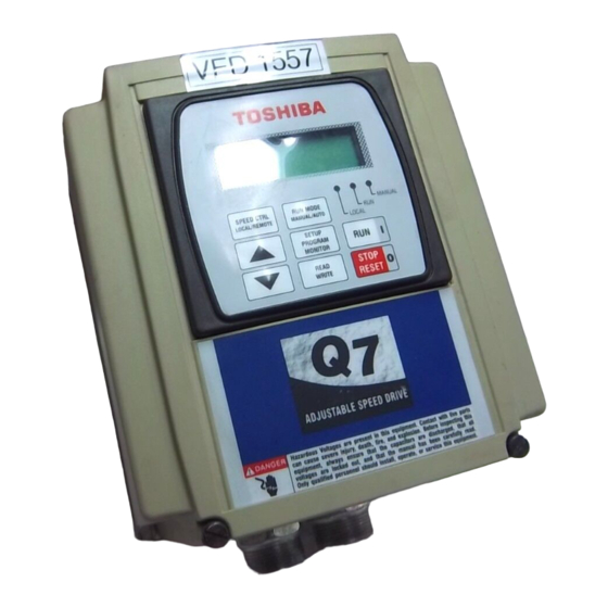
Page 33: Q7 Asd Keypad
Q7 ASD Keypad Q7 Keypad Features The Q7 Keypad is comprised of an LCD display, three system status LEDs, and eight keys. These items are described below and their locations are provided in Figure 19 on pg. The keypad may be mounted remotely. See pg. -
Page 34: Keypad Operation
Monitor (SPM) Key Keypad Operation The Q7 Keypad is the primary input/output device for the user. The Q7 Keypad may be used to monitor system functions, input data into the system, or perform diagnostics. Press the SPM key to loop through the root menu selections. Use the R/W key and the Up and Down... -
Page 35: Keypad Remote Mounting
Keypad Remote Mounting The Q7 ASD may be controlled from a remotely-mounted keypad. For safety and application-specific reasons, some ASD installations will warrant that the operator not be in the vicinity during operation or that the keypad not be attached to the ASD housing. The keypad may be mounted either with or without the optional Remote Mounting Kit (P/N ASD-MTG-KIT). -
Page 36: Keypad Remote Mounting W/O The Asd-Mtg-Kit
Attach and secure the keypad to the front side of the Bezel plate using the four 6-32 x 5/16” pan head screws, #6 split lock washers, and the #6 flat washers. Connect the extension cable. Q7 ASD Installation and Operation Manual... - Page 37 CAUTION: Failure to use the correct hardware may result in damage to the outer surface of the keypad panel and/or improper seating of the panel to the bezel plate. Use caution when mounting the keypad assembly to ensure that the internal thread clearance is maintained. Correct Incorrect Q7 ASD Installation and Operation Manual...
-
Page 38: System Operation
Figure 24 on pg. For a complete listing of the Program menu and Setup menu items, see the section titled Menu Navigation on pg. 36. The menu items are mapped for convenience. Q7 ASD Installation and Operation Manual... -
Page 39: Search (For Default Setting Changes)
Some parameters use the unsaved changed value until the ASD is Reset or powered off (e.g., Frequency Command, Accel/Decel, etc.). Pressing the SPM key when done searching or when halted at a changed parameter returns the system to the primary menu loop. Q7 ASD Installation and Operation Manual... -
Page 40: System Configuration And Menu Options
System Configuration and Menu Options Root Menus The SPM key accesses the (active) root menus of the Q7: the Output Frequency, Setup, Program, Monitor, and the Alarm and Fault screens (if active). From either mode, press the SPM key to loop... -
Page 41: Monitor Mode
Output Current — Shows the instantaneous output current as a percentage of the rating of the ASD or as a current (see Units for Voltage and Current on pg. 125). Frequency Command — Displays the current frequency command. Q7 ASD Installation and Operation Manual... -
Page 42: Menu Navigation
Menu Navigation Listed below are the mapped menu items of the Q7 ASD. Q7 ASD Menu Items Primary Menu Menu Item Sub-menu Items Primary Menu Menu Item Sub-menu Items Output Displays output frequency. Base Frequency 2 Program Fundamental Frequency Press Up/Down Arrow key to change setting. - Page 43 Arrow key to change OUT2 On Delay Wait Time accessed menu item. Commercial Power Press SPM key to OUT2 Off Delay Switching Freq. Hold exit. Time FL On Delay FL Off Delay OUT4 On Delay Q7 ASD Installation and Operation Manual...
- Page 44 Motor 150% Run PS Speed Mode 13 Time PS Speed Mode 14 Soft Stall (Select) PS Speed Mode 15 Trip Save Cooling Fan Control Run Time Alarm Setting Output Phase Loss Detection Low Current Trip Q7 ASD Installation and Operation Manual...
- Page 45 #4 Scan Receive (access method 4–20 mA Speed same as Protection) #5 Scan Receive Reference PG Number of Pulses #6 Scan Receive PG Input Phases #1 Scan Transmit PG Detect Selection #2 Scan Transmit Q7 ASD Installation and Operation Manual...
- Page 46 Arrow key to change Frequency Display accessed menu item. Motor Poles Resolution Accel/Decel Display Press SPM key to exit. Motor Capacity Resolution Units for Voltage Motor Type and Current User Unit #1 Autotune Enable Q7 ASD Installation and Operation Manual...
- Page 47 4–20 mA Loss Selection 4–20 mA Speed BIN Speed Reference #1 Reference Frequency Command BIN Speed Frequency #1 Panel BIN Speed Reference #2 PID Feedback BIN Speed Frequency #2 BIN Torque Reference #1 BIN Torque Reference #2 Q7 ASD Installation and Operation Manual...
- Page 48 Input Power Output Power Kilowatt Hours Peak Current Direction RR Input VI/II Input RX Input RX2 Input FM Output AM Output Trip Code Past Trip #1 Past Trip #2 Past Trip #3 Past trip #4 Q7 ASD Installation and Operation Manual...
-
Page 49: Q7 Parameter Descriptions
Abnormal Speed Time Q7 Parameter Descriptions This section lists the parameters of the Q7 ASD alphabetically. The listing includes the access path and a description of each parameter. Note: Setup procedures included within this section may require a Reset before performing the procedure. - Page 50 This setting is also used to determine the acceleration rate of the Motorized Pot function. Units — Seconds Note: An acceleration time shorter than the load will allow may cause nuisance tripping and mechanical stress to loads. Stall settings may lengthen the acceleration time. Q7 ASD Installation and Operation Manual...
- Page 51 This setting is also popular for applications that require shock absorption at the start of acceleration or deceleration. S-pattern 2 acceleration and deceleration decreases the rate of change above the base frequency. Q7 ASD Installation and Operation Manual...
- Page 52 Selecting either of the input methods listed enables this feature. The selected input is used as a modifier of the programmed Output Frequency. Settings: Pulse Input Motorized Pot Communication Card RS232/485 Common Serial (TTL) Binary/BCD Input LED Keypad (option) RX2 (option) VI/II Disabled Q7 ASD Installation and Operation Manual...
- Page 53 0 – 1 mA or 4 – 20 mA when providing an output current, or either 0 – 1 or 1 – 7.5 volts when providing an output voltage at this terminal. Q7 ASD Installation and Operation Manual...
- Page 54 32767 Encoder Pulses Position Pulse RR Input VI/II Input RX Input RX2 Input 100% FM Output (used for factory testing only) AM Output (used for factory testing only) Meter Adjust Value Analog Output Load Torque 150% Q7 ASD Installation and Operation Manual...
- Page 55 Factory Default — Disabled When enabled via the Autotune Enable parameter, this parameter sets the Autotune command status. Changeable During Run — No Settings: (Autotune) Disabled Reset (Motor) Defaults Enable (Autotune) on Run Command Q7 ASD Installation and Operation Manual...
- Page 56 Motor set #3 may be activated via a properly configured discrete input terminal. Units — Hz For proper motor operation, the Base Frequency should be set for the name- plated frequency of the motor. Q7 ASD Installation and Operation Manual...
- Page 57 ASD will vary in accordance with the above settings. This parameter sets BIN Speed Frequency #1 and is the frequency that is associated with the setting of BIN Speed Reference 1. Q7 ASD Installation and Operation Manual...
- Page 58 Frequency #2 when operating in the Speed control mode or is associated with the BIN Torque Reference #2 when operating in the Torque control mode. This value is entered as 0 to 100% of the binary input word 11111111 (255 Q7 ASD Installation and Operation Manual...
- Page 59 This parameter sets BIN Torque Reference 2 and is the output torque value that is associated with the setting of BIN Speed Reference 2 when operating in the Torque control mode. This value is entered as -250% to 250% of the output torque range. Q7 ASD Installation and Operation Manual...
- Page 60 This parameter determines the amount of time that the connection to Factory Default — 2.00 commercial power is maintained once the switch-to-drive-output criteria has Changeable During Run — No been met. Minimum — 0.10 Maximum — 10.00 Units — Seconds Q7 ASD Installation and Operation Manual...
- Page 61 Factory Default — Disabled This parameter Enable/Disables speed control via communications. Selecting a signal source enables this function. Selecting Disable disables this function. Changeable During Run — Yes Settings: Communications Card RS232/485 LCD Keypad Disabled Q7 ASD Installation and Operation Manual...
- Page 62 This parameter sets the cooling fan run-time command. Changeable During Run — Yes Settings: Automatic Always On CPU Revision Program Utility Group CPU Revision This is a read-only parameter that displays the revision level of the CPU. Q7 ASD Installation and Operation Manual...
- Page 63 Parameter Type — Numerical During deceleration this is the frequency at which DC Injection braking will Factory Default — 0.0 start. Changeable During Run — Yes Minimum — 0.0 Maximum — 120.0 Units — Hz Q7 ASD Installation and Operation Manual...
- Page 64 This parameter determines the degree that the differential function affects the output signal. The larger the value entered here, the more pronounced the Changeable During Run — Yes Differential Gain. Minimum — 0.00 Maximum — 2.55 Q7 ASD Installation and Operation Manual...
- Page 65 Changeable During Run — No not be recognized. If Command Priority or Off is selected, the received direction command will determine the direction of the motor rotation. Settings: Disable Reverse Disable Forward Command Priority Q7 ASD Installation and Operation Manual...
- Page 66 Changeable During Run — No given application contact Toshiba’s Marketing Department. Minimum — 0.01 Note: Using a resistor with a wattage rating that is too low may Maximum — 600.0 result in system damage. Units — kW Q7 ASD Installation and Operation Manual...
- Page 67 Factory Default — 1.00 This parameter sets the threshold level (%) that must be exceeded to meet the Earth Fault Trip activation criteria. Changeable During Run — Yes Minimum — 0.00 Maximum — 1.00 Units — % Q7 ASD Installation and Operation Manual...
- Page 68 Program Utility Group Units for V/I to change the display unit). Units — % Thermal Protection settings will be displayed in Amps if the keypad display units are set to V/I rather than %. Q7 ASD Installation and Operation Manual...
- Page 69 Parameter Type — Numerical Factory Default — 200 This setting determines the length of time that an ASD is monitored for an error. Changeable During Run — Yes Minimum — 0 Maximum — 1000 Units — Seconds Q7 ASD Installation and Operation Manual...
- Page 70 The on and off delay times of the FL terminals may be adjusted to provide more response time to the device that is connected to the output terminals. Minimum — 2.0 Maximum — 200.0 Units — mS Q7 ASD Installation and Operation Manual...
- Page 71 FM (+) to FM (-). The voltage is read across the 100 – 500Ω resistor. Current may be read by connecting an ammeter from FM (+) to FM (-). Q7 ASD Installation and Operation Manual...
- Page 72 Parameter Type — Numerical Factory Default — 0.0 While operating using PID control, this parameter sets the reference frequency. Changeable During Run — Yes Minimum — 0.0 Maximum — Max. Freq. Units — Hz Q7 ASD Installation and Operation Manual...
- Page 73 Use VI/II Use RR Use RX Use Option Card RX2 Use LED Keypad Option Use Binary/BCD Input Use Common Serial (TTL) Use RS232/485 Use Communication Card Use Motorized Pot. Simulation Use Pulse Input Option Q7 ASD Installation and Operation Manual...
- Page 74 The startup inrush current may be suppressed for up to 2.5 seconds. This parameter determines the length of the inrush current suppression. Changeable During Run — No Minimum — 0.30 Maximum — 2.50 Units — Seconds Q7 ASD Installation and Operation Manual...
- Page 75 Parameter Type — Selection List Factory Default — Coast Stop This parameter sets the stopping method used while operating in the Jog mode. Changeable During Run — Yes Settings: Deceleration Stop Coast Stop DC Injection Braking Stop Q7 ASD Installation and Operation Manual...
- Page 76 Once set up and enabled, it is on in all control modes. Changeable During Run — Yes See the Jump 1 Bandwidth parameter for further information on this setting. Minimum — 0.0 Maximum — Max. Freq. Units — Hz Q7 ASD Installation and Operation Manual...
- Page 77 ASD and the time that the ASD outputs a drive Changeable During Run — No signal to the motor. Minimum — 0.50 The Speed Search parameter must be enabled to use this feature. Maximum — 2.50 Units — Seconds Q7 ASD Installation and Operation Manual...
- Page 78 Frequencies below the Lower Limit may also be output Minimum — 0.0 when operating in the PID Control mode, Torque Control mode, or the Vector Control modes (sensorless or feedback). Maximum — Upper Limit Units — Hz Q7 ASD Installation and Operation Manual...
- Page 79 Parameter Type — Selection List Factory Default — Disabled Enables/Disables the LOD function and, if enabled, selects a stopping method. Changeable During Run — Yes Settings: Disabled Enabled — Decel Stop Enabled — Coast Stop Q7 ASD Installation and Operation Manual...
- Page 80 Changeable During Run — No Accel/decel times are calculated based on the Maximum Frequency setting. Minimum — 30.0 Note: This setting may not be lower than the Upper Limit setting. Maximum — 299.0 Units — Hz Q7 ASD Installation and Operation Manual...
- Page 81 This parameter sets the threshold frequency that will be used in the Reference Priority Selection parameter to determine if Frequency Mode #1 or #2 will Changeable During Run — Yes control the output of the ASD. Minimum — 0.1 Maximum — Max. Freq. Units — Hz Q7 ASD Installation and Operation Manual...
- Page 82 Changeable During Run — No This setting (motor tuning) is required to use the Vector Control, Automatic Torque Boost, or Automatic Energy-saving functions. Minimum — 0.00 Maximum — 6500.0 Units — µH Q7 ASD Installation and Operation Manual...
- Page 83 Factory Default — Toshiba EQP III This parameter identifies the type of motor being used. TEFC Settings: Changeable During Run — No Toshiba EQP III TEFC Toshiba EQP III ODP Toshiba EPACT TEFC Toshiba EPACT ODP Other Motor Q7 ASD Installation and Operation Manual...
- Page 84 Err2 through Err9 (Main RAM/ROM Fault), • E-10 (Sink/Source Error), • 13 (Speed Error), or • 17 (Key Error). See the section titled General Safety Information on pg. 1 for further information on this setting. Q7 ASD Installation and Operation Manual...
- Page 85 The on and off delay times of the OUT1 contacts may be adjusted to provide more response time to the device that is connected to the output terminals. In addition, the output contacts must be specified as Normally Open or Normally Closed. Q7 ASD Installation and Operation Manual...
- Page 86 This parameter delays the response of the OUT4 output contacts by the programmed value (see waveforms at FL On Delay). Changeable During Run — No The delay may be increased to prevent relay chatter. Minimum — 2.0 Maximum — 200.0 Units — mS Q7 ASD Installation and Operation Manual...
- Page 87 The on and off delay times of the OUT6 contacts may be adjusted to provide Minimum — 2.0 more response time to the device that is connected to the output terminals. Maximum — 200.0 Units — mS Q7 ASD Installation and Operation Manual...
- Page 88 The on and off delay times of the OUT7 contacts may be adjusted to provide more response time to the device that is connected to the output terminals. In addition, the output contacts must be specified as Normally Open or Normally Closed. Q7 ASD Installation and Operation Manual...
- Page 89 Overtorque Trip/Alarm Level Changeable During Run — No (Positive Torque) and Overtorque Trip/Alarm Level (Negative Torque) before a trip occurs. Minimum — 0.00 Maximum — 100.0 Units — Seconds Q7 ASD Installation and Operation Manual...
- Page 90 Changeable During Run — Yes DC bus voltage increases due to transient voltage spikes, regeneration, supply voltage out of specification, etc. in an attempt to reduce the bus voltage. Settings: Enabled Disabled Enabled (Forced Shorted Deceleration) Q7 ASD Installation and Operation Manual...
- Page 91 Allow Emergency Off Only Panel PID Control Program Panel Control Panel PID Ctrl Parameter Type — Selection List Factory Default — Enabled Enables/Disables PID control while operating from the keypad. Changeable During Run — Yes Q7 ASD Installation and Operation Manual...
- Page 92 This parameter Enables/Disables the system’s monitoring of the PG connection status when using encoders with line driver outputs. Changeable During Run — Yes Note: The ASD-Multicom-J option board is required to use this feature. Settings: Disabled Enabled Q7 ASD Installation and Operation Manual...
- Page 93 Frequency #1 (direction/speed). The range of values for this parameter is -100 to +100% of the PG input pulse count range. Note: Further application-specific PG settings may be performed from the following path: Program Feedback Settings. Q7 ASD Installation and Operation Manual...
- Page 94 This feature may also be activated via a discrete input terminal (see Table 7 on page 130 for further information on this feature). Settings: Disabled On Trip At Frequency Trip or At Frequency Q7 ASD Installation and Operation Manual...
- Page 95 If the Power Switching function is activated via a discrete input terminal, this Minimum — 0.00 setting sets the frequency at which discrete input terminal is enabled for Maximum — Max. Freq. activation. Units — Hz Q7 ASD Installation and Operation Manual...
- Page 96 Preset Speed #2. The binary number is applied to S1 – S4 of the Changeable During Run — Yes Control Terminal Strip to output the Preset Speed (see Preset Speed #1 further information on this parameter). Minimum — Lower Limit Maximum — Upper Limit Units — Hz Q7 ASD Installation and Operation Manual...
- Page 97 Preset Speed #7. The binary number is applied to S1 – S4 of the Changeable During Run — Yes Control Terminal Strip to output the Preset Speed (see Preset Speed #1 further information on this parameter). Minimum — Lower Limit Maximum — Upper Limit Units — Hz Q7 ASD Installation and Operation Manual...
- Page 98 Preset Speed #12. The binary number is applied to S1 – S4 of the Changeable During Run — Yes Control Terminal Strip to output the Preset Speed (see Preset Speed #1 further information on this parameter). Minimum — Lower Limit Maximum — Upper Limit Units — Hz Q7 ASD Installation and Operation Manual...
- Page 99 PID feedback to control the ASD output. The larger Changeable During Run — Yes the value entered here, the quicker the ASD responds to changes in feedback. Minimum — 0.01 Maximum — 100.0 Q7 ASD Installation and Operation Manual...
- Page 100 Selecting Enable at the Preset Speed Mode Control parameter enables this parameter. If disabled, only the Speed setting is used for Preset Speed #7. Changeable During Run — Yes Same as Preset Speed #1. Q7 ASD Installation and Operation Manual...
- Page 101 Selecting Enable at the Preset Speed Mode Control parameter enables this parameter. If disabled, only the Speed setting is used for Preset Speed #14. Changeable During Run — Yes Same as Preset Speed #1. Q7 ASD Installation and Operation Manual...
- Page 102 6015B – 6120B 612KB 6220B – 6400B 6600B – 610KB Ramped PWM Program Special Controls Ramped PWM Parameter Type — Selection List Factory Default — Disabled Enables/Disables the variable PWM frequency. Changeable During Run — No Q7 ASD Installation and Operation Manual...
- Page 103 Units — Hz Receive Address Program Comm Settings S20 Settings Parameter Type — Selection List Factory Default — 0 This setting defines a memory location to be used for received data via a Multicom option board. Q7 ASD Installation and Operation Manual...
- Page 104 Factory Default — 0.00 This parameter sets the time that the brake will hold after the Run command criteria has been met. Changeable During Run — No Minimum — 0.00 Maximum — 10.0 Units — Seconds Q7 ASD Installation and Operation Manual...
- Page 105 In addition, the input terminal must be specified as Normally Open or Changeable During Run — No Normally Closed. This parameter sets the programmable R terminal to 1 of the 69 possible functions that are listed in Table 7 on page 130. Q7 ASD Installation and Operation Manual...
- Page 106 This parameter sets RR Speed Frequency #2 and is the frequency that is Maximum — 80.0 associated with the setting of RR Speed Reference #2 when operating in the Units — Hz Speed Control mode. Q7 ASD Installation and Operation Manual...
- Page 107 Frequency #2 when operating in the Speed control mode or is associated with the RR Torque Reference #2 when operating in the Torque control mode. This value is entered as 0.0 to +100% of the 0 – 10 VDC RR input signal range. Q7 ASD Installation and Operation Manual...
- Page 108 This parameter sets RR Torque Reference #2 and is the output torque value that is associated with setting of RR Speed Reference #2 when operating in the Torque control mode. This value is entered as 0.0 to 250% of the output torque range. Q7 ASD Installation and Operation Manual...
- Page 109 ASD(s), transfers commands, and loads or Maximum — 100 modifies the parameter settings of the ASD. Changes made to this parameter require that the power be cycled (Off then On) Units — Seconds for the changes to take effect. Q7 ASD Installation and Operation Manual...
- Page 110 During deceleration, the ASD will continue to output the programmed deceleration output signal to the motor until the lower level of the band is reached; at which time the output will go to 0.0 Hz. Q7 ASD Installation and Operation Manual...
- Page 111 ASD will vary in accordance with the above settings. This parameter sets RX Speed Frequency #1 and is the frequency that is associated with the setting of RX Speed Reference #1 when operating in the Speed Control mode. Q7 ASD Installation and Operation Manual...
- Page 112 Speed control mode or is associated with RX Torque Reference #2 when operating in the Torque control mode. This value is entered as -100 to +100% of the -10 to +10 VDC RX input signal range. Q7 ASD Installation and Operation Manual...
- Page 113 RX Speed Reference #2 when operating in the Torque control mode. This value is entered as -250 to +250% of the rated torque. Q7 ASD Installation and Operation Manual...
- Page 114 This parameter sets RX2 Speed Frequency #2 and is the frequency that is Maximum — +Max. Freq. associated with the setting of RX2 Speed Reference #2 when operating in the Speed Control mode. Units — Hz Q7 ASD Installation and Operation Manual...
- Page 115 Frequency #2 when operating in the Speed control mode and is associated with RX2 Torque Reference #2 when operating in the Torque control mode. This value is entered as -100 to +100% of the -10 to +10 VDC RX2 input signal range. Q7 ASD Installation and Operation Manual...
- Page 116 This parameter sets RX2 Torque Reference #2 and is the output torque value that is associated with setting of RX2 Speed Reference #2 when operating in the Torque control mode. This value is entered as -250 to +250% of the rated torque. Q7 ASD Installation and Operation Manual...
- Page 117 In addition, the input terminal must be specified as Normally Open or Normally Closed. This parameter sets the programmable S11 terminal to 1 of the 69 possible functions that are listed in Table 7 on page 130. Q7 ASD Installation and Operation Manual...
- Page 118 In addition, the input terminal must be specified as Normally Open or Changeable During Run — No Normally Closed. This parameter sets the programmable S3 terminal to 1 of the 69 possible functions that are listed in Table 7 on page 130. Q7 ASD Installation and Operation Manual...
- Page 119 In addition, the input terminal must be specified as Normally Open or Normally Closed. This parameter sets the programmable S6 terminal to 1 of the 69 possible functions that are listed in Table 7 on page 130. Q7 ASD Installation and Operation Manual...
- Page 120 In addition, the input terminal must be specified as Normally Open or Normally Closed. This parameter sets the programmable S9 terminal to 1 of the 69 possible functions that are listed in Table 7 on page 130. Q7 ASD Installation and Operation Manual...
- Page 121 See Scan Rate for additional information on this parameter. Settings: Normal Start from 0.0 Hz Start from Running Frequency Option Board (ASD-SS) Q7 ASD Installation and Operation Manual...
- Page 122 This parameter sets the pulse width of the ASD output pulse that is applied to the motor during an Output Short Circuit test. Changeable During Run — No Minimum — 1 Maximum — 100 Units — µS Q7 ASD Installation and Operation Manual...
- Page 123 Sets the time added to the upper portion of S-pattern 1 and S-pattern 2 (decreases the decel rate at the ramp end). Changeable During Run — Yes Minimum — 0.00 Maximum — 50.00 Units — % Q7 ASD Installation and Operation Manual...
- Page 124 Comm Settings S20 Settings Parameter Type — Selection List Factory Default — 0 The S20 system is Toshiba’s high-speed fiber optic communication system. This function is unavailable at the time of this release. Changeable During Run — No Speed Reference Station...
- Page 125 In addition, the input terminal must be specified as Normally Open or Changeable During Run — No Normally Closed. This parameter sets the programmable ST terminal to 1 of the 69 possible functions that are listed in Table 7 on page 130. Q7 ASD Installation and Operation Manual...
- Page 126 F or R. Opening the F and R contact will disable the ASD and the motor will coast to a stop. The control terminal ST may be configured for other functions. Q7 ASD Installation and Operation Manual...
- Page 127 Minimum — 0.0 configured and selected. Motor set #3 may be selected by a properly configured Maximum — 30.0 input terminal. See parameter Motor #1 Torque Boost for more information on this setting. Units — % Q7 ASD Installation and Operation Manual...
- Page 128 Comm Settings Trq Ref Address Parameter Type — Selection List Factory Default — 0 The S20 system is Toshiba’s high-speed fiber optic communication system. This function is unavailable at the time of this release. Torque Reference Station Program Comm Settings Trq Ref Station Parameter Type —...
- Page 129 Changes made to this parameter require that the power be cycled (Off then On) Changeable During Run — Yes for the changes to take effect. Minimum — 0.00 Maximum — 2.00 Units — Seconds Q7 ASD Installation and Operation Manual...
- Page 130 Undervoltage Time setting. A user-selected contact may be actuated if so configured. If Disabled the ASD will stop and not trip; the FL contact is not active. Q7 ASD Installation and Operation Manual...
- Page 131 Utility Group Frequency Multiplier must be a non-zero value to use this feature. User Unit #2 – 5 Program Utility Group User Unit #2 – 5 See User Unit #1 for information on this parameter. Q7 ASD Installation and Operation Manual...
- Page 132 This parameter sets VI/II Speed Frequency #2 and is the frequency that is Maximum — Max. Freq. associated with the setting of VI/II Speed Reference #2 when operating in the Speed Control mode. Units — Hz Q7 ASD Installation and Operation Manual...
- Page 133 Speed control mode or is associated with VI/II Torque Reference #2 when operating in the Torque control mode. This value is entered as 0.0% to 100% of the 0.0 to +10 VDC VI/II input signal range. Q7 ASD Installation and Operation Manual...
- Page 134 VI/II Speed Reference #2 when operating in the Torque control mode. This value is entered as 0% to 250% of the rated torque. Q7 ASD Installation and Operation Manual...
- Page 135 This parameter adjusts the degree of voltage compensation during dead time by increasing or decreasing the on-time of the programmed PWM just prior to the Changeable During Run — Yes start of the dead time. Settings: Disabled Off, Vout Limit On, Vout Limit Q7 ASD Installation and Operation Manual...
- Page 136 MSB). The Frequency Mode setting must be set to Use Binary/BCD input. The gain and bias of the binary input may be set from the following path: Program Freq Settings (see BIN Speed Frequency #1 for further information on this setting. Q7 ASD Installation and Operation Manual...
- Page 137 VI/II Prty (VI/II Terminal Priority) — Activating this terminal assigns command control to the VI/II Terminal and overrides all other Control Terminal Strip input so long as the Command Mode is set to Use Control Terminal Strip. Q7 ASD Installation and Operation Manual...
- Page 138 The returned signal may also be used to notify the user or to control a dependent subsystem. Brake Test — TBD. Fire Speed — When activated Preset Speed #1 is output from the ASD. MUV Disable — When activated the Main Undervoltage Detect function is disabled. Q7 ASD Installation and Operation Manual...
- Page 139 Terminal Mode (Control Terminal Strip Operation Command EF Alarm Mode) Run-time Alarm (Total-operation-hours Alarm) LOD Alarm Communication Alarm (external cause) Fire Alarm Forward/Reverse Operation Damper Alarm Ready (for operation) (including ST and RUN) 4–20 mA Loss Ready (for operation) Auto-bypass Q7 ASD Installation and Operation Manual...
-
Page 140: Q7 Communications Numbers
Q7 Communications Numbers This section lists the Communication Numbers for the parameters of the Q7 ASD. The access path and a description of each parameter may be found in the section titled Q7 Parameter Descriptions on pg. 43 Table 9. - Page 141 OUT7 Terminal F140 F Terminal Delay F141 R Terminal Delay F142 ST Terminal Delay F143 RES Terminal Delay F144 S1–S4 Terminal Delay F145 S5–S12 Terminal Delay F150 OUT1 On Delay F151 OUT2 On Delay Q7 ASD Installation and Operation Manual...
- Page 142 F201 VI/II Speed Reference #1 F202 VI/II Speed Frequency #1 F203 VI/II Speed Reference #2 F204 VI/II Speed Frequency #2 F205 VI/II Torque Reference #1 F206 VI/II Torque Reference #2 F207 Frequency Mode (#2) Q7 ASD Installation and Operation Manual...
- Page 143 BIN Torque Reference #2 F234 PG Speed Reference #1 F235 PG Speed Frequency #1 F236 PG Speed Reference #2 F237 PG Speed Frequency #2 F240 Startup Frequency F241 Run Frequency F242 Run Frequency Hysteresis Q7 ASD Installation and Operation Manual...
- Page 144 F301 Speed Search F302 Ridethrough Mode F303 Number of Retries F304 Dynamic Braking F305 Overvoltage Stall Level (1) F306 Maximum Voltage #1 F307 Voltage Compensation for Dead Time F308 DBR Resistance F309 DBR Capacity Q7 ASD Installation and Operation Manual...
- Page 145 Preset Speed #3 F384 Preset Speed #4 F385 Preset Speed #5 F386 Preset Speed #6 F387 Preset Speed #7 F388 Preset Speed #8 F389 Preset Speed #9 F390 Preset Speed #10 F391 Preset Speed #11 Q7 ASD Installation and Operation Manual...
- Page 146 (Electronic) Thermal Protection #1 F601 Overcurrent Stall Level F602 Trip Save F603 Emergency Off Mode F604 Emergency Off Time F605 Output Phase Loss Detection F606 Overload Reduction Frequency F607 Motor 150% Run Time F608 Inrush Current Time Q7 ASD Installation and Operation Manual...
- Page 147 Adding Input Selection F661 Multiplying Input Selection F670 AM Terminal Assignment F671 AM Terminal Adjustment F676 FP Terminal Setting F677 FP Terminal Adjustment F701 Units for Voltage and Current F702 Frequency Multiplier F703 Frequency Display Resolution Q7 ASD Installation and Operation Manual...
- Page 148 Communications Speed #1 F813 Communications Reference #2 F814 Communications Speed #2 F820 RS485 Baud Rate F821 RS485 Wire Count F825 RS485 Response Time F826 RS485 Master Output F830 Communications Data Type F851 Error Detect Time Q7 ASD Installation and Operation Manual...
- Page 149 Torque Reference Station F866 Torque Reference Address F868 Fault Detect Station F961 Switch-on-the-Fly F962 4–20 mA Loss Selection F963 Ramped PWM F964 4–20 mA Speed Reference F965 User Unit #1 F966–F969 User Unit #2 – 5 Q7 ASD Installation and Operation Manual...
-
Page 150: Alarms, Trips, And Troubleshooting
The operating conditions at the time of the trip may be used to help determine the cause of the trip. Listed below are operating conditions that may be used to assist the operator in correcting the problem or that the ASD operator should be prepared to discuss when contacting Toshiba’s Customer Support for assistance. • What trip information is displayed? •... -
Page 151: Alarms
Alarms Table 10 lists the alarm codes that may be displayed during operation of the Q7 ASD. Each alarm code listed is accompanied by a description and a possible cause. In the event that the source of the malfunction cannot be determined, contact your Toshiba Sales Representative for further information on the condition and for an appropriate course of action. - Page 152 (increase the difference). each other. Undercurrent Output current of the ASD is below the level defined at parameter F611 and remains there for the time set at parameter F612. * Reset ignored if active. Q7 ASD Installation and Operation Manual...
-
Page 153: User Notification Codes
Reset to be recognized. In the event of multiple active trips, the trip displayed will remain until all faults are corrected and all trips are cleared. Q7 ASD Installation and Operation Manual... - Page 154 Reset to be recognized. In the event of multiple active trips, the trip displayed will remain until all faults are corrected and all trips are cleared. Q7 ASD Installation and Operation Manual...
- Page 155 Reset to be recognized. In the event of multiple active trips, the trip displayed will remain until all faults are corrected and all trips are cleared. Q7 ASD Installation and Operation Manual...
- Page 156 Reset to be recognized. In the event of multiple active trips, the trip displayed will remain until all faults are corrected and all trips are cleared. Q7 ASD Installation and Operation Manual...
-
Page 157: Viewing Trip Information
• Pressing the Stop|Reset key twice, • Remotely via the communications channel, • Momentarily connecting terminal RES to CC of the Control Terminal Strip, or • Via Program Utilities Type Resets Clear Past Trips. Q7 ASD Installation and Operation Manual... -
Page 158: Enclosure Dimensions And Conduit Plate Information
Q7 ASD Part Numbering Convention. Note: The Type 1 enclosed versions of the Q7 ASD meet or exceed the specification UL 1995, the Standard for Heating and Cooling Equipment, and complies with the applicable requirements for installation in a compartment handling conditioned air. -
Page 159: Enclosure Dimensions/Weight
2010B 2015B 2025B 2035B 2055B 2080B 4015B 4025B 4035B 4055B 55295 4080B 4110B 4160B 6015B 6025B 6035B 6060B 6080B 6120B 6160B Figure 25. Conduit Plate 55295. Also see the optional Conduit Box on 158. Q7 ASD Installation and Operation Manual... - Page 160 Number (lbs. VT130Q7U max.) Bottom 2110B 2160B 2220B *2270B *2330B 4220B 4270B 4330B 4400B 55361 4500B *4600B 6220B 6270B 6330B 6400B 6500B Note: * Enclosure has conduit extender box. Figure 26. Conduit Plate 55361. Q7 ASD Installation and Operation Manual...
- Page 161 Table 16. VT130-Series Enclosure Size 3. Model Shipping Conduit Plate Number Weight Number VT130Q7U (lbs. max.) (bottom) *2400B 4750B *410KB *412KB 55547 6600B 6750B 610KB Note: * Enclosure has conduit extender box. Figure 27. Conduit Plate 55547. Q7 ASD Installation and Operation Manual...
- Page 162 Table 17. VT130-Series Enclosure Size 4. Shipping Conduit Plate Model Weight Number Number (lbs. VT130Q7U max.) Bottom 415KB 420KB 49900 49468 612KB 615KB Figure 28. Conduit Plates 49900 and 49648. Q7 ASD Installation and Operation Manual...
- Page 163 Table 18. VT130-Series Enclosure Size 5. Shipping Conduit Plate Model Weight Number Number (lbs. VT130Q7U max.) Bottom Top 425KB 430KB 435KB 620KB 54086 625KB 630KB 635KB Figure 29. Conduit Plate 54086. Q7 ASD Installation and Operation Manual...
-
Page 164: Conduit Box Information
31.), using the 2 screws from the conduit plate. Complete the conduit and wiring connections. Install the Conduit Box cover (P/N 53355 of Figure 31.). Figure 30. Remove Conduit Plate. Figure 31. Conduit Box and Cover. Q7 ASD Installation and Operation Manual... -
Page 165: Cable/Terminal Specifications
Q7 ASD. Application-specific applicables, wire insulation type, conductor material, and local and regional regulations are but a few of the considerations when selecting the actual lug and wire type to be used with the Q7 ASD. Note: Use only 75°... - Page 166 Table 20. Q7 ASD 460 Volt Drive Cable/Terminal Specifications. Typical Wire/Cable Size (AWG or kcmil) Lug Size Circuit Breaker Model No. Input/Output ASD Input/Output Power Rating AM, FM, and II Control Terminal VT130Q7U Power Wire Lug Wire Capacity Terminals Strip...
- Page 167 Table 21. Q7 ASD 600 Volt Drive Cable/Terminal Specifications. Typical Wire/Cable Size (AWG or kcmil) Lug Size Circuit Breaker Model No. Input/Output ASD Input/Output Power AM, FM, and II Control Terminal Rating VT130Q7U Power Wire Lug Wire Capacity Terminals Strip...
-
Page 168: Current/Voltage Specifications
171.6 A 2600 60.0 60.0/44.7 192.0 A 211.0 A 2750 75.0 75.0/56.0 248.0 A 272.8 A 210K 100.0/74.6 312.0 A 343.2 A 212K 125.0/93.2 370.0 A 407.0 A 215K 150.0/112.0 415.0 A 456.5 A Q7 ASD Installation and Operation Manual... - Page 169 190.0 A 209.0 A 420K 200/150 240.0 A 264.0 A 425K 250/185 302.0 A 332.2 A 430K 300/220 370.0 A 407.0 A 435K 350/280 450.0 A 495.0 A 440K 400/298 492.0 A 541.2 A Q7 ASD Installation and Operation Manual...
- Page 170 125.0 A 137.5 A 615K 150/110 150.0 A 165.0 A 620K 200/150 200.0 A 220.0 A 625K 250/185 250.0 A 275.0 A 630K 300/220 300.0 A 330.0 A 635K 350/261 336.0 A 369.6 A Q7 ASD Installation and Operation Manual...
- Page 171 Enclosure Size 1, 153 Comm Error, 148 Enclosure Size 2, 154 Comm. Settings, 39 Commercial Power Wait Time, 56 Enclosure Size 3, 155 Common Serial (TTL), 23 Enclosure Size 4, 156 Communications Numbers, 134 Enclosure Size 5, 157 Q7 Installation and Operation Manual...
- Page 172 I/O Circuit Configurations, 25 Mode 1/2 Switching Frequency, 75 ICCDESIGNS, 23 MOFF, 145 II, 19, 20 Monitor, 42 Important Notice, 2 Monitor Mode, 35 In(put) Phase Loss, 148 Monitor Screen, 42 Input Power, 35 Monitored Parameters, 42 Q7 Installation and Operation Manual...
- Page 173 RS232, 23 Overvoltage Stall Level, 84 RS485, 23 Run Key, 27 Run Mode|Manual/Auto Key, 27 Run Time, 35 RX, 19, 20 P24, 19, 21 PA, 17 RX Input, 35 Panel Control, 36 RX2 Input, 35 Q7 Installation and Operation Manual...
- Page 174 VI, 19, 21 SW2, 22 VI/II Input, 35 System Configuration, 34 Viewing Trip Information, 151 System Grounding, 16 System Integration Precautions, 6 System Operation, 32 W Phase OC, 150 Warning Labels, 2 T1/U, 17 Warranty Card, 2 Q7 Installation and Operation Manual...