Table of Contents
Advertisement
Quick Links
www.weider.com
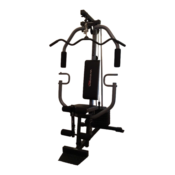
Model No. WESY1955.1
Serial No.
Write the serial number in the
space above for reference.
Serial Number Decal (under seat)
QUESTIONS?
As a manufacturer, we are com-
mitted to providing complete
customer satisfaction. If you have
questions, or if parts are missing,
DO NOT CONTACT THE STORE;
please contact Customer Care.
IMPORTANT: You must note the
product model number and
serial number (see the drawing
above) before contacting us:
1-877-992-5999
CALL TOLL-FREE:
Mon.–Fri. 6 a.m.–6 p.m. MT
Sat. 8 a.m.–4 p.m. MT
ON THE WEB:
www.weiderservice.com
CAUTION
Read all precautions and instruc-
tions in this manual before using
this equipment. Save this manual
for future reference.
All manuals and user guides at all-guides.com
USERʼS MANUAL
Advertisement
Table of Contents

Related Manuals for Weider 2250


Summary of Contents for Weider 2250
- Page 1 All manuals and user guides at all-guides.com www.weider.com USERʼS MANUAL Model No. WESY1955.1 Serial No. Write the serial number in the space above for reference. Serial Number Decal (under seat) QUESTIONS? As a manufacturer, we are com- mitted to providing complete customer satisfaction.
-
Page 2: Table Of Contents
All manuals and user guides at all-guides.com TABLE OF CONTENTS WARNING DECAL PLACEMENT ............. 2 IMPORTANT PRECAUTIONS . -
Page 3: Important Precautions
All manuals and user guides at all-guides.com IMPORTANT PRECAUTIONS WARNING: To reduce the risk of serious injury, read all important precautions and instructions in this manual and all warnings on your weight system before using your weight sys- tem. ICON assumes no responsibility for personal injury or property damage sustained by or through the use of this product. -
Page 4: Before You Begin
Thank you for selecting the versatile WEIDER PRO™ this manual. To help us assist you, note the product 2250 weight system. The weight system offers an model number and serial number before contacting us. impressive array of weight stations designed to devel- The model number and the location of the serial num- op every major muscle group of the body. -
Page 5: Part Identification Chart
All manuals and user guides at all-guides.com PART IDENTIFICATION CHART Refer to the drawings below to identify small parts used in assembly. The number in parentheses by each draw- ing is the key number of the part, from the PART LIST near the end of this manual. Note: Some small parts may have been preattached. - Page 6 All manuals and user guides at all-guides.com M4 Washer (82) M6 Nylon Locknut (2) M10 x 45mm Bolt (83) M6 Washer (10) M10 x 48mm Bolt (12) M8 Nylon Locknut (3) M6 x 50mm Screw (24) M8 Washer (8) M10 Nylon Locknut (21) M6 x 50mm Carriage Bolt (38) M6 x 16mm Screw (18) M8 x 57mm Bolt (80)
-
Page 7: Assembly
All manuals and user guides at all-guides.com ASSEMBLY • Tighten all parts as you assemble them, unless Make Assembly Easier instructed to do otherwise. Everything in this manual is designed to ensure • As you assemble the weight bench, make sure all that the weight bench can be assembled suc- parts are oriented as shown in the drawings. - Page 8 All manuals and user guides at all-guides.com 2. Slide the Front Upright (42) onto the M8 x 65mm Carriage Bolts (1) in the Base (4). Hand tighten two M8 Nylon Locknuts (3) onto the Carriage Bolts. Do not tighten the Nylon Locknuts yet. 3.
- Page 9 All manuals and user guides at all-guides.com 4. Attach the Top Frame (55) to the Front Upright (42) with two M8 x70mm Bolts (81), a Support Plate (84), and two M8 Nylon Locknuts (3). Attach the upper ends of the Weight Guides (62) to the Top Frame (55) with an M10 x 155mm Bolt (60), two M10 Washers (9), and an M10 Nylon Locknut (21).
- Page 10 All manuals and user guides at all-guides.com 7. Identify the Right Arm (48) and the Left Arm (47) by the position of the welded bracket on each Arm. Wet the end of the Left Arm (47) with soapy water, and slide a Large Pad (45) onto it. Make sure the Bracket Butterfly Arm Plastic Bushing (74) is in the Arm.
- Page 11 All manuals and user guides at all-guides.com 10. Route the Short Cable (58) around the 90mm Pulley (15). Tighten the M10 x 80mm Bolt (16), the M10 Washer (9), and the M10 Nylon Locknut (21). 11. Route the Short Cable (58) under a 90mm Pulley (15).
- Page 12 All manuals and user guides at all-guides.com 14. Wrap the Long Cable (23) over a “V”-pulley (6). Attach the “V”-pulley and a Long Cable Trap (50) to the Front Upright (42) with an M10 x 58mm Bolt (7) and an M10 Nylon Locknut (21). Make sure that the Long Cable Trap is positioned to hold the Cable in the groove of the “V”-pulley.
- Page 13 All manuals and user guides at all-guides.com 18. Route the Long Cable (23) over the 90mm Pulley (15). Tighten the M10 x 45mm Bolt (83) and the M10 Nylon Locknut (21). Bracket 19. Attach the Long Cable (23) to the Small “U”- bracket (67) with an M8 Nylon Locknut (3) and an M8 Washer (8).
- Page 14 All manuals and user guides at all-guides.com 21. Insert an M6 x 50mm Carriage Bolt (38) into the center hole in the Seat Plate (37). Attach the Seat Plate to the Seat (13) with two M6 x 16mm Screws (18). Insert the M6 x 50mm Carriage Bolt (38) into the indicated hole in the Seat Frame (36).
-
Page 15: Adjustment
All manuals and user guides at all-guides.com 25. Make sure that all parts have been properly tightened. The use of the remaining parts will be explained in ADJUSTMENT, beginning below. Before using the weight system, pull each cable a few times to make sure that the cables move smoothly over the pulleys. - Page 16 All manuals and user guides at all-guides.com ATTACHING AND REMOVING THE SEAT Set the Seat Frame (36) onto the indicated pin on the Front Upright (42). Attach the Seat Frame to the Front Upright with an M8 x 67mm Carriage Bolt (86) and the Seat Knob (40).
-
Page 17: Weight Resistance Chart
WEIGHT RESISTANCE CHART All manuals and user guides at all-guides.com This chart shows the approximate weight resistance at each station. The numbers refer to the 12.5 lb. weight plates. Weight resistance shown for the butterfly arm station is for each butterfly arm. Note: The actual resis- tance at each weight station may vary due to differences in individual weight plates, as well as friction between the cables, pulleys, and weight guides. -
Page 18: Troubleshooting
All manuals and user guides at all-guides.com TROUBLESHOOTING Inspect and tighten all parts each time the weight system is used. Replace any worn parts immediately. The weight system can be cleaned with a damp cloth and mild non-abrasive detergent; do not use solvents. TIGHTENING THE CABLES Woven cable, the type of cable used on the weight system, can stretch slightly when it is first used. -
Page 19: Cable Diagrams
CABLE DIAGRAMS All manuals and user guides at all-guides.com The cable diagrams show the proper routing of the Long Cable (23) and the Short Cable (58). Use the diagram to make sure that the two cables and the cable traps have been assembled correctly. If the cables have not been correctly routed, the weight system will not function properly and damage may occur. -
Page 20: Exercise Guidelines
All manuals and user guides at all-guides.com EXERCISE GUIDELINES THE FOUR BASIC TYPES OF WORKOUTS The combination of strength training and aerobic exer- cise will reshape and strengthen your body, plus Muscle Building develop your heart and lungs. To increase the size and strength of your muscles, PERSONALIZING YOUR EXERCISE PROGRAM push them close to their maximum capacity. - Page 21 All manuals and user guides at all-guides.com COOLING DOWN The repetitions in each set should be performed smoothly and without pausing. The exertion stroke of each repetition should last about half as long as the End each workout with 5 to 10 minutes of stretching. return stroke.
-
Page 22: Part List
PART LIST—Model No. WESY1955.1 All manuals and user guides at all-guides.com R0908A Key No. Qty. Description Key No. Qty. Description M8 x 65mm Carriage Bolt Right Press Arm M6 Nylon Locknut Left Arm M8 Nylon Locknut Right Arm Base 25mm Round Inner Cap Stabilizer Long Cable Trap “V”-pulley... -
Page 23: Exploded Drawing
EXPLODED DRAWING—Model No. WESY1955.1 All manuals and user guides at all-guides.com R0908A 10 43... -
Page 24: Ordering Replacement Parts
All manuals and user guides at all-guides.com ORDERING REPLACEMENT PARTS To order replacement parts, please see the front cover of this manual. To help us assist you, be prepared to provide the following information when contacting us: • the model number and serial number of the product (see the front cover of this manual) •...