
Related Manuals for Yamaha EF3000iS


Summary of Contents for Yamaha EF3000iS
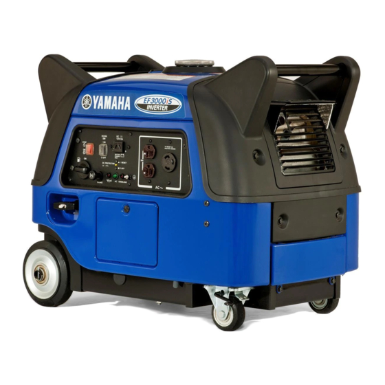
- Page 1 Generator OWNER’S MANUAL Read this manual carefully before operating this machine. EF3000iS EF3000iSE EF3000iSEB LIT-19626-02-21 7CH-28199-18...
- Page 2 Read this manual carefully before operating this machine. This manual should stay with this machine if it is sold.
- Page 3 INTRODUCTION Congratulations on your purchase of your new Yamaha. This manual will provide you with a good basic understanding of the operation and maintenance of this machine. If you have any questions regarding the operation or maintenance of your machine, please consult a Yamaha dealer.
- Page 4 OPERATING THE MACHINE. A WARNING indicates a hazardous sit- uation which, if not avoided, could result in death or serious injury. 9 Yamaha continually seeks advance- ments in product design and quality. NOTICE Therefore, while this manual contains the most current product information...
-
Page 5: Table Of Contents
DC protector ........10 Machine identification ....... 47 Fuel cock lever ........11 Caster lock lever ....... 11 WIRING DIAGRAM ......48 EF3000iS .......... 48 PREPARATION ........12 EF3000iSE ........49 Fuel ........... 12 EF3000iSEB ........50 Engine oil .......... 13 Ground (earth) terminal .... -
Page 6: Safety Information
SAFETY INFORMATION 9 This generator is not designed for on-board use. Do not use it while installed on the vehicle. 9 Do not modify the generator or use it with its parts removed. 9 Do not allow children to operate the generator. 9 Be sure to carry the generator only by its carrying handles. -
Page 7: Exhaust Fumes Are Poisonous
Exhaust fumes are poisonous 9 Using a generator indoors CAN KILL YOU IN MINUTES. Generator exhaust contains carbon monoxide. This is a poison you cannot see or smell. 9 NEVER use inside a home or garage, EVEN IF doors and windows are open. 741-092 9 Only use OUTSIDE and far away from windows, doors, and vents. -
Page 8: Electric Shock Prevention
9 Avoid placing any flammable materials near the exhaust outlet during operation. 741-097 9 In order to prevent overheating, ensure adequate airflow by keeping the machine at least 1 m (3 ft) from objects or other equipment. 741-118 9 Do not operate the engine with a dust cover or other objects covering it. -
Page 9: Connection Notes
Connection notes 9 Avoid connecting the generator to commercial power outlet. 9 Avoid connecting the generator in parallel with any other generator. 1 Correct 2 Incorrect Connection WARNING Before the generator can be connected to a build- ing’s electrical system, a licensed electrician must install an isolation (transfer) switch in the build- ing’s main fuse box. -
Page 10: Location Of Important Labels
LOCATION OF IMPORTANT LABELS Please read the following labels carefully before oper- ating this generator. Maintain or replace safety and instruction labels, as necessary. HOT EXHAUST 7WL-28176-10 DANGER Using a generator indoors CAN KILL YOU IN MINUTES. Generator exhaust contains carbon monoxide. This is a poison you cannot see or smell. - Page 11 Phase Single DC output 12V 12A Fuel Gasoline YAMAHA MOTOR POWERED PRODUCTS CO.,LTD. MADE IN JAPAN 7WL-24164-21 DISPLACEMENT : Read the owner’s manual and all labels before operating. Only operate in well-ventilated areas. Exhaust gas contains poisonous carbon monoxide. Check for spilled fuel or fuel leaks.
-
Page 12: Description
DESCRIPTION 1 Recoil starter 2 Fuel level gauge 3 Caster lock lever 4 Oil filler cap 5 Oil drain bolt 6 Battery box/Battery (For EF3000iSE, EF3000iSEB) 7 Muffler 8 Carrying handles (shaded) 793-107c 9 Fuel tank cap 793-108c – 7 –... -
Page 13: Control Panel
Control panel EF3000iS 1 Engine switch 2 Economy control switch 3 DC receptacle 4 AC receptacle 5 Ground (earth) terminal 6 Overload indicator light 7 AC pilot light 8 DC protector 9 Oil warning light 0 Choke knob q Fuel cock lever... -
Page 14: Engine Switch
The starter motor starts and the engine can be start- 763-119 Take your hand off the switch immediately after the engine starts. A EF3000iS B EF3000iSE, EF3000iSEB Oil warning light (red) When the oil level falls below the lower level, the oil warning light comes on and then the engine stops automatically. -
Page 15: Economy Control Switch
Reduce the load of the connected electric device below the specified rated output of the generator if the DC protector turns “ 3” (OFF). If the DC protector turns “ 3” (OFF) again, stop using the device immediately and consult a Yamaha dealer. – 10 –... -
Page 16: Fuel Cock Lever
Fuel cock lever The fuel cock supplies fuel from the fuel tank to the carburetor. The fuel cock has two positions. 1 ON With the lever in this position, fuel flows to the carbu- retor. Normal using is done with the lever in this position. 2 OFF With the lever in this position, fuel will not flow. -
Page 17: Preparation
PREPARATION Fuel WARNING 9 Fuel is highly flammable and poisonous. Check “SAFETY INFORMATION” (See page 2) carefully before filling. 9 Do not overfill the fuel tank, otherwise it may overflow when the fuel warms up and expands. 9 After fill the fuel, make sure the fuel tank cap is tightened securely. -
Page 18: Engine Oil
Full 5 “F” Empty 6 “E” Recommended fuel: Unleaded gasoline Fuel tank capacity: 7DF-020 Total: 13.0 L (3.43 US gal, 2.86 Imp gal) Engine oil NOTICE The generator has been shipped without engine oil. Do not start the engine until you have filled it with the sufficient engine oil. -
Page 19: Ground (Earth) Terminal
4. Fill the specified amount of the recommended engine oil, and then install and tighten the oil filler cap. NOTICE 9 Do not tilt the generator when adding engine 700-006 oil. This could result in overfilling and damage to the engine. 9 Be sure no foreign material enters the crank- case. -
Page 20: Battery
Battery (For EF3000iSE, EF3000iSEB) WARNING 9 Electrolyte is poisonous and dangerous since it contains sulfuric acid, which causes severe burns. Avoid any contact with skin, eyes or clothing and always shield your eyes when working near batteries. In case of contact, administer the following FIRST AID. - Page 21 5. Install the battery onto the battery box. 6. Connect the positive lead (red) to the positive (+) battery terminal, then the negative lead (black) to the negative (–) battery terminal. 7 Positive (+) lead (red) 8 Positive (+) battery terminal 762-045 9 Negative (–) lead (black) 0 Negative (–) battery terminal...
-
Page 22: Pre-Operation Check
9 Check oil level in engine. 9 If necessary, add recommended oil to specified level. 9 Check generator for oil leakage. The point where abnormality was recognized by 9 Check operation. 9 If necessary, consult a Yamaha dealer. – 17 –... -
Page 23: Operation
OPERATION WARNING 9 Never operate the engine in a closed area or it may cause unconsciousness and death within a short time. Operate the engine in a well ven- tilated area. 9 Before starting the engine, do not connect any electric devices. - Page 24 Electric Starting (For EF3000iSE, EF3000iSEB): 4. Turn the engine switch to the “6” (START). 4 “6” (START) NOTICE 763-120e If the engine fails to start, release the switch, wait a few seconds, then try again. Each attempt should be as short as possible to preserve the battery.
- Page 25 Manual Starting: 4. Turn the engine switch to “7” (ON). 4 “7” (ON) A EF3000iS B EF3000iSE, EF3000iSEB 763-120a 5. Pull the recoil starter slowly until it is engaged, then pull it briskly. 6. After the engine starts, warm up the engine until the engine does not stop when the choke knob is returned to the original position.
-
Page 26: Application Range
When using the generator, make sure the total load is within rated output of a genera- tor. Otherwise, generator damage may occur. 0.4–0.75 Power factor 0.8–0.95 (Efficiency 0.85) Rated voltage EF3000iS 12 V EF3000iSE –2,800 W –2,240 W –950 W Rated current... -
Page 27: High Altitude Operation
4000 ft. (1219 meters). If you operate your engine at altitudes above 4000 ft. (1219 meters) consistently, have your local Yamaha dealer perform the necessary carburetor modification. This engine should be operat- ed in its original configuration below 4000 ft. (1219 meters) as damage may occur if high altitude carbure- tor kit is installed and operated below 4000 ft. -
Page 28: Connection
Connection Alternating Current (AC) WARNING Be sure any electric devices are turned off before plugging them in. NOTICE 9 Be sure all electric devices including the lines and plug connections are in good condition before connection to the generator. 9 Be sure the total load is within generator rated output. - Page 29 Overload indicator light (red) The overload indicator light (red) comes on when an overload of a connected electrical device is detected, the inverter control unit overheats, or the AC output voltage rises. The electronic breaker will then activate, stopping power generation in order to protect the gen- erator and any connected electric devices.
- Page 30 Battery charging NOTICE 9 Do not connect a VRLA (Valve Regulated Lead Acid) battery. To charge a VRLA battery, a spe- cial (constant voltage) battery charger is required. 9 Do not use AC and DC power at the same time or the generator may be damaged.
- Page 31 I” (RESET). If the DC protector turns off again, stop charging the battery immediately and consult a Yamaha dealer. 9 Follow instructions in the owner’s manual for the battery to determine the end of battery charging. 9 Measure the specific gravity of electrolyte to determine if the battery is fully charged.
- Page 32 WARNING 9 Electrolyte is poisonous and dangerous since it contains sulfuric acid, which causes severe burns. Avoid any contact with skin, eyes or clothing and always shield your eyes when working near batteries. In case of contact, administer the following FIRST AID. 9 EXTERNAL: Flush with plenty of water.
-
Page 33: Stopping The Engine
1 “3” (OFF) 763-126b 3. Disconnect any electric devices. 761-080 4. Turn the engine switch to “5” (STOP). 2 “5” (STOP) A EF3000iS B EF3000iSE, EF3000iSEB 763-120b 5. Turn the fuel cock lever to OFF. 3 OFF 705-073a – 28 –... -
Page 34: Periodic Maintenance
WARNING If you are not familiar with maintenance work, have a Yamaha dealer do it for you. Maintenance chart WARNING Stop the engine before starting maintenance work. - Page 35 *2 ..The air filter element needs to be cleaned more frequently when using in unusually wet or dusty areas. ★ ..Since these items require special tools, data and technical skills, have a Yamaha dealer per- form the service.
-
Page 36: Spark Plug Inspection
Spark plug inspection The spark plug is an important engine component, which should be checked periodically. 1. Remove the screw and the cover. 1 Screw 788-003a 2 Cover 2. Remove the spark plug cap and the spark plug. 3 Spark plug cap 3. -
Page 37: Carburetor Adjustment
Carburetor adjustment The carburetor is a vital part of the engine. Adjusting should be left to a Yamaha dealer with the professional knowledge, specialized data, and equipment to do so properly. Engine oil replacement WARNING Avoid draining the engine oil immediately after stopping the engine. - Page 38 6. Install a new gasket and the oil drain bolt, and then tighten the bolt. Oil drain bolt tightening torque: 17 Nm (1.7 m·kgf, 12 ft·lbf) 7. Add engine oil to the correct level. 9 Correct level NOTICE Be sure no foreign material enters the crankcase. 700-006a Recommended engine oil: å...
-
Page 39: Muffler Screen And Spark Arrester
Muffler screen and spark arrester WARNING The engine and the muffler will be very hot after the engine has been run. Avoid touching the engine and the muffler while they are still hot with any part of your body or 741-105 clothing during inspection or repair. -
Page 40: Air Filter
5. Remove the carbon deposits on the muffler screen and the spark arrester using a wire brush. NOTICE When cleaning, use the wire brush lightly to avoid damaging or scratching of the muffler screen and 711-075 spark arrester. 6. Check the muffler screen and the spark arrester. Replace them if damaged. - Page 41 2. Remove the clips holding the air filter case cover. 3. Remove the air filter case cover and the air filter element. 3 Clip 4 Air filter case cover 788-013 4. Remove the foam element from the air filter ele- ment frame.
-
Page 42: Fuel Tank Filter
Be sure the air filter element sealing surface matches the air filter case so there is no air leak. 9. Install the air filter case cover in its original posi- tion and install the clips. 10. Install the cover and tighten the bolts. Cover bolt tightening torque: 7 Nm (0.7 m·kgf, 5.1 ft·lbf) Fuel tank filter... -
Page 43: Battery
Regulated Lead Acid) battery. There is no need to check the electrolyte or to add distilled water. To charge the battery Have a Yamaha dealer charge the battery as soon as possible if it seems to have discharged. NOTICE To charge a VRLA battery, a special (constant-volt- age) battery charger is required. -
Page 44: Fuse Replacement
2 Battery box 2. Replace the blown fuse with one of proper amper- age. Specified fuse: 10 A If the fuse immediately blows again, consult a Yamaha 779-070a dealer. 3. Install the battery box and the cover. Battery box bolt tightening torque: 7 Nm (0.7 m·kgf, 5.1 ft·lbf) -
Page 45: Troubleshooting
Poor spark 2 Spark plug dirty with carbon or wet ..Remove carbon or wipe spark plug dry. 2 Faulty ignition system ..Consult a Yamaha deal- 791-001d Generator won’t produce power 2 Safety device (AC) to OFF ..Stop the engine, then restart. - Page 46 Replace or Clean the spark hand while testing. adjust gap. plug. Does not spark Clean Check the following. Clogged replace. S Engine does not start. 9 Fuel line clogging 9 Air filter element clogging Consult a Yamaha dealer. – 41 –...
-
Page 47: Storage
Drain the fuel 1. Turn the engine switch to “5” (STOP). 1 “5” (STOP) A EF3000iS B EF3000iSE, EF3000iSEB 2. Remove the fuel tank cap and the fuel tank filter. Extract the fuel from the fuel tank into an approved gasoline container using a commercially available hand siphon. -
Page 48: Engine
6. Drain the fuel remaining in the carburetor into an approved container by loosening the drain screw on the carburetor float chamber. 5 Drain screw 7. Tighten the drain screw. 707-102c 8. Turn the engine switch to “5” (STOP). 9. Turn the fuel cock lever to OFF. 10. -
Page 49: Battery
Battery (For EF3000iSE, EF3000iSEB) 1. Remove the battery. 2. Store the battery in a cool, dark and dry place and charge it once a month. Do not store the battery in an excessive cold or warm place [i.e., less than 0 °C (30 °F) or more than 30 °C 762-003 (90 °F)]. -
Page 50: Exhaust Emission Control System And Components
ROAD ENGINES. The acronyms conform to the latest version of the SAE’s recommended practice docu- ment J1930, “Diagnostic Acronyms, Terms, and Definitions For Electrical/Electronic System”. It is recommended that these items be serviced by a Yamaha dealer. – 45 –... -
Page 51: Specifications
SPECIFICATIONS Dimensions Unit EF3000iS EF3000iSE EF3000iSEB Overall length mm (in) 680 (26.8) Overall width mm (in) 445 (17.5) Overall height mm (in) 555 (21.9) Dry weight kg (lb) 62 (136.6) 69 (152.1) 71 (156.5) Engine Unit EF3000iS EF3000iSE EF3000iSEB Type... -
Page 52: Consumer Information
Identification number records PRI-I.D. NUMBER Record your Primary I.D., and serial num- bers in the spaces provided, to assist you MODEL in ordering spare parts from a Yamaha dealer. PRI-I.D. Also record and keep these I.D. numbers SERIAL No. in a separate place in case your machine CODE is stolen. -
Page 53: Wiring Diagram
WIRING DIAGRAM EF3000iS 770-052 Color code 1 Main coil Black 2 Sub coil Brown 3 DC coil Green 4 DC rectifier Blue 5 Control unit Orange 6 AC pilot light 7 AC receptacle White 8 Ground (earth) terminal Yellow 9 Economy control switch... -
Page 54: Ef3000Ise
EF3000iSE START G/Y R/W 770-052 Color code 1 Main coil p Rectifier Black 2 Sub coil a TCI magneto Brown 3 DC coil s TCI unit Green 4 DC rectifier d Spark plug Blue 5 Control unit f Stepping motor Orange 6 AC pilot light 7 AC receptacle... -
Page 55: Ef3000Iseb
EF3000iSEB START G/Y R/W 770-052a Color code 1 Main coil p Rectifier Black 2 Sub coil a TCI magneto Brown 3 DC coil s TCI unit Green 4 DC rectifier d Spark plug Blue 5 Control unit f DC-DC converter Orange 6 AC pilot light g Stepping motor... -
Page 56: Yamaha Extended Service (Y.e.s.)
9 Y.E.S. is flexible. You can choose the plan that’s right for you: 12 months, 24 months or 36 months coverage. 9 Y.E.S. is administered by the same Yamaha people that handle your warranty - and it shows in the comprehensive coverage benefits. There are no hour limitations and Y.E.S. covers manufacturing defects just like your warranty. - Page 58 PRINTED IN JAPAN 2015.03-0.5×1 ! PRINTED ON RECYCLED PAPER...