
Related Manuals for Yamaha EF3000iS


Summary of Contents for Yamaha EF3000iS
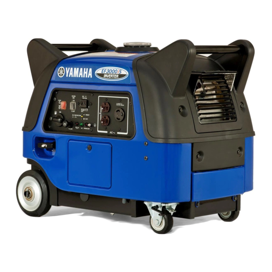
- Page 1 Generator OWNER’S MANUAL Read this manual carefully before operating this machine. EF3000iS EF3000iSE EF3000iSEB LIT-19626-01-71 7CH-28199-15...
- Page 2 Read this manual carefully before operating this machine. This manual should stay with this machine if it is sold.
- Page 3 INTRODUCTION Congratulations on your purchase of your new Yamaha. This manual will provide you with a good basic understanding of the operation and main- tenance of this machine. If you have any questions regarding the operation or maintenance of your machine, please consult a Yamaha dealer.
- Page 4 OPERATING THE MACHINE. A WARNING indicates a hazardous situ- ation which, if not avoided, could result in death or serious injury. 9 Yamaha continually seeks advance- ments in product design and quality. NOTICE Therefore, while this manual contains the most current product information...
-
Page 5: Table Of Contents
CASTER LOCK LEVER.....11 DIMENSIONS ........43 PRE-OPERATION CHECK....12 ENGINE ..........43 FUEL..........12 GENERATOR........43 ENGINE OIL ........13 WIRING DIAGRAM .......44 GROUND (earth) TERMINAL ....13 EF3000iS ...........44 BATTERY ...........14 EF3000iSE.........45 OPERATION .........16 EF3000iSEB ........46 STARTING THE ENGINE ....16 APPLICATION RANGE......19 CONNECTION........20 STOPPING THE ENGINE....25... - Page 6 YAMAHA MOTOR CORPORATION, U.S.A. EF SERIES GENERATORS 3-YEAR LIMITED WARRANTY ....47 WARRANTY QUESTIONS AND ANSWERS ..........49 YAMAHA OUTDOOR POWER EQUIPMENT CALIFORNIA EVAPORATIVE EMISSION CONTROL WARRANTY STATEMENT ....50 YAMAHA MOTOR CORPORATION, U.S.A. SMALL OFF ROAD ENGINES CALIFORNIA EMISSION CONTROL WARRANTY .......51 YAMAHA EXTENDED SERVICE (Y.E.S.) ..........55...
-
Page 7: Location Of Important Labels
LOCATION OF IMPORTANT LABELS Please read the following labels carefully before oper- ating this generator. Maintain or replace safety and instruction labels, as necessary. HOT EXHAUST 7WL-28176-10 DANGER Using a generator indoors CAN KILL YOU IN MINUTES. Generator exhaust contains carbon monoxide. This is a poison you cannot see or smell. - Page 8 120V Phase Single DC output 12V 12A Fuel Gasoline YAMAHA MOTOR POWERED PRODUCTS CO.,LTD. MADE IN JAPAN 7WL-24164-21 WARNING Electrocution or property damage can occur: Do not connect this generator to any building ’s electrical system unless an isolation switch has been installed by a licensed elec- trician.
-
Page 9: Safety Information
SAFETY INFORMATION 9 This generator is not designed for on-board use. Do not use it while installed on the vehicle. 9 Do not modify the generator or use it with its parts removed. 9 Do not allow children to operate the generator. 9 Be sure to carry the generator only by its carrying handle(s). -
Page 10: Fuel Is Highly Flammable And Poisonous
FUEL IS HIGHLY FLAMMABLE AND POISONOUS 9 Always turn off the engine when refuelling. 9 Never refuel while smoking or in the vicinity of an open flame. 9 Take care not to spill any fuel on the engine or muf- 741-093 fler when refuelling. -
Page 11: Electric Shock Prevention
9 Do not operate the engine with a dust cover or other objects covering it. 9 When covering the generator, be sure to do so only after the engine and muffler have completely 741-099 cooled down. ELECTRIC SHOCK PREVENTION 9 Never operate the engine in rain or snow. 741-101 9 Never touch the generator with wet hands or elec- trical shock will occur. -
Page 12: Connection Notes
CONNECTION NOTES 9 Avoid connecting the generator to commercial power outlet. 9 Avoid connecting the generator in parallel with any other generator. 1 Correct 2 Incorrect CONNECTION WARNING Before the generator can be connected to a build- ing’s electrical system, a licensed electrician must install an isolation (transfer) switch in the build- ing’s main fuse box. -
Page 13: Description
DESCRIPTION 1 Recoil starter 2 Oil filler cap 3 Oil drain bolt 4 Battery box/Battery (For EF3000iSE, EF3000iSEB) 5 Muffler 6 Carrying handles (shaded) 7 Fuel tank cap 793-107c 793-108c – 7 –... -
Page 14: Control Panel
EF3000iS CONTROL PANEL 1 Engine switch 2 Economy control switch 3 DC receptacle 4 AC receptacle 5 Ground (earth) terminal 6 Overload indicator light 7 AC pilot light 8 DC protector 9 Oil warning light 0 Choke knob q Fuel cock knob... -
Page 15: Engine Switch
The starter motor starts and the engine can be started. 763-119 Take your hand off the switch immediately after the engine starts. A EF3000iS B EF3000iSE, EF3000iSEB OIL WARNING LIGHT (red) When the oil level falls below the lower level, the oil warning light comes on and then the engine stops auto- matically. -
Page 16: Economy Control Switch
Reduce the load of the connected electric device below the specified rated output of the generator if the DC protector turns “OFF”. If the DC protector turns “OFF” again, stop using the device immedi- ately and consult a Yamaha dealer. – 10 –... -
Page 17: Fuel Cock Knob
FUEL COCK KNOB The fuel cock supplies fuel from the fuel tank to the car- buretor. The fuel cock has two positions. 1 “ON” With the knob in this position, fuel flows to the carbure- tor. Normal using is done with the knob in this position. 2 “OFF”... -
Page 18: Pre-Operation Check
Fuel tank capacity: Total: 13.0 L (3.43 US gal, 2.86 Imp gal) 707-033a Your Yamaha engine has been designed to use regular unleaded gasoline with a pump octane number ((R + M)/2) of 86 or higher, or research octane number of 91 or higher. -
Page 19: Engine Oil
NOTICE 9 Immediately wipe off spilled fuel with a clean, dry, soft cloth, since fuel may deteriorate paint- ed surfaces or plastic parts. 9 Use only unleaded gasoline. The use of leaded gasoline will cause severe damage to internal engine parts. ENGINE OIL NOTICE The generator has been shipped without engine oil. -
Page 20: Battery
BATTERY (For EF3000iSE, EF3000iSEB) WARNING 9 Electrolyte is poisonous and dangerous since it contains sulfuric acid, which causes severe burns. Avoid any contact with skin, eyes or clothing and always shield your eyes when working near batteries. In case of contact, administer the following FIRST AID. - Page 21 5. Install the battery onto the battery box. 6. Connect the positive lead (red) to the positive bat- tery (+) terminal, then the negative lead (black) to the negative (–) battery terminal. 1 Positive (+) lead (red) 2 Positive (+) battery terminal 762-045 3 Negative (–) lead (black) 4 Negative (–) battery terminal...
-
Page 22: Operation
OPERATION WARNING 9 Never operate the engine in a closed area or it may cause unconsciousness and death within a short time. Operate the engine in a well venti- lated area. 9 Before starting the engine, do not connect any electric devices. - Page 23 Electric Starting (For EF3000iSE, EF3000iSEB): 4. Turn the engine switch to “START”. 1 6 “START” 763-120e NOTICE If the engine fails to start, release the switch, wait a few seconds, then try again. Each attempt should be as short as possible to preserve the battery. Do not crank the engine more than 5 seconds on any one attempt.
- Page 24 Manual Starting: 4. Turn the engine switch to “ON”. 1 7 “ON” A EF3000iS B EF3000iSE, EF3000iSEB 763-120a 5. Pull slowly on the recoil starter until it is engaged, then pull it briskly. 6. After the engine starts, warm up the engine until the engine does not stop when the choke knob is returned to the original position.
-
Page 25: Application Range
When using the generator, make sure the total load is within rated output of a generator. Otherwise, generator damage may occur. 0.4–0.75 Power factor 0.8–0.95 (Efficiency 0.85) Rated voltage EF3000iS 12 V EF3000iSE –2,800 W –2,240 W –950 W Rated current... -
Page 26: Connection
CONNECTION Alternating Current (AC) WARNING Be sure any electric devices are turned off before plugging them in. NOTICE 9 Be sure all electric devices including the lines and plug connections are in good condition before connection to the generator. 9 Be sure the total load is within generator rated output. - Page 27 Overload indicator light (red) The overload indicator light (red) comes on when an overload of a connected electrical device is detected, the inverter control unit overheats, or the AC output voltage rises. The electronic breaker will then activate, stopping power generation in order to protect the gen- erator and any connected electric devices.
- Page 28 Battery charging NOTICE Do not connect a VRLA (Valve Regulated Lead Acid) battery. To charge a VRLA battery, a special (constant-voltage) battery charger is required. 9 The generator DC rated voltage is 12 V. 9 Start the engine first, and then connect the gener- ator to the battery for charging.
- Page 29 To restart charging the battery, turn the DC pro- tector on by pressing its button to “RESET”. If the DC protector turns off again, stop charging the battery immediately and consult a Yamaha dealer. 9 Follow instructions in the owner’s manual for the battery to determine the end of battery charging.
- Page 30 WARNING 9 Electrolyte is poisonous and dangerous since it contains sulfuric acid, which causes severe burns. Avoid any contact with skin, eyes or clothing and always shield your eyes when working near batteries. In case of contact, administer the following FIRST AID. 9 EXTERNAL: Flush with plenty of water.
-
Page 31: Stopping The Engine
1 3 “OFF” 763-126b 2. Disconnect any electric devices. 761-080 3. Turn the engine switch to “STOP”. 1 5 “STOP” A EF3000iS B EF3000iSE, EF3000iSEB 763-120b 4. Turn the fuel cock knob to “OFF”. 1 “OFF” 705-073a – 25 –... -
Page 32: Periodic Maintenance
WARNING If you are not familiar with maintenance work, have a Yamaha dealer do it for you. MAINTENANCE CHART WARNING Stop the engine before starting maintenance work. - Page 33 *1·····Initial replacement of the engine oil is after one month or 20 hours of operation. *2·····The air filter element needs to be cleaned more frequently when using in unusually wet or dusty areas. ★····· Since these items require special tools, data and technical skills, have a Yamaha dealer perform the service. – 27 –...
-
Page 34: Spark Plug Inspection
SPARK PLUG INSPECTION The spark plug is an important engine component, which should be checked periodically. 1. Remove the screw and the cover. 1 Screw 788-003a 2 Cover 2. Remove the spark plug cap and the spark plug. 3. Check for discoloration and remove the carbon. The porcelain insulator around the center elec- trode of spark plug should be a medium-to-light tan 760-028... -
Page 35: Carburetor Adjustment
CARBURETOR ADJUSTMENT The carburetor is a vital part of the engine. Adjusting should be left to a Yamaha dealer with the professional knowledge, specialized data, and equipment to do so properly. ENGINE OIL REPLACEMENT WARNING Avoid draining the engine oil immediately after stopping the engine. - Page 36 6. Install a new gasket and the oil drain bolt, and then tighten the bolt. Oil drain bolt tightening torque: 17 Nm (1.7 m·kgf, 12 ft·lbf) 7. Add engine oil to the upper level. 1 Upper level NOTICE Be sure no foreign material enters the crankcase. 700-006a Recommended engine oil: å...
-
Page 37: Muffler Screen And Spark Arrester
MUFFLER SCREEN AND SPARK ARRESTER WARNING The engine and the muffler will be very hot after the engine has been run. Avoid touching the engine and the muffler while 741-105 they are still hot with any part of your body or cloth- ing during inspection or repair. -
Page 38: Air Filter
5. Remove the carbon deposits on the muffler screen and the spark arrester using a wire brush. NOTICE When cleaning, use the wire brush lightly to avoid damaging or scratching of the muffler screen and 711-075 spark arrester. 6. Check the muffler screen and the spark arrester. Replace them if damaged. - Page 39 4. Remove the foam element from the air filter ele- ment frame. 5 Foam element 6 Air filter element frame 710-061a 5. Wash the foam element in solvent and dry it. WARNING Never use solvent while smoking or in the vicinity of an open flame.
-
Page 40: Fuel Tank Filter
9. Install the air filter cover in its original position and install the clips. 10. Install the cover and tighten the bolts. Cover bolt tightening torque: 7 Nm (0.7 m·kgf, 5.1 ft·lbf) FUEL TANK FILTER WARNING Never use the gasoline while smoking or in the vicinity of open flame. -
Page 41: Battery
Regulated Lead Acid) battery. There is no need to check the electrolyte or to add distilled water. To charge the battery Have a Yamaha dealer charge the battery as soon as possible if it seems to have discharged. NOTICE To charge a VRLA battery, a special (constant-volt- age) battery charger is required. -
Page 42: Fuse Replacement
2 Battery box 2. Replace the blown fuse with one of proper amper- age. Specified fuse: 10 A If the fuse immediately blows again, consult a Yamaha 779-070a dealer. 3. Install the battery box and the cover. Battery box bolt tightening torque: 7 Nm (0.7 m·kgf, 5.1 ft·lbf) -
Page 43: Troubleshooting
Poor spark 2 Spark plug dirty with carbon or wet ..Remove car- bon or wipe spark plug dry. 2 Faulty ignition system ..Consult a Yamaha dealer. 791-001d Generator won’t produce power 2 Safety device (AC) to “OFF” ..Stop the engine, then restart. - Page 44 Clean the spark hand while testing. adjust gap. plug. Does not spark Clean Check the following Clogged replace S Engine does not start. 9 Fuel line clogging 9 Air filter element clog- ging. Consult a Yamaha dealer. – 38 –...
-
Page 45: Storage
DRAIN THE FUEL 1. Turn the engine switch to “STOP”. 1 5 “STOP” A EF3000iS B EF3000iSE, EF3000iSEB 2. Remove the fuel tank cap and the fuel tank filter. Extract the fuel from the fuel tank into an approved gasoline container using a commercially available hand siphon. -
Page 46: Engine
6. Drain the fuel remaining in the carburetor into an approved container by loosening the drain screw on the carburetor float chamber. 1 Drain screw 7. Tighten the drain screw. 707-102c 8. Turn the engine switch to “STOP”. 9. Turn the fuel cock knob to “OFF”. 10. -
Page 47: Battery
BATTERY (For EF3000iSE, EF3000iSEB) 1. Remove the battery. 2. Store the battery in a cool, dark and dry place and charge it once a month. Do not store the battery in an excessive cold or warm place [i.e., less than 0 °C (30 °F) or more than 30 °C 762-003 (90 °F)]. -
Page 48: Exhaust Emission Control
ROAD ENGINES. The acronyms conform to the latest version of the SAE’s recommended practice docu- ment J1930, “Diagnostic Acronyms, Terms, and Definitions For Electrical/Electronic System”. It is recommended that these items be serviced by a Yamaha dealer. – 42 –... -
Page 49: Specifications
SPECIFICATIONS DIMENSIONS Unit EF3000iS EF3000iSE EF3000iSEB Overall length mm (in) 680 (26.8) Overall width mm (in) 445 (17.5) Overall height mm (in) 555 (21.9) Dry weight kg (lb) 62 (136.6) 69 (152.1) 71 (156.5) ENGINE EF3000iS EF3000iSE EF3000iSEB Unit Type... -
Page 50: Wiring Diagram
WIRING DIAGRAM EF3000iS 770-052 1 Main coil Color code 2 Sub coil Black 3 DC coil Brown 4 DC rectifier Green 5 Control unit Blue 6 AC pilot light Orange 7 AC receptacle 8 Ground (earth) terminal White 9 Economy control switch... -
Page 51: Ef3000Ise
EF3000iSE START G/Y R/W 770-052 1 Main coil p Rectifier Color code 2 Sub coil a T.C.I. magneto Black 3 DC coil s T.C.I. unit Brown 4 DC rectifier d Spark plug Green 5 Control unit f Stepping motor Blue 6 AC pilot light Orange 7 AC receptacle... -
Page 52: Ef3000Iseb
EF3000iSEB START G/Y R/W 770-052a 1 Main coil p Rectifier Color code 2 Sub coil a T.C.I. magneto Black 3 DC coil s T.C.I. unit Brown 4 DC rectifier d Spark plug Green 5 Control unit f DC-DC converter Blue 6 AC pilot light g Stepping motor Orange... -
Page 53: Yamaha Motor Corporation
Yamaha generator service dealer will, All 1995 and Later EF Models free of charge, repair or replace, at Yamaha’s Three (3) years from the original purchase date option, any part judged defective by Yamaha due to faulty workmanship or material from the factory. - Page 54 TIAL DAMAGES, SO THE ABOVE EXCLUSION MAY NOT APPLY TO YOU. THIS WARRANTY GIVES YOU SPECIFIC LEGAL RIGHTS, AND YOU MAY ALSO HAVE OTHER RIGHTS WHICH VARY FROM STATE TO STATE. YAMAHA MOTOR CORPORATION, U.S.A. Post Office Box 6555 Cypress, California 90630 – 48 –...
-
Page 55: Warranty Questions And Answers
Yamaha Motor exactly as specified in the Owner’s Manual? Corporation, U.S.A. by the selling dealer at the A. No. The warranty on a new Yamaha cannot time of your purchase. If you should move after be “voided” or “cancelled.”... -
Page 56: Yamaha Outdoor Power
If any evaporative emis- coverage, you should contact Yamaha Customer sion-related part on your equipment is defective, Relations at 1-800-962-7926. the part will be repaired or replaced by Yamaha. YAMAHA MOTOR CORPORATION, USA Post Office Box 6555 Cypress, California 90630... -
Page 57: Yamaha Motor Corporation
Yamaha recommends that you retain all receipts covering maintenance on your SORE engine, but Yamaha cannot deny warranty solely for the lack of receipts or for your failure to ensure the performance of all scheduled maintenance. - Page 58 instructions required by subsection (d) must be warranted for the warranty period defined in Subsection (b)(2). If any such part fails during the period of warranty coverage, it must be repaired or replaced by the manufacturer according to Subsection (4) below. Any such part repaired or replaced under the warranty must be warranted for the remaining warranty period.
- Page 59 This work must be done at an authorized Yamaha dealer. Give notice to an authorized Yamaha dealer of any apparent defects(s) within a reasonable period of time after discovery. The SORE engine must be made available for inspection by an authorized Yamaha dealer.
- Page 60 This warranty does not cover damage resulting from accidents, acts of nature, or other events or occur- rences beyond the control of Yamaha. Yamaha Motor Corporation, U.S.A. expressly disclaims responsi- bility for any and all consequential damages, such as loss of time, inconvenience, loss or use of the SORE engine, or commercial loss.
-
Page 61: Yamaha Extended Service (Y.e.s.)
9 Y.E.S. is flexible. You can choose the plan that’s right for you: 12 months, 24 months or 36 months coverage. 9 Y.E.S. is administered by the same Yamaha people that handle your warranty - and it shows in the comprehensive coverage benefits. There are no hour limitations and Y.E.S. covers manufacturing defects just like your warranty. - Page 62 — MEMO —...
- Page 64 PRINTED IN JAPAN 2011.11-2.0×1 ! PRINTED ON RECYCLED PAPER...