Table of Contents
Advertisement
Quick Links
USER'S MANUAL
Of
AMD 780V & AMD SB700
Based
M/B For Socket AM2+ 64-bit Quad Core
AMD Processor
NO. G03-XBLUE78VA2 -F
:
Rev
1.0
Release date: Aug, 2008
Trademark:
* Specifications and information contained in this documentation are furnished for information use only, and are
subject to change at any time without notice, and should not be construed as a commitment by manufacturer.
Advertisement
Table of Contents

Related Manuals for JETWAY XBLUE-78VA2


Summary of Contents for JETWAY XBLUE-78VA2
- Page 1 USER'S MANUAL AMD 780V & AMD SB700 Based M/B For Socket AM2+ 64-bit Quad Core AMD Processor NO. G03-XBLUE78VA2 -F : Release date: Aug, 2008 Trademark: * Specifications and information contained in this documentation are furnished for information use only, and are subject to change at any time without notice, and should not be construed as a commitment by manufacturer.
- Page 2 Environmental Protection Announcement Do not dispose this electronic device into the trash while discarding. To minimize pollution and ensure environment protection of mother earth, please recycle.
-
Page 3: Table Of Contents
TABLE OF CONTENT USER’S NOTICE........................iii MANUAL REVISION INFORMATION ................iii COOLING SOLUTIONS ......................iii CHAPTER 1 INTRODUCTION OF AMD 790X CROSSFIREX MOTHERBOARDS FEATURES OF MOTHERBOARD ..................1 1-1.1 SPECIAL FEATURES OF MOTHERBOARD............ 2 SPECIFICATION........................4 PERFORMANCE LIST......................5 LAYOUT DIAGRAM & JUMPER SETTING ..............6 CHAPTER 2 HARDWARE INSTALLATION HARDWARE INSTALLATION STEPS................ -
Page 4: User's Notice
USER’S NOTICE COPYRIGHT OF THIS MANUAL BELONGS TO THE MANUFACTURER. NO PART OF THIS MANUAL, INCLUDING THE PRODUCTS AND SOFTWARE DESCRIBED IN IT MAY BE REPRODUCED, TRANSMITTED OR TRANSLATED INTO ANY LANGUAGE IN ANY FORM OR BY ANY MEANS WITHOUT WRITTEN PERMISSION OF THE MANUFACTURER. THIS MANUAL CONTAINS ALL INFORMATION REQUIRED TO USE NF6100-400 / 405 PPC MOTHERBOARD AND WE DO ASSURE THIS MANUAL MEETS USER’S REQUIREMENT BUT WILL CHANGE, CORRECT ANY TIME WITHOUT NOTICE. -
Page 5: Features Of Motherboard
Chapter 1 Introduction of AMD 780V Motherboards Features of motherboard The AMD 780V chipset motherboard series are based on the latest AMD 780V Chipset and the SB700 chipset which supports the innovative 64-bit dual core and quad core multi-tasking Socket AM2+ AMD Phenom™ processors. With an integrated low-latency high-bandwidth DDRII memory controller and a highly-scalable Hyper Transport technology-based system bus up to HT3.0. -
Page 6: 1-1.1 Special Features Of Motherboard
demands which are also equipped with hardware monitor function on system to monitor and protect your system and maintain your non-stop business computing. Some special features--- CPU Thermal Throttling/ CPU Vcore X-shift / CPU Smart Fan / DeBug in this motherboard are designed Port/ OC-CON /Power On Button/Reset Button/G.P.I Function for power user to use the over-clocking function in more flexible ways. - Page 7 OC-CON ---(High-polymer Solid Electrolysis Aluminum Capacitors) The working temperature is from 55 degrees Centigrade below zero to 125 degrees Centigrade, OC-CON capacitors possess superior physical characteristics that can be while reducing the working temperature between 20 degrees Centigrade each time, intact extension 10 times of effective product operation lives, at not rising degrees Centigrade of working temperatures each time a relative one, life of product decline 10% only too.
-
Page 8: Specification
Specification Spec Description ∗ ATX form factor 4 layers PCB size: 29.5cm x20cm Design * AMD 780V North Bridge Chipset Chipset * AMD SB700 South Bridge Chipset ∗ Support 64bit AMD Socket AM2+ processor utilizing Flip-Chip Pin Grid Array package ∗... -
Page 9: Performance List
Performance List The following performance data list is the testing result of some popular benchmark testing programs. These data are just referred by users, and there is no responsibility for different testing data values gotten by users (the different Hardware & Software configuration will result in different benchmark testing results.) Performance Test Report AMD Athlon 5000+... -
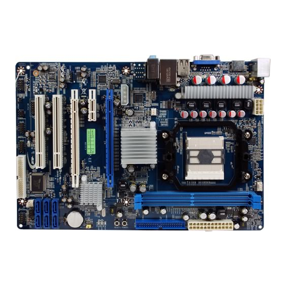
Page 10: Layout Diagram & Jumper Setting
Layout Diagram Line-IN RJ45 LAN Line-OUT Connector PS/2 Mouse HDMI Connector PS/2 Keyboard MIC-IN ATX 12V Power Connector CPU Socket AM2+ KBMB/USB Power on (JP1) PS2 KB/Mouse Port CPUFAN (KB) HDMI Connector DDR2 Socket x 2 ATX Power Conn. VGA Connector USB Port (CN1) RJ45 Over... - Page 11 Jumpers Jumper Name Description Page Keyboard/USB Power On Enabled/Disabled 3-pin Block JBAT CMOS RAM Clear 3-pin Block Connectors Connector Name Description Page ATXPWR1 ATX Power Connector 24-pin Block P.14 ATX12V1 ATX 12V Power Connector 8-pin Block P.14 PS/2 Mouse & PS/2 Keyboard Connector 6-pin Female P.14 USB from CN1...
-
Page 12: Chapter 2 Hardware Installation
Chapter 2 Hardware Installation Turn off your power when adding or removing expansion cards or other WARNING! system components. Failure to do so may cause severe damage to both your motherboard and expansion cards. Hardware installation Steps Before using your computer, you had better complete the following steps: 1. -
Page 13: Install Cpu
Connect ATX power cable back to ATX power connector Note: When should clear CMOS 1. Troubleshooting 2. Forget password 3. After over clocking system boot fail JBAT JBAT 1-2 Closed Normal 2-3 Closed Clear CMOS CMOS RAM Clear Setting Install CPU 2-3-1 Glossary Chipset (or core logic) - two or more integrated circuits which control the interfaces between the system processor, RAM, I/O devises, and adapter cards. -
Page 14: About Amd Athlon64 Socket Am2+ Cpu
Front Side Bus Frequency - the working frequency of the motherboard, which is generated by the clock generator for CPU, DRAM and PCI BUS. CPU L2 Cache - the flash memory inside the CPU, normal it depend on CPU type. 2-3-2 About AMD Athlon64 Socket AM2+ CPU This motherboard provides a surface mount, Zero Insertion Force (ZIF) socket, referred to as the mPGA940 socket supports AMD Athlon64 processor in the package utilizes Flip-Chip Pin... -
Page 15: Expansion Cards
*DDR2 1066 could only be reached in the case of overclocking. Recommend DIMM Module Combination One DIMM Module ----Plug in DIMM1 Two DIMM Modules---Plug in DIMM1 and DIMM2 or DIMM3 and DIMM4 for Dual channel function Dual channel Limited! 1. Dual channel function only supports when 2 DIMM Modules plug in either both DIMM1 & DIMM2or DIMM3 &DIMM4, or four DIMM Modules plug in DIMM1~DIMM4. -
Page 16: Interrupt Request Table For This Motherboard
Standard Interrupt Assignments Priority Standard function System Timer Keyboard Controller Programmable Interrupt Communications Port (COM2) Communications Port (COM1) Sound Card (sometimes LPT2) Floppy Disk Controller Printer Port (LPT1) System CMOS/Real Time Clock ACPI Mode when enabled 10 * IRQ Holder for PCI Steering 11 * IRQ Holder for PCI Steering 12 *... -
Page 17: Connectors, Headers
PCI-E 2.0x16 Slot@16-lane PCI-E2.0 x1 Slot 32-bit PCI Slot PCI-E 2.0x16 Slot@4-lane 2-6 Connectors, Headers 2-6-1 Connectors Power Connector (24-pin block) : ATXPWR1 ATX Power Supply connector: This is a new defined 24-pins connector that usually comes with ATX case. The ATX Power Supply allows using soft power on momentary switch that connect from the front panel switch to 2-pins Power On jumper pole on the motherboard. - Page 18 (2) ATX 12V Power Connector (8-pin block) : ATX12V1 This is a new defined 8-pins connector that usually comes with ATX Power Supply. The ATX Power Supply which fully supports Socket AM2+ processor must including this connector for support extra 12V voltage to maintain system power consumption. Without this connector might cause system unstable because the power supply can not provide sufficient current for system.
- Page 19 PS/2 Mouse Line-IN RJ45 LAN Line-OU Connector HDMI Connector MIC-IN PS/2 Keyboard (8) Floppy drive Connector (34-pin block): FDD This connector supports the provided floppy drive ribbon cable. After connecting the single plug end to motherboard, connect the two plugs at other end to the floppy drives. Pin 1 Floppy Drive Connector (9) Primary IDE Connector (40-pin block): IDE1...
-
Page 20: Headers
• Two hard disks can be connected to each connector. The first HDD is referred to as the “Master” and the second HDD is referred to as the “Slave”. • For performance issues, we strongly suggest you don’t install a CD-ROM or DVD-ROM drive on the same IDE channel as a hard disk. - Page 21 USB1 USB2 Pin 1 Pin 1 USB Port Headers (3) Speaker connector: SPEAK1 This 4-pin connector connects to the case-mounted speaker. See the figure below. (4) Power LED: PWR LED1/ PWR LED The Power LED is light on while the system power is on. Connect the Power LED from the system case to this pin.
- Page 22 (8) FAN Power Headers: SYSFAN1, SYSFAN2, CPUFAN (4-pin) These connectors support cooling fans of 350mA (4.2 Watts) or less, depending on the fan manufacturer, the wire and plug may be different. The red wire should be positive, while the black should be ground. Connect the fan’s plug to the board taking into consideration the polarity of connector.
- Page 23 (11) HDMI-SPDIF Out header: SPDIF Out The SPDIF output is capable of providing digital audio to external speakers or compressed AC3 data to an external Dolby digital decoder. Use this feature only when your stereo system has digital input function. SPDIF HDMI_SPDIF_OUT (12) WI-FI Header:...
-
Page 24: Starting Up Your Computer
Starting Up Your Computer 1. After all connection are made, close your computer case cover. 2. Be sure all the switch are off, and check that the power supply input voltage is set to proper position, usually in-put voltage is 220V∼240V or 110V∼120V depending on your country’s voltage used. -
Page 25: Chapter 3 Introducing Bios
Chapter 3 Introducing BIOS The BIOS is a program located on a Flash Memory on the motherboard. This program is a bridge between motherboard and operating system. When you start the computer, the BIOS program will gain control. The BIOS first operates an auto-diagnostic test called POST (power on self test) for all the necessary hardware, it detects the entire hardware device and configures the parameters of the hardware synchronization. -
Page 26: The Main Menu
The Main Menu Once you enter Award ® BIOS CMOS Setup Utility, the Main Menu (Figure 3-1) will appear on the screen. The Main Menu allows you to select from fourteen setup functions and two exit choices. Use arrow keys to select among the items and press <Enter> to accept or enter the sub-menu. -
Page 27: Standard Cmos Features
The selection is set for activating the active CPU Thermal Protection by flexible CPU loading adjustment in the arrange of temperature you define. Load Fail-Safe Defaults This menu uses a minimal performance setting, but the system would run in a stable way. Load Optimized Defaults Use this menu to load the BIOS default values these are setting for optimal performances system operations for performance use. -
Page 28: Advanced Bios Features
The settings are Auto Normal, Large, and LBA. Access Mode number of cylinders Cylinder number of heads Head write precomp Precomp Landing Zone landing zone number of sectors Sector Advanced BIOS Features Phoenix – AwardBIOS CMOS Setup Utility Advanced BIOS Features CPU Feature Press Enter Item Help... - Page 29 The selection Allow you to choose the VIRUS Warning feature for IDE Hard Disk boot sector protection. If this function is enabled and someone attempt to write data into this area, BIOS will show a warning message on screen and alarm beep. Disabled (default) No warning message to appear when anything attempts to access the boot sector or hard disk partition table.
-
Page 30: Advanced Chipset Features
Setup (default) The system will boot, but access to Setup will be denied if the correct password is not entered prompt. HDD S.M.A.R.T Capability This option allow you to enable the HDD S.M.A.R.T Capability (Self-Monitoring, Analysis and Reporting Technology). You can choose from Enabled and Disabled. MPS Version Control For OS This option is only valid for multiprocessor motherboards as it specifies the version of the Multiprocessor Specification (MPS) that the motherboard will use. -
Page 31: Dram Configuration
3-6-2 DRAM Configuration Phoenix – AwardBIOS CMOS Setup Utility DRAM Configuration DRAM Latency(tcl) Auto Item Help RAS to CAS R/W Delay (Trtc) Auto Row precharge Time(Trp) Auto Minimum RAS Active Time(Tras) Auto DRAM Command Rate CKE base Power dowe mode Disabled CKE BASED Powerdown per channel... -
Page 32: Super Io Device
3-7-1 Super IO Device Phoenix – AwardBIOS CMOS Setup Utility Super IO Function Setup Item Help Onboard FDC Controller Enabled UART Mode Select IrDA * IRDA Duplex Mode Half Menu Level >> PWROM After PWR-Fail [OFF] ↑↓→← Move Enter:Select +/-/PU/PD:Value F10:Save ESC:Exit F1:General Help F5:Previous Values F6:Optimized Defaults F7:Standard Defaults... -
Page 33: Onchip Ide Funtion
parallel port with the EPP function, the following message will be displayed on the screen: “EPP Mode Select.” At this time either EPP 1.7 spec. or EPP 1.9 spec. can be chosen. Poweron After Power Failure This determines the manner when the power recovery after power failure. The setting are: Off, 3-7-2 Onchip IDE Function Phoenix –... -
Page 34: Onchip Pci Device
3-7-3 Onchip PCI Device Phoenix – AwardBIOS CMOS Setup Utility OnChip PCI Device Onboard PCIE LAN Device Enabled Item Help Onboard PCIE Lan BootRom Disabled HD Audio Enable Onchip USB Controller Enabled Menu Level >> USB EHCI Controller Enabled USB keyboard Support Enabled ↑↓→←... - Page 35 ACPI Function This item allows you to Enabled/Disabled the Advanced Configuration and Power Management (ACPI). The settings are Enabled and Disabled. HDD Power Down (Disabled) The IDE hard drive will spin down if it is not accessed within a specified length of time.Options are from 1 Min to 15 Min and Disable.
-
Page 36: Miscellaneous Configuration
3-9 Miscellaneous Configuration Phoenix – AwardBIOS CMOS Setup Utility Miscellaneous Control Init Display First PCIEx Item Help Reset Configuration Date Disabled Resource Controlled by Auto [ESCD] * IRQ Resource Press Enter Menu Level > PCI /VGA Palette SNOOP Disabled Assign IRQ for VGA Enabled Assign IRQ for USB Enabled... -
Page 37: Pc Health Status
3-10 PC Health Status This section shows the Status of you CPU, Fan, and Warning for overall system status. This is only available if there is Hardware Monitor onboard. Phoenix – AwardBIOS CMOS Setup Utility PC Health Status Show PC Health in Past Enabled Item Help Shutdown Temperature... -
Page 38: Power User Overclock Setting
3-11 Power User Overclock Setting Phoenix – AwardBIOS CMOS Setup Utility Power User Overclock Setting CPU Clock At Next Boot Item Help PCIE Reference clock SB Reference clock Spread Spectrum Enabled AMD K8 Cool&Quiet Control Disabled VDIMM Select 1.95v NB Voltage setting 1.15v Menu Level >... - Page 39 ↑↓→← Move Enter:Select +/-/PU/PD:Value F10:Save ESC:Exit F1:General Help F5:Previous Values F6:Optimized Defaults F7:Standard Defaults Phoenix – AwardBIOS CMOS Setup Utility VDIMM SELECT CPU Clock At Next Boot PCIE Reference clock Item Help SB Reference clock Spread Spectrum Enabled AMD K8 Cool&Quiet Control Disabled Menu Level >...
-
Page 40: Cpu Thermal Throttling Options
But if UnitID clumping enable on a chain, after/during UnitID assignment, software will check each node for the presence of a Clumping capability block, indicating full clumping support. Software will OR together the result of all the reads to create a combined Clumping “Mask”. -
Page 41: Set Password Settings
Pressing <Y> loads the default values that are factory settings for optimal performance system operations. 3-15 Password Settings Phoenix – AwardBIOS CMOS Setup Utility Password Settings Item Help Set Supervisor Password Press Enter Set User Password Press Enter Menu Level > ↑↓→←... -
Page 42: Chapter 4 Driver & Free Program Installation
Chapter 4 DRIVER & FREE PROGRAM INSTALLATION Check your package and there is A MAGIC INSTALL CD included. This CD consists of all DRIVERS you need and some free application programs and utility programs. In addition, this CD also include an auto detect software which can tell you which hardware is installed, and which DRIVERS needed so that your system can function properly. -
Page 43: Ati Install Ati Driver Pack
4-1 ATI Install ATI Driver Pack 1. Click ATI appears on the MAGIC INSTALL 2. Click NEXT when ATI software driver pack MENU. appears. 3. Click “Yes” to accept the license agreement 4. Choose whether you would like to restart and and start installation. -
Page 44: Sound Install Al662Hd Codec Audio Driver
SOUND Install ALC662 HD Audio Driver 1. Click SOUND when MAGIC INSTALL 2. Click NEXT When Realtek High Definition MENU appears Audio driver windows appear 3. Click FINISH and restart your computer 4. Manual Sound Effect Setting 5. Devices and mixer setting 6. -
Page 45: Lan Install Tealtek Lan Controller Driver
NOTE: Please upgrade your Windows XP to Service Pack 1 / Windows 2000 to Service Pack 4 or later before you the HD Audio CODEC driver. Install RealTek LAN Controller Driver 4-3 LAN 1. Click LAN when Magic Install Menu appears. 2. Click Next to install RealTek LAN Driver. 3. -
Page 46: Pc-Cillin Install Pc-Cillin 2007 Anti-Virus Program
4-5 PC-CILLIN Install PC-CILLIN 2008 Anti-virus Program 1 Click PC-CILLIN when MAGIC INSTALL 2. Please select Next when the "Trend Micro MENU appears internet security" install shield wizard windows appears 3. This is license agreement, select "I accept the 4. The preinstallation checkup process terms in the license agreement"... -
Page 47: Pc-Health Install Myguard Hardware Monitor Utility
PC-HEALTH Install MyGuard Hardware Monitor Utility 1. Click PC-HEALTH when MAGIC INSTALL 2. Click Next on Install shield wizard Window MENU appears appears。 3. Click Install to begin the installation. 4. Click Finish to complete the installation. 4-7 How to Update BIOS Before updating the BIOS, users have to check if the “Miscellaneous Control”... -
Page 48: Amd Platform Raid Function Installation
means update HOLE means always programming BootBlock means clear existing CMOS data means restart computer STEP 5. Type ENTER to update and flash the BIOS, then the system will restart automatically. AMD Platform RAID Function Installation Please set these choice in the BIOS as RAID:BIOS setup \Integrated Peripherals \Onchip SATA Device \ Onchip SATA Type. - Page 49 [figure3] Press [2] key, the interface of RAID, as figure 4. RAID function: 1.RAID 1 2. RAID 0 3. RAID 10 4. RAID 5 5. JBOD [figure4] Choose LD 1 then press Enter. Take Raid0 for example, use [↑] [↓] to shift the cursor, press space key to change the choice, press [Ctrl-Y] to keep.
- Page 50 [figure5] [figure6] Press [3], delete the RAID mode, as figure 7.press [Delete] will delete the array. As figure 7 . [figure7] Press [4], showing the information of controller, as figure 8.
-
Page 51: Function
[figure8] Making RAID driver diskette before Install WindowsXP/2000 Before you install the Windows XP or Windows 2000, you will need to make a RAID driver diskette before you start to install the Operating System. How to make a RAID driver diskette? 1: Insert the diskette which is being formatted in floppy drive on a system which can start OS. - Page 52 Phoenix – AwardBIOS CMOS Setup Utility Standard CMOS Features Thermal Throttling Option Advanced BIOS Features Power User Overclock settings Advanced Chipset Features Password Settings Integrated Peripherals Load Fail-Safe Defaults Power Management Setup Load Optimized Defaults Miscellaneous control Save & Exit Setup PC Health Status Exit Without Saving ↑↓→←...
- Page 53 Phoenix – AwardBIOS CMOS Setup Utility VDIMM SELECT CPU Clock At Next Boot PCIE Reference clock Item Help SB Reference clock Spread Spectrum Enabled AMD K8 Cool&Quiet Control Disabled Menu Level > VDIMM Select 1.95v NB Voltage setting 1.15v Memory Clock Mode Auto DRAM CLOCK at Next Boot DDR533...
- Page 54 With OS Windows Vista series, there is no need for to take more steps. If needed, please enter Power Settings to make corresponding changes...