
Related Manuals for ADTRAN TSU 100


Summary of Contents for ADTRAN TSU 100
- Page 1 TSU 100 & TSU 100e User Manual Part Numbers 1202052L1 1202052L2 January 1999 61202052L1-1C...
- Page 2 Trademarks: Windows is a registered trademark of Microsoft Corp. T-WATCH Pro is a trademark of ADTRAN, Inc. OpenView is a trademark of Hewlett Packard SLC 96 is a trademark of AT&T 901 Explorer Boulevard P.O. Box 140000 Huntsville, AL 35814-4000 Phone: (256) 963-8000 ©...
- Page 3 ADTRAN Year 2000 (Y2K) Readiness Disclosure ADTRAN has established a Year 2000 program to ensure that our prod- ucts will correctly function in the new millennium. ADTRAN warrants that all products meet Y2K specifications regardless of model or revision. Information about ADTRAN’s Y2K compliance program is available at...
- Page 4 Notes provide additional useful information. Cautions signify information that could prevent service interruption. Warnings provide information that could prevent damage to the equipment or endangerment to human life.
- Page 5 Part 68 compliant. See installation instruc- tions for details. 3. If your TSU 100 causes harm to the telephone network, the Tele- phone Company may discontinue your service temporarily. If possible, they will notify you in advance. If advance notice is not practical, you will be notified as soon as possible.
- Page 6 Federal Communications Commission Radio Frequency Interference Statement This equipment has been tested and found to comply with the limits for a Class A digital device, pursuant to Part 15 of the FCC Rules. These lim- its are designed to provide reasonable protection against harmful inter- ference when the equipment is operated in a commercial environment.
- Page 7 CANADIAN EQUIPMENT LIMITATIONS The Industry Canada Certification label identifies certified equip- ment. This certification means that the equipment meets certain telecommunications network protective, operational, and safety requirements. The Department does not guarantee the equipment will operate to the user's satisfaction. Before installing this equipment, users should ensure that it is permissi- ble to be connected to the facilities of the local telecommunications com- pany.
- Page 8 AFFIDAVIT REQUIREMENTS FOR CONNECTION TO DIGITAL SERVICES • An affidavit is required to be given to the telephone company when- ever digital terminal equipment without encoded analog content and billing protection is used to transmit digital signals containing encoded analog content which are intended for eventual conversion into voiceband analog signals and transmitted on the network.
- Page 9 AFFIDAVIT FOR CONNECTION OF CUSTOMER PREMISES EQUIPMENT TO 1.544 MBPS AND/OR SUBRATE DIGITAL SERVICES For the work to be performed in the certified territory of _______________ (telco name) State of ________________ County of ________________ I, _____________________________ (name), _____________________ (business address), ____________________ (telephone number) being duly sworn, state: I have responsibility for the operation and maintenance of the terminal equipment to be connected to 1.544 Mbps and/or ________ subrate digi-...
- Page 10 ( ) A. A training course provided by the manufacturer/grantee of the equipment used to encode analog signals; or ( ) B. A training course provided by the customer or authorized repre- sentative, using training materials and instructions provided by the man- ufacturer/grantee of the equipment used to encode analog signals;...
- Page 11 IMPORTANT SAFETY INSTRUCTIONS When using your telephone equipment, please follow these basic safety precautions to reduce the risk of fire, electrical shock, or per- sonal injury: 1 Do not use this product near water, such as near a bath tub, wash bowl, kitchen sink, laundry tub, in a wet basement, or near a swimming pool.
- Page 12 WARRANTY AND CUSTOMER SERVICE ADTRAN will replace or repair this product within five years from the date of shipment if the product does not meet its published specifications or if it fails while in service. For detailed warranty, repair, and return in- formation, see the ADTRAN Equipment Warranty and Repair and Re- turn Policy Procedure.
-
Page 13: Table Of Contents
Table of Contents Chapter 1 Introduction..................1-1 TSU 100 Overview ....................1-1 Standard Features in the TSU 100 ..............1-2 TSU Option Modules ..................1-3 Option Module Architecture ................1-4 TSU 100 Configuration Applications ..............1-4 Router, PBX, Video Conferencing Application ..........1-4 Chapter 2 Installation.................. - Page 14 ENET Status (TSU 100e) ................... 4-8 Chapter 5 Configuration Menu ..............5-1 Network (NI) ......................5-3 Network (NI) Menu Items ................5-3 TSU 100 Clock Sources ..................5-5 Network Timed ..................5-6 DTE Timed ....................5-7 Internal Timing ................... 5-8 Secondary Timing ..................5-9 Normal (CSU) Timing ................
- Page 15 Port Test Menu Items for 0.1 Nx56/64 ........... 7-8 Cancel Tests ...................... 7-10 Chapter 8 Telnet/Terminal Menus ..............8-1 Main Menu ........................ 8-1 Status, Config, Util, and Test Menu Options ..........8-2 DS0 Maps Configuration Menu ............... 8-2 61202052L1-1 TSU 100 User Manual...
- Page 16 Flash Download ....................8-10 Quit Session ...................... 8-10 Appendix A. Understanding SNMP ..............A-1 Appendix B. Understanding TR-08 ..............B-1 Appendix C. Network Pinouts ................C-1 Appendix D. System Messages ................D-1 Appendix E. Specifications ................. E-1 Index........................Index-1 TSU 100 User Manual 61202052L1-1...
- Page 17 List of Figures Figure 1-1. TSU 100 Option Modules ..............1-4 Figure 1-2. Router, PBX, Video Conferencing Application Set Up ....1-4 Figure 2-1. TSU 100 Rear Panel ................2-4 Figure 2-2. TSU 100e Rear Panel ................2-4 Figure 2-3. TSU 100 Interfaces ................2-5 Figure 2-4.
- Page 18 List of Figures xviii TSU 100 User Manual 61202052L1-1...
- Page 19 List of Tables Table 1-1. TSU 100 Option Modules ..............1-3 Table 3-1. Front Panel Descriptions ..............3-1 Table 5-1. Using Map Exchange ...............5-13 Table 5-2. Normal Mode of Operation .............5-20 Table A-1. How to Configure Network Manager MIB ........A-5 Table C-1. Network Pinouts ................C-1 Table C-2.
- Page 20 List of Tables TSU 100 User Manual 61202052L1-1...
-
Page 21: Chapter 1 Introduction
SNMP management. The TSU 100e also offers a built-in dial back-up feature for the Nx port. The TSU 100’s option slot accepts one of many avail- able option modules for voice and data applications. -
Page 22: Standard Features In The Tsu 100
(TSU 100e only) or chain-in ports. If you are using T-WATCH Pro, a Microsoft Windows® program, you can manage the TSU 100 via the same 10BaseT (TSU 100e only) or chain-in ports. An enhanced VT-100 terminal interface is also provided. -
Page 23: Tsu Option Modules
Chapter 1. Introduction TSU Option Modules Table 1-1. TSU 100 Option Modules Option Module Description DSX-1 Short haul T1 interface for operation with a PBX (Terminal Interface) Full Drop and Insert Permits the dropping of data and insertion of new data into the same DS0 time slot. This module includes a long haul DS1 interface. -
Page 24: Option Module Architecture
Chapter 1. Introduction Option Module Architecture The TSU 100 features a unique architecture that allows you to add option modules and plug-on boards to accommodate addi- tional applications. See Figure 1-1. This unique approach allows you to mix interface types to meet any application. -
Page 25: Chapter 2 Installation
ADTRAN Customer Service (see inside last page of this manual). If possible, keep the original shipping con- tainer for use in shipping the TSU 100 back for repair or for ver- ification of damage during shipment. ADTRAN Shipments Include •... -
Page 26: Power Connection
Each TSU 100 is equipped with a captive eight-foot power cord, terminated by a three-prong plug which connects to a grounded power receptacle. Power to the TSU 100 must be from a grounded 90-120 VAC, 50/ 60Hz source. GROUNDING INSTRUCTIONS Grounding instruction information from the Underwriters' Lab- oratory UL 1950 3rd Edition, is provided in this section. - Page 27 8 ring terminal. The terminal should be fastened to the grounding lug provided on the rear panel of the equipment. The ring terminal should be installed using the appropriate crimping tool (AMP P/N 59250 T-EAD Crimping Tool or equivalent). 61202052L1-1 TSU 100 User Manual...
-
Page 28: Identification Of Rear Panel Layout
Chapter 2. Installation Identification of Rear Panel Layout The configurations of the rear panels of the TSU 100 and the TSU 100e are shown below in Figure 2-1 and Figure 2-2. Figure 2-1. TSU 100 Rear Panel 50/60 Hz .2A Figure 2-2. -
Page 29: Tsu 100 Interfaces
Chapter 2. Installation TSU 100 Interfaces The TSU 100 is equipped with a Nx56/64 data port, an option slot, management interfaces, and a T1 interface, in the rear panel. See Figure 2-3. 10BaseT LAN (TSU 100e only) PC or Modem... -
Page 30: Chain Port Input
Chain Port Input The control port input provides an EIA-232 input from a PC or a modem for control of the TSU 100. You can also use it as a chain input from another TSU 100e or the TSU 100. For more information see Appendix C, Wiring on page C-1. -
Page 31: Initialization
Chapter 2. Installation Initialization Set User Passcode The TSU 100 is designed to operate with or without the use of a passcode. The default condition is without a passcode. If the unit is to be remotely accessed using T-WATCH Pro, you must enter a passcode. -
Page 32: Figure 2-4. Example Of Chain-In
TSU 100 units and other TSUs can be linked together to form a chain. Figure 2-4 provides an example of a chain-in arrange- ment with a PC or a modem. The first TSU 100 in the chain receives controlling input from the PC or modem. -
Page 33: Normal Power-Up Procedure
(password) if this option was selected during initialization. Use the to enter the previously recorded pass- Number Keys code, and then press Enter 61202052L1-1 TSU 100 User Manual... - Page 34 Chapter 2. Installation 2-10 TSU 100 User Manual 61202052L1-1...
-
Page 35: Chapter 3 Operation
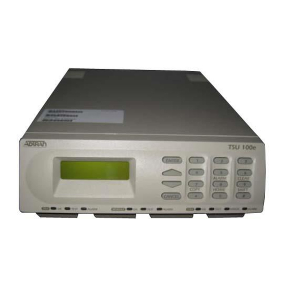
Chapter 3 FRONT PANEL The TSU 100 front panel monitors operation and controls the configuration of the unit. The TSU 100 Front Panel is shown in Figure 3-1 on page 3-3. Descriptions of each part of the front panel follow. -
Page 36: Led Descriptions
Alarm . If the alarm conditions have been Shift 8 corrected, the alarm which caused the activation of the can be viewed Alarm LED under the Unit History menu. TSU 100 User Manual 61202052L1-1... -
Page 37: Figure 3-1. Tsu 100 Front Panel
Indicates errors such as BPV, OOF or CRC. Home Returns to the main menu. Alarm (CSU Status) Active when an alarm condition has been detected on the network interface. Figure 3-1. TSU 100 Front Panel 61202052L1-1 TSU 100 User Manual... - Page 38 Chapter 3. Operation DSU Status LEDs The DSU status LEDs display the operational condition of the Nx56/64 included in the TSU 100. It also reflects the status of the DBU in the TSU 100e. Name Description OK (green) Indicates the operation is in the normal mode and no errors have been detected.
- Page 39 Alarm by pressing . If the alarm conditions have been Shift+8 corrected, the alarm which caused the activation of the Alarm LED can be viewed under the Unit History menu. 61202052L1-1 TSU 100 User Manual...
-
Page 40: Operation Keys
Used in various menus to clear Data/Result fields. General Menu Operation The TSU 100 uses a multilevel menu structure containing both menu items and data fields. All menu operations and data are displayed in the LCD window. The menu items are numbered... -
Page 41: Select And Activate A Menu Item
2) NI ERRORS 3) ACTIVE ALARMS (ALARM LIST) 4)VIEW HISTORY END OF LIST 1)STATUS 5) PORT STATUS 6) REMOTE PORT 7) CLEAR PORT ALM 8) ENET STATUS Figure 3-2. Example of Basic Front Panel Menu Travel 61202052L1-1 TSU 100 User Manual... -
Page 42: Set The Data Field
See Figure 3-3 on page 3-9. To exit the Menu Field Operation or display, press as many times as required to return to the Cancel desired menu level or press to return to Shift+Home the main menu. TSU 100 User Manual 61202052L1-1... -
Page 43: Data Port Identification
The Nx is located in the slot and is the second port in that slot. The Nx56/64 port that is built into the TSU 100 is referenced as Slot 0, Port 1. On the TSU 100e, Slot 0.1 is an Nx/DBU. -
Page 44: Front Panel Menu Structure
Chapter 3. Operation Front Panel Menu Structure The TSU 100 uses a multilevel menu structure containing both menu items and data fields. All menu operations and data dis- play in the LCD window. The opening menu is the access point to all other operations. -
Page 45: Alternate Methods Of Control
• Accesses units via the local area network (TSU 100e only). T-WATCH Pro/LAN Connection To set up the TSU 100 to work with T-WATCH Pro over the LAN, follow these steps: Step Action Set the Unit ID and Passcode using the front panel. -
Page 46: Snmp
Chapter 3. Operation T-WATCH Pro EIA-232 Connection To set up the TSU 100 to work with T-WATCH Pro over a direct EIA-232 connection, follow these steps: Step Action Set the Unit ID and set a passcode using the front panel. See Unit ID Menu on page 6-5 and Change/Set a Passcode on page 6-4 for details. -
Page 47: Terminal Mode
The MIB browser issues SNMP gets/sets to the TSU 100e. Terminal Mode The TSU 100 provides the front panel menus to a VT 100-type terminal. This mode can be used to configure and monitor the unit. Initiate this mode by typing on the terminal <CTRL>... - Page 48 Chapter 3. Operation 3-14 TSU 100 User Manual 61202052L1-1...
-
Page 49: Chapter 4 Status Menu
Chapter 4 The Status Menu branch provides the ability to view the status of the TSU 100 operation. See Figure 4-1 on page 4-2. Menu flow is normally depicted from left to right. Arrows on the lower right of the screen indicate the scrolling direction to view additional menu items. -
Page 50: Figure 4-1. Complete Status Menu
0.1 Nx56/64 2) DTE STATUS 3) PORT RATE 6) REMOTE PORT 4) DBU DATA/CNTRL* 5) DBU CONTROL* 7) CLEAR PORT ALM 6) DBU STATUS* (OPTION LIST) 8) ENET STATUS *TSU 100e Figure 4-1. Complete Status Menu TSU 100 User Manual 61202052L1-1... -
Page 51: Network Performance Reports (Ni Perf Rpts)
Network Performance Reports (NI PERF RPTS) The Network Interface Performance Reports display the user copy of the performance data. The TSU 100 maintains this per- formance data on the network in compliance with ANSI T1.403 and AT&T document TR54016. The data displayed is data accumulated over the last 15 minutes and over the last 24 hours. -
Page 52: Network Interface Errors (Ni Errors)
Chapter 4. Status Menu Since only the user’s copy of performance data is cleared by the TSU 100, the data displayed here might be different from the data sent to the network as PRM data. Network Interface Errors (NI ERRORS) The NI Errors submenu displays the types of errors the Net- work Interface (NI) detects. -
Page 53: View History
The Port Status of Nx/DBU is examined as an example of how to use this item. The DBU feature is only for the TSU 100e. 61202052L1-1 TSU 100 User Manual... -
Page 54: 0.1 Nx56/64 Menu Items
DBU Data/CNTRL (TSU 100e) An asterisk (*) indicates an active status on the following lines: Transmit data to the DCE Receive data from the DCE Data carrier detect from the DCE Ring indicate for the DCE TSU 100 User Manual 61202052L1-1... -
Page 55: Remote Port
This is useful for troubleshooting communication sessions, and for verifying cabling. Characters received at remote port Unit ID received at remote port Correct CRC received Correct passcode received Characters transmitted from the remote port 61202052L1-1 TSU 100 User Manual... -
Page 56: Clear Port Alm
Chapter 4. Status Menu Clear Port Alm Clears the Link Failed alarms on option modules that have been removed from the TSU 100 chassis. ENET Status (TSU 100e) Indicates data is being transmitted from the 10BaseT port Indicates data is being received by the 10BaseT port. -
Page 57: Chapter 5 Configuration Menu
Configuration Menu Chapter 5 The Configuration Menu sets the TSU 100 operational configu- ration, including all network interface parameters, the alloca- tion of the DS0s, and the port parameters. See Figure 5-1, Complete Configuration Menu on page 5-2. Menu flow is normally depicted from left to right. Arrows on the lower right of the screen indicate the scrolling direction to view additional menu items. -
Page 58: Figure 5-1. Complete Configuration Menu
6) RETRY DELAY 7) NUM RETRIES 8) BACKUP TESTING 1)BACKUP TEST 9) WKEND LOCKOUT 2) TEST HOUR A) ENABLE HR 3) TEST DAY B) DSABLE HR C) TRAP IN DBU Figure 5-1. Complete Configuration Menu TSU 100 User Manual 61202052L1-1... -
Page 59: Network (Ni)
Choices: Off, On. Selects the clock source for transmission toward the TIMING MODE network from the NI. See TSU 100 Clock Sources on page 5-5. Choices: Network, Base DTE (Slot 1), Normal (CSU), U-BR1TE (Slot 1), Internal, and Secondary (SI). - Page 60 Description SET LBO Selects the line build out for the network interface. In Auto mode, the TSU 100 sets the LBO based on the strength of the receive signal and displays the selected value. Choices: 0.0 dB, 7.5 dB, 15 dB, 22 dB, Auto.
-
Page 61: Tsu 100 Clock Sources
Chapter 5. Configuration Menu TSU 100 Clock Sources The TSU 100 is operable from various clock sources permitting it to perform properly in many different applications. Set the network interface clocking options with the clocking options set by the Network (NI) Configuration menu options. -
Page 62: Network Timed
This option is also referred to as loop timed as the transmission clock is derived from the received clock. Figure 5-2. Network Timed Clock Source TSU 100 User Manual 61202052L1-1... -
Page 63: Dte Timed
Chapter 5. Configuration Menu DTE Timed The DTE is the source of timing. The TSU 100 uses the incom- ing DTE clock to determine the transmission timing. This is typically used in applications where it is necessary to have the DTE as the primary clock source (such as limited distance line drivers). -
Page 64: Internal Timing
Chapter 5. Configuration Menu Internal Timing The TSU 100 is the source of timing. The TSU 100 is configured to use its own internal oscillator as the source of timing. Appli- cations include private line driver circuits where one end is set to network and the other to internal. -
Page 65: Secondary Timing
Chapter 5. Configuration Menu Secondary Timing The secondary interface is the source of timing. The TSU 100 uses the clock derived by the secondary interface for both transmission and re- ceive signal timing. See Figure 5-5. T1 XMIT Secondary Network... -
Page 66: Normal (Csu) Timing
The network interface and Secondary Interface Clocking Options are set by using the Network (NI) Configuration Menu Op- tions. Either a DSX-1 Option Module or a Drop and Insert Option Module must be installed in the TSU 100 for this mode to function. U-BR1TE The U-BR1TE timing selection works like Normal (CSU) except that timing is derived from the U interface on port 1.1. -
Page 67: Unit Menu
Enables or disables the transmission of trap messages. Choices: Enable, Disable Access Sets the method of connection from the TSU 100 to T-WATCH Pro/SNMP. Choices: Direct - Used if connected directly to the PC. Dial - Used when connection is through a modem. - Page 68 (10BaseT is only available in the TSU 100e) Subnet Mask Defines which part of a destination IP address is the Network number. Used along with the TSU 100 IP address to determine which nodes must be reached through the default IP Gateway.
-
Page 69: Map Exchange (Map Xchng)
FDL. Only one end needs to be set to Auto for this to work. Map In Use: A(B) This menu item controls the DS0 map the TSU 100 uses and displays the map in current use. 61202052L1-1... -
Page 70: Ds0 Map A And Ds0 Map B
M A P B Figure 5-7. DS0 Map Designations Map A and Map B are the current maps the TSU 100 uses. The Temp map generates a map before putting it into use. You can copy Map A to Map B by copying the Map A map into the TEMP map. - Page 71 Selecting Apply is usually the last step in updating a map and is accessed automatically at the end of editing or creating a temporary map. Currently, it can be bypassed by selecting another menu choice. 61202052L1-1 TSU 100 User Manual 5-15...
-
Page 72: Ds0 Map Example
5. Press to complete the selection and move the cursor Enter back to the DS0 field. 6. With the cursor on the DS0 field, the DS0 number can be incremented or decremented by scrolling. 5-16 TSU 100 User Manual 61202052L1-1... -
Page 73: Port Configuration (Port Config)
The list of option ports will vary with the configuration. The TSU 100 is designed so that any additional ports devel- oped in the future will contain the appropriate menu selections to provide access by use of this menu item. -
Page 74: 0.1 Nx56/64 Port Configuration Menu Items
This sets the base rate of the interface. The actual data rate depends on the number of DS0s assigned to the Nx port. Choices: 56K, 64K Controls the clock used by the TSU 100 to accept TX CLK CNTRL transmit (TX) data from the DTE. - Page 75 Choices: On, Off, On Demand This controls the source of the clock used by the TX CLK TSU 100 to accept transmit data from the DTE. SOURCE The default is Internal. If the application requires that the DTE device provides the clock with the transmit data, the External setting is used.
-
Page 76: Table 5-2. Normal Mode Of Operation
Backup occurs on RED ALARM, YELLOW ALARM, BLUE ALARM and LOS. NET/DATA FAIL Backup occurs on the same conditions as NET FAIL plus loss of data transitions on the data the NxDBU receives from the network. 5-20 TSU 100 User Manual 61202052L1-1... - Page 77 T1. Backup Test: Selects the frequency of automatic backup circuit verification by the DBU. Choices: Manual, Hourly, Daily, Weekly Test Hour: Selects the hour of the day the Backup test will occur. Choices: 0-23 61202052L1-1 TSU 100 User Manual 5-21...
- Page 78 If traps are enabled (see Unit Configuration), this Traps in DBU parameter will send either a single trap upon going into a DBU session or send repeated traps for the duration of the DBU session. Choices: Single, Repeated 5-22 TSU 100 User Manual 61202052L1-1...
-
Page 79: Chapter 6 Utility Menu
At every level of the menu, press to return the system to the previous menu level. Cancel Repeatedly pressing returns the system to the Main Cancel Menu. 61202052L1-1 TSU 100 User Manual... -
Page 80: Figure 6-1. Complete Utility Menu Tree
4) UNIT ID 5) PORT UTILITY (Displays Current Software Revision 6) SOFTWARE REV 0.1 Nx/DBU (DBU in TSU 100e) 7) ENET ADDRESS (OPTION PORTS) 8) SERIAL NUMBER 9) CMD MODE Figure 6-1. Complete Utility Menu Tree TSU 100 User Manual 61202052L1-1... -
Page 81: Time/Date
Chapter 6. Utility Menu Time/Date This menu option displays or edits the current time and date. The TSU 100 maintains the time and date during power-off conditions. If you want to... Do this... Record the entry and Press after any numeric change... -
Page 82: Change/Set A Passcode
To make changes in the configuration, the passcode can be reentered. Lost Passcode If the passcode number is lost, contact ADTRAN Customer Ser- vice for assistance. No Passcode Desired At the New Passcode prompt (in the Set Passcode menu), press without any numerical entry. -
Page 83: Unit Id Menu
This menu provides access to the display of the current soft- ware information for each port installed in the unit. This infor- mation is required when requesting assistance from ADTRAN customer service or when updates are needed. Software Revision (Software Rev) This menu provides access to the display of the current soft- ware revision level loaded into the base unit controller. -
Page 84: Enet Address (Tsu 100E)
Chapter 6. Utility Menu ENET Address (TSU 100e) Displays the Ethernet address for the 10BaseT port. Serial Number Displays the serial number of the unit. CMD Mode Reserved for factory use. TSU 100 User Manual 61202052L1-1... -
Page 85: Chapter 7 Test Menu
At every level of the menu, press- returns the system to the previous menu level. Cancel Repeatedly pressing returns the system to the Main Cancel Menu. 61202052L1-1 TSU 100 User Manual... -
Page 86: Network Tests
Test results display in the LCD window. Executing Network Tests will disrupt normal data flow unless only TST DS0s are selected for testing. TSU 100 User Manual 61202052L1-1... -
Page 87: Loopback Tests
Similar to line loop-back, except that the framing is extracted from the received data and then regenerated for the transmit- ted data. TSU 100 NI CSU Secondary Interface Payload Loopback Line Loopback Figure 7-2. Network Loopback Tests 61202052L1-1 TSU 100 User Manual... -
Page 88: Local Loopbck
Initiates the transmission of a FT1 loop- back using the inband code described in T1.403. No loop-back Deactivates the loop-back Remote loop-back can only be used with Fractional T1 if the FT1 LPBK is selected. TSU 100 User Manual 61202052L1-1... -
Page 89: Test Patterns
Chapter 7. Test Menu After a Remote loop-back option is selected, the TSU 100 ver- ifies that the far end is actually in a loop-back by checking for the receipt of a code looped back from the far end. Once the... -
Page 90: Pattern Result
Chapter 7. Test Menu Example: Select QRSS ALL DS0s by using the arrow keys Press to record the selection. The TSU 100 generates a Enter QRSS test pattern and inserts the pattern into all DS0s. Select None to end the test. Pattern Result Displays the results of the test currently active. -
Page 91: Run Selftest
LEDs are illuminated. Test failures are displayed in the LCD window. The self-test consists of the following tests: Board Level Tests Each of the TSU 100 boards contain an on board processor which executes a series of tests checking the circuitry on the board. -
Page 92: Port Tests
PRT/LCL loop-back upon detection of the V.54 code. The loop is deactivated. The TSU 100 checks the remote loop-back activation by detecting a proper response from the remote end. While waiting for the re- sponse, the display shows Looping. If successful, the display changes to Looped-Up. - Page 93 INTERFACE TST Causes the external DCE to dial its stored number. After the connection is established, the DBU sends a test pattern to verify the backup network. This test does not disrupt data or the primary network. 61202052L1-1 TSU 100 User Manual...
-
Page 94: Cancel Tests
When an interface test is active, this screen will show the total number of DATA blocks received and the number of blocks with errors. Cancel Tests Use this menu selection to deactivate all active tests, including tests on option modules. 7-10 TSU 100 User Manual 61202052L1-1... -
Page 95: Chapter 8 Telnet/Terminal Menus
MAIN MENU The TELNET/Terminal Main Menu is the first menu displayed after the TELNET/Terminal session is established (see Figure 8-1). The default TELNET/Terminal password is ADTRAN. Only one TELNET/Terminal session may be active at a time. ADTRAN - TSU 100... -
Page 96: Status, Config, Util, And Test Menu Options
4) REVIEW MAP A 5) REVIEW MAP B 6) REVIEW TEMP MAP 7) EDIT TEMP MAP 8) APPLY TEMP MAP TO MAP A 9) APPLY TEMP MAP TO MAP B Figure 8-2. DS0 Temp Map TSU 100 User Manual 61202052L1-1... - Page 97 1 through 3 three configurations. the Temp Map from its current 1 and 2 configuration to one which reflects the currently stored Map A or B configurations, respectively. the Temp Map to an all IDLE state. 3 61202052L1-1 TSU 100 User Manual...
- Page 98 Selections 8 or 9 to apply this configuration to Map A or B, respectively. Reviewing Maps Selections 4 through give a summary of the number of ports assigned to Map A, Map B, and the Temp Map, respectively. TSU 100 User Manual 61202052L1-1...
-
Page 99: Remote Menu Access
Remote Menu Access Remote Menu Access displays TELNET menus for a remote device. This may be another TSU/TDU or any other ADTRAN product that supports TELNET via its EIA-232 chain port. After selecting this option, the user may choose to connect to a device entered in the Unit Access Table or enter a Unit ID for a unit not in the Unit Access Table. -
Page 100: Figure 8-3. Unit Access Table
FDL, traps are not automatically forwarded. • Polling must be enabled on the TSU 100 for these units in or- der to receive Traps on the NMS. The TSU 100 can be con- figured to poll selected units for traps by enabling the polled option when adding or modifying a unit entry. -
Page 101: Snmp Read Community
MIB objects (defaults to pri- vate). • This setting must be the same value on both the TSU 100 and the NMS in order for the NMS to have read/write ac- cess to MIBS supported by the TSU 100. -
Page 102: Snmp Trap Community
Chapter 8. Telnet/Terminal Menus To access other units external to the TSU 100 (proxied units) us- ing an SNMP MIB browser, append a period and the Unit ID of the external device to the Read Only and Read/Write community name used in the MIB Browser, for example public.4. See Appen- dix A, Understanding SNMP on page A-1 for more information. - Page 103 (for example, SECOND FLOOR PBX ROOM). Auth. Fail Traps Sent (DISABLED, ENABLED: defaults to DISABLED). When enabled, the TSU 100 issues an SNMP trap when any SNMP request is received with an invalid community name. Can be used for security purposes.
-
Page 104: Flash Download
Chapter 8. Telnet/Terminal Menus Flash Download The TSU 100 uses flash memory that allows software updates via the EIA-232 port. This menu selection allows you to manu- ally perform a flash download using XMODEM. T-Flash is also available to automate this process. -
Page 105: Appendix A Understanding Snmp
This is a control program that responds to queries and com- mands from the network manager and returns requested infor- mation or invokes configuration changes initiated by the manager. It resides in each network device. 61202052L1-1 TSU 100 User Manual... - Page 106 SetRequest This command writes information to a network device. Messages The network device issues two types of messages: GetResponse and Trap. GetResponse This message is the response to a network manager GetRequest or GetNextRequest command. TSU 100 User Manual 61202052L1-1...
- Page 107 By default, SNMP MIB Browser access to the TSU 100 IP address with the configured community names, accesses the host. The TSU 100 can also act as an SNMP proxy agent for external units. To access MIB variables on externally chained devices, append a period and the Unit ID of the device to the Read and Read/Write community names.
- Page 108 SNMP traps and forwarded to the con- figured NMS. The source of the trap is uniquely identified at the NMS by a combination of the IP address of the TSU 100, and the Unit ID of the sending device. The Unit ID is present in...
-
Page 109: Table A-1. How To Configure Network Manager Mib
Action Load the desired product MIBs on the network management station. If, for example, the administrator is managing TSU 100 and ISU 512 devices, load TSU 100.MIB, ISU512.MIB, and RFC1406.MIB. Create device entries in the NMS database for all units that are to be managed through the TSU 100. - Page 110 Appendix A. Understanding SNMP TSU 100 User Manual 61202052L1-1...
-
Page 111: Appendix B Understanding
Other alarms normally reported by the TSU 100 will also be placed in history. • Each TSU 100 needs to be configured as the A SHELF, as it is provi- sioned as a separate entity. • All alarms will refer to A SHELF when received from TSU 100. - Page 112 ALARM, A SHELF ALARM are sent across the Data Link. Loss of Signal The TSU 100 will send MINOR ALARM and the A SHELF ALARM for 2.5s when it quits receiving a signal from the far end. It will also report TR-08 DL Down and LOS in the history.
- Page 113 Appendix B. Understanding TR-08 TR-08 DS0 Conversion Table The following table contains the mapping conversions needed to map voice ports to the TR-08 network. TR-08 DS0 Conversion Table Table B-2. TR-08 Channel Number Port 61202052L1-1 TSU 100 User Manual...
- Page 114 Appendix B. Understanding TR-08 TSU 100 User Manual 61202052L1-1...
-
Page 115: Appendix C. Network Pinouts
Network Pinouts Appendix C WIRING Network On the rear panel of the TSU 100 is an eight-position modular jack labeled NETWORK. This connector is used for connecting to the network. See Table B-1 for the pinout for the network connector. -
Page 116: Table C-2. Control In/Chain In Pinout
Control In/Chain In This is used as an EIA-232 port for connection to a computer or modem (Control In) or to another TSU 100 or TSU 100 (Chain In). See Table B-2 for the pinout for the control/chain-in con- nector. -
Page 117: Table C-3. Chain Out Pinout
Appendix C: Network Pinouts Chain Out This is used to connect to another TSU 100 chain-in connector. See Table B-3 for the pinout for the chain-out connector. Chain-Out Connections The chain-out connections are as follows: Connector type RJ-48 Part number AMP# 555164-2 Table C-3. -
Page 118: Table C-4. V.35 Pinout - Nx/Dbu Dte (Dbu Is Tsu 100E Only
Transmitted data (TD-B) from DTE TX clock (TC-A) TX clock (TC-B) External TX clock (ETC-A) from DTE External TX clock (ETC-B) from DTE NN, K — Test mode (TM) to DTE *(ignored by TSU 100) TSU 100 User Manual 61202052L1-1... -
Page 119: Table C-5. 10Baset Ethernet (Tsu 100E Only
10BaseT is used to connect the TSU 100e to the local area net- work. See Table B-5. 10BaseT Connections The required wiring connections are: Connector Type (USOC) RJ-45 Part number AMP # 555164-1 Table C-5. 10BaseT Ethernet (TSU 100e only) Name (To NIC) 61202052L1-1 TSU 100 User Manual... - Page 120 Appendix C: Network Pinouts TSU 100 User Manual 61202052L1-1...
-
Page 121: Appendix D. System Messages
System Messages Appendix D This appendix lists and defines the alarm and status messages that appear on the TSU 100 screen. ALARM MESSAGES Network Interface (NI) Red Alarm NI unable to frame align with incoming signal Yellow Alarm Remote alarm indication (RAI) being received... - Page 122 Sending 511 pattern towards the network interface Data is no longer looped back at the network Loop Down interface or DTE interface No longer sending 511 pattern towards the net- 511 Pattern Off work interface TSU 100 User Manual 61202052L1-1...
-
Page 123: Appendix E. Specifications
Test Jacks Bantam jacks: TX and RX (to Network) and Compatibility Pub 62411 T1 Interface ESF Format Interface TR. 194 ESF Performance Monitoring TR. 54016 and T1.403 Approvals FCC Part 15 FCC Part 68 UL 1950 61202052L1-1 TSU 100 User Manual... - Page 124 Chain In/Out Ports Interface Devices PC Serial Port, Modem or SLIP connection to router Interface Type EIA-232 Data Rates 9600, 2400, 1200, 2400, 4800, 9600, 19200, 38400 Data Format EIA-232 N81 Protocols TWATCH/ADLP, ATEL/ADLP, TCP/IP/SLIP RJ-45 Connector TSU 100 User Manual 61202052L1-1...
- Page 125 Network: IP Transport: TCP, UDP Service: SNMP, TELNET, ICMP, ARP, PING, T-WATCH Option Slot Interface Interface ADTRAN proprietary, accepts standard TSU Option Modules. Chassis Specifications Height Less than 3.5 inches (will fit in a 2U rack mount opening) Two units will fit within a 19-inch rack...
- Page 126 Appendix E. Specifications TSU 100 User Manual 61202052L1-1...
- Page 127 AUTO, map exchange menu item active alarms 4-4 5-13 Add New Unit, to unit access table 8-6 adProdPhysAddress A-4 ADTRAN anonymous ftp site A-5 bit stuffing, network menu item 5-4 ADTRAN PC management program, Blue Alarm, network interface alarm T-WATCH Pro 3-11...
- Page 128 Clear, operation key, front panel 3-6 DS0 Map A and DS0 Map B 5-14 Clock Slip, Nx56/64 interface D-1 DS0 Map, Example 5-16 clock sources, TSU 100 5-5 DS0 Maps Configuration Menu, for CMD Mode, utility menu 6-6 telnet/terminal menus 8-2...
- Page 129 LED Descriptions, TSU front panel 3- Front Panel Menu Structure 3-10 Front Panel, menu tree 3-7 Line Code, T1/FT1 interface E-1 front panel, TSU 100, description of 3- line loopback 7-3 Line On, network interface D-2 FT1 Line Rate, T1/FT1 interface E-1...
- Page 130 %AS, %EF, ES, SES, UAS 4-3 passcode, how to disable 6-4 Network Test Interface, TSU 100 2-5 passcode, using T-WATCH-Pro 6-3 Network Tests, test menu 7-2 payload loopback 7-3 Network Timed, TSU clock source 5-6...
- Page 131 SNMP, Basic Components A-1 remote port status, RX, ID, CRC, PC, SNMP, Messages A-2 TX 4-7 SNMP, using with TSU 100 3-12 repair and return information xii software revision, utility menu 6-5 Review Map A (B), DS0 menu item 5-...
- Page 132 TSU Option Modules 1-3 TSU unit, power connection 2-2 T1 Line Rate, T1/FT1 interface E-1 T-WATCH Pro, EIA-232 Connection T1/FT1 Interface E-1 3-12 Telnet, connecting to TSU 100 3-13 T-WATCH Pro/LAN Connection telnet/terminal main menu, about 8-1 3-11 Telnet/Terminal Password 8-9 T-WATCH-Pro 3-11...
- Page 133 Index alarm D-1 Y2K Compliance iii yellow alarm, network menu item 5-3 Y2K Project Line iii Y2K, Faxback Document Line iii Yellow Alarm, network interface Zeros Alarm, Nx56/64 interface D-1 61202052L1-1 TSU 100 User Manual Index-7...
-
Page 134: Index
Index Index-8 TSU 100 User Manual 61202052L1-1... - Page 135 Technical Support (888) 4ADTRAN Repair and Return If ADTRAN Technical Support determines that a repair is needed, Technical Support will coordinate with the Customer and Product Service (CaPS) department to issue an RMA number. For informa- tion regarding equipment currently in house or possible fees associ-...