Advertisement
Quick Links
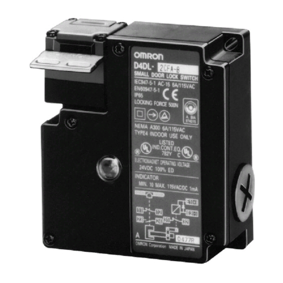
Compact Guard-locking Interlock Safety Door Switch
Polymer housing, IP65, and slow-action contacts
with positive opening
2 versions
Mechanical lock/Solenoid release
Solenoid lock/Mechanical release
Rotatable operating head provides four possible
key entry slots.
Incorporates an indicator that shows operation
status at a glance.
Double-insulation structure requires no grounding
terminals. (with
www.DataSheet4U.com
Three types of Operation Key are available:
Horizontal mounting
Vertical mounting
Angle-adjustable vertical mounting
Safety Standards
Conformity:
Machinery Directive, Low-voltage Directive, EN1088, SUVA
Approval:
Agency
TÜV Rheinland
BIA
UL (see note)
SUVA
Note: Approval for CSA C22.2 No. 14 is authorized by
Ordering Information
Model Number Legend
Switches
D4DL-jjjj-j
1
1.
Conduit Size (2-conduit)
1:
Pg13.5
1
2:
G
/
2
2.
Built-in Switch (with Safety Switch and Lock Monitor
Switch Contacts)
C:
1NC/1NO slow-action contacts plus 1NC slow-action
contact
D:
2NC slow-action contacts plus 1NC slow-action contact
3.
Head Mounting Direction
F:
Front
.
mark)
Standard
EN60947-5-1
EN60947-5-1,
GS-ET-19
UL508, CSA C22.2
No.14
SUVA
2
3
4
5
File No.
J9650736
9610568
E76675
Pending
u
mark.
c
4.
Door Lock and Release
A:
B:
C:
G:
H:
J:
5.
Indicator
B:
E:
Mechanical lock / 24-VDC solenoid release (see note)
Mechanical lock / 110-VAC solenoid release
Mechanical lock / 230-VAC solenoid release
24-VDC solenoid lock / mechanical release (see note)
110-VAC solenoid lock / mechanical release
230-VAC solenoid lock / mechanical release
10 to 115 VAC/VDC (with orange LED indicator)
100 to 250 VAC (with orange neon lamp indicator)
D4DL
E
c
1
Advertisement

Related Manuals for Omron D4DL


Summary of Contents for Omron D4DL
- Page 1 D4DL Compact Guard-locking Interlock Safety Door Switch Polymer housing, IP65, and slow-action contacts with positive opening 2 versions Mechanical lock/Solenoid release Solenoid lock/Mechanical release Rotatable operating head provides four possible key entry slots. Incorporates an indicator that shows operation status at a glance.
- Page 2 D4DL D4DL Operation Keys D4DS-Kj Key Type Horizontal mounting Vertical mounting Horizontal-adjustable vertical mounting Vertical/Horizontal-adjustable vertical mounting Switches Solenoid voltage/indicator Lock and release Contact configuration Connector size Model types (Slow-action) Approved force-separation NC contact Solenoid: 24 VDC So e o d...
-
Page 3: Specifications
Note: 1. The above values are initial values. 2. Although the switch box is protected from dust or water penetration, do not use the D4DL in places where foreign material may penetrate through the key hole on the head, otherwise switch damage or malfunctioning may occur. - Page 4 D4DL D4DL Solenoid Characteristics Item 24 VDC 110 VAC 230 VAC +10% Rated operating voltage 24 VDC (100% ED) 110 VAC 10% (100% ED) 230 VAC 10% (100% ED) –15% Current consumption Approx. 200 mA Approx. 50 mA Approx. 30 mA Insulation Class F (130 C max.)
-
Page 5: Operation Principles
D4DL D4DL Operation Operation Principles Guard Inside equipment Door closed Lock spring Power to solenoid Access to machine is not allowed. www.DataSheet4U.com Door can be opened. Lock spring locks the door. Lock releasing spring Door opened Access to machine is allowed. -
Page 6: Internal Circuit Diagram
The 24-VDC solenoid has polarity. Be sure not to make wiring mistakes. In the following connection example, the indicator will be lit when Constant-current diode the door is open. (D4DL-1CFA-B) Power supply side Neon Lamp Type (100 to 250 VAC) Neon lamp (orange) Solenoid R=130 KΩ... - Page 7 D4DL D4DL Connection Example with OMRON G9S Safety Relay Unit G9S-321-Tj (24 VDC)+D4DL-jCFA-j/-jCFB-j/-CFC-j (Mechanical Lock Type)+D4D-j520N Circuit Diagram Product Configuration PC output Motor control system Operation instruction PC output A22E D4DL Contactor (off delay) www.DataSheet4U.com Contactor (off delay) Closed D4DN...
- Page 8 D4DL D4DL G9S-301 (24 VDC)+D4DL-jCFG-j/-jCFH-j/-jCFJ-j (Solenoid Lock Type)+D4D-j520 N Circuit Diagram Product Configuration PC output Motor control system Operation instruction A22E D4DL output Closed Contactor Contactor D4DN www.DataSheet4U.com Reset switch Open Feed back loop PC output (Stop signal) E SW...
- Page 9 D4DL D4DL Dimensions Note: All units are in millimeters unless otherwise indicated. Switch Four, head mounting screw D4DL-jjjj-j Pre-travel distance Three, 4.3-dia. holes www.DataSheet4U.com Indicator Conduit cap Three, cover counting screws Release key Conduit opening Operating characteristics Model Key insertion force 14.71 N {1,500 gf} max.
- Page 10 D4DL D4DL Operation Key Inserted D4DL + D4DS-K1 D4DL + D4DS-K2 D4DL + D4DS-K3 Horizontal Horizontal Horizontal 40 min., 42.5 max. 44 min., 46.5 max. 45 min., 47.5 max. insertion radius: insertion radius: insertion radius: Key inserting Key inserting Key inserting...
- Page 11 Life Expectancy To protect the D4DL from damage due to short-circuits, connect the D4DL in parallel to a fuse that has a breaking current 1.5 to 2 times The life of the D4DL will vary with the switching conditions. Before the rated current of the D4DL.
- Page 12 Furthermore, the door may not unlocked if force is imposed on the operation key. Do not use the casing of the D4DL as a locking mechanism for the door in such cases and be sure to prepare a special lock within the lock range of the D4DL (i.e., 0.5 to 3 mm).
- Page 13 Be sure that the diameter of the cable connected to the connector is correct. www.DataSheet4U.com Two, M4 Attach and tighten a conduit cap to the unused conduit opening when wiring the D4DL. The conduit cap is provided with the D4DL. Recommended Connectors Size Manufacturer Model...
- Page 14 D4DL D4DL www.DataSheet4U.com...
- Page 15 D4DL D4DL www.DataSheet4U.com...
- Page 16 D4DL D4DL www.DataSheet4U.com ALL DIMENSIONS SHOWN ARE IN MILLIMETERS. To convert millimeters into inches, multiply by 0.03937. To convert grams into ounces, multiply by 0.03527. Cat. No. C107-E1-2 In the interest of product improvement, specifications are subject to change without notice.