Advertisement
Quick Links
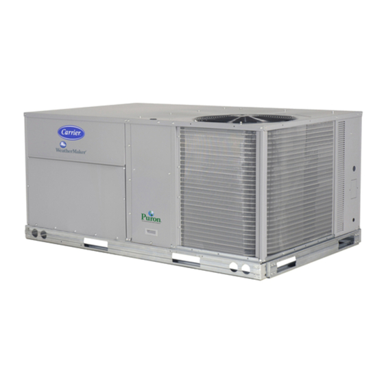
CRECOMZR067A00
CRECOMZR069A00
CRECOMZR071A00
Read these instructions completely before attempting to install the
Vertical EconoMi$er X Accessory.
CONTENTS
SAFETY CONSIDERATIONS . . . . . . . . . . . . . .1
GENERAL. . . . . . . . . . . . . . . . . . . . . . . . . . . . . 1
EconoMi$er X Sensor Usage . . . . . . . . . . . . . 2
ACCESSORIES LIST. . . . . . . . . . . . . . . . . . . . .2
INSTALLATION . . . . . . . . . . . . . . . . . . . . . . . 2-5
EconoMi$er X Standard Sensors . . . . . . . . . .5
EconoMi$er X Control Modes . . . . . . . . . . 5-11
OPERATION . . . . . . . . . . . . . . . . . . . . . . . . . . 12
TROUBLESHOOTING . . . . . . . . . . . . . . . . . . 13
SAFETY CONSIDERATIONS
Improper installation, adjustment, alteration, service, maintenance, or
use can cause explosion, fire, electrical shock or other conditions which
may cause personal injury or property damage. Consult a qualified
installer, service agency, or your distributor or branch for information or
assistance. The qualified installer or agency must use factory-authorized
kits or accessories when modifying this product. Refer to the individual
instructions packaged with the kits or accessories when installing.
Follow all safety codes. Wear safety glasses and work gloves. Use
quenching cloths for brazing operations and have a fire extinguisher
available. Read these instructions thoroughly and follow all warnings
or cautions attached to the unit. Consult local building codes and
appropriate national electrical codes (in USE, ANSI/NFPA70, National
Electrical Code (NEC); in Canada, CSA C22.1) for special requirements.
It is important to recognize safety information. This is the safety-alert
symbol
. When you see this symbol on the unit and in instructions or
!
manuals, be alert to the potential for personal injury.
Understand the signal words DANGER, WARNING, CAUTION, and
NOTE. These words are used with the safety-alert symbol.
DANGER identifies the most serious hazards which will result in severe
personal injury or death. WARNING signifies hazards which could
result in personal injury or death.
CAUTION is used to identify unsafe practices, which may result in
minor personal injury or product and property damage.
NOTE is used to highlight suggestions which will result in enhanced
installation, reliability, or operation.
WARNING
!
ELECTRICAL SHOCK HAZARD
Failure to follow this warning could cause personal injury or death.
Before performing service or maintenance operations on the unit,
always turn off main power switch to unit and install lock(s) and
lockout tag(s). Unit may have more than one power switch. Ensure
electrical service to rooftop unit agrees with voltage an amperage
listed on the unit rating plate.
CAUTION
!
CUT HAZARD
Failure to follow this caution may result in personal injury.
Sheet metal parts may have sharp edges or burrs. Use care and wear
appropriate protective clothing, safety glasses and gloves when
handling parts and servicing roof top units.
Installation Instructions
1
Vertical EconoMi$er X Accessory
GENERAL
The EconoMi$er X system utilizes the latest technology available
for integrating the use of free cooling with mechanical cooling for
packaged rooftop units. The solid-state control system optimizes energy
consumption, zone comfort, and equipment cycling by operating the
compressors when the outdoor-air temperature is too warm, integrating
the compressor with outdoor air when free cooling is available, and
locking out the compressor when outdoor-air temperature is too cold.
Demand control ventilation is supported.
Units displaying 17th position of the model number to indicate that the
unit is equipped with the factory-installed VFD (Variable Frequency
Drive) option for 2-speed indoor fan control. The VFD option is required
for units equipped with EconoMi$er X. For detailed information on the
VFD see the Variable Frequency Drive (VFD) Installation, Setup and
Troubleshooting Supplement.
The EconoMi$er X system utilizes gear-drive technology with a direct-
mount spring return actuator that will close upon loss of power. The
EconoMi$er X system comes standard with an outdoor air temperature
sensor, mixed air temperature sensor. Outdoor enthalpy, indoor enthalpy,
and CO2 sensors are available for field installation. See Table 3 for
sensor usage.
IMPORTANT: The economizer outside air dampers meet the ASHRAE
90.1 leakage requirements. Economizer must be installed perfectly
square to avoid damper leakage. Squareness tolerance +/- 1/32".
Standard barometric relief dampers provide natural building pressurization
control. An optional power exhaust system is available for applications
requiring even greater exhaust capabilities. The power exhaust set point
is adjustable at the EconoMi$er X controller.
See Table 1 for package usage. See Table 2 for package contents. See
Table 3 for sensor usage.
ACCESSORIES LIST
Table 1 - Package Usage
UNIT SIZE
Small Cabinet,
Footprint size: 46 3/4" x 74 3/8"
Large Cabinet,
Footprint size: 58 1/2" x 88 1/8"
Extra-Large Cabinet,
Footprint size: 63 3/8" x 115 7/8"
Table 2 - Package Contents
PACKAGE NO.
QTY
CRECOMZR067A00,
CRECOMZR069A00
18
CRECOMZR071A00
Small Rooftop Products
3 to 12 ½ Tons
PART NUMBER
CRECOMZR067A02
CRECOMZR069A03
CRECOMZR071A00
CONTENTS
1
Hood Top and Sides
1
Hood Divider
1
Aluminum Filter
Screws
1
EconoMi$er X Assembly
1
Mixed Air Temperature Sensor
1
Hood Top and Sides
1
Hood Divider
1
Hood Filter Divider
2
Aluminum Filters
1
Hardware Bag
1
EconoMi$er X Assembly
1
Mixed Air Temp Sensor
Advertisement

Related Manuals for Carrier CRECOMZR067A00


Summary of Contents for Carrier CRECOMZR067A00
- Page 1 Small Rooftop Products CRECOMZR067A00 3 to 12 ½ Tons CRECOMZR069A00 Vertical EconoMi$er X Accessory CRECOMZR071A00 Installation Instructions GENERAL Read these instructions completely before attempting to install the Vertical EconoMi$er X Accessory. The EconoMi$er X system utilizes the latest technology available...
- Page 2 Remove the existing unit filter access panel. Raise the panel and Table 3 - EconoMi$er X Sensor Usage swing the bottom outward. The panel is now disengaged from the ECONOMI$ER X WITH OUTDOOR AIR track and can be removed. (See Fig. 2.) DRY BULB SENSOR APPLICATION Remove the indoor coil access panel and discard.
- Page 3 Flanges Hood Divider Fig. 3 - Hood Assembly Fig. 5 - EconoMi$er X Installed in HVAC Unit (3 to 6 Ton Shown) ECONOMIZER P/N SHIP WT. CRECOMZR067A00 33.37” 17.43” 19.05” 29.5” 55 lb CRECOMZR069A00 40.37” 22.28” 24.48” 36.27” 80lb CRECOMZR071A00 52.92”...
- Page 4 14. While everything is open install and wire any other accessories and/or sensors as applicable and convenient, per their installation instructions and/or the Configuration section of this instruction. Some accessories require that unit ducting already be installed. W7220 Controller NOTE: If also installing a power exhaust accessory, skip step 16 and follow the power exhaust instructions instead.
- Page 5 Thermostat Center Post Connection Access Panel Heating Access Indoor Fan Motor Panel Access Panel Fig. 9 - Typical Indoor Fan Motor Access Panel Locations Fig. 11 - W7220 Controller Keypad The four navigation button (see Fig. 3) are used to scroll through the menus and menu items, select menu items, and to change parameter and Supply Air configuration settings.
- Page 6 IMPORTANT: Table 5 illustrates the complete hierarchy. Your menu parameters may be different depending on your configuration. For example if you do not have a DCV (CO ) sensor, then none of the DCV parameters appear. Table 5 ─ Menu Structure Parameter Parameter Menu...
- Page 7 Table 5 ─ Menu Structure (cont) Parameter Parameter Menu Parameter Default Notes Range and Increment Value SETPOINTS MAT SET 38 to 65 Setpoint determines where the economizer will modulate the OA increment by 1 damper to maintain the mixed air temperature. LOW T LOCK -45 to 80 Setpoint determines outdoor temperature when the mechanical cooling...
- Page 8 Table 5 ─ Menu Structure (cont) Parameter Parameter Menu Parameter Default Notes Range and Increment Value SYSTEM FACTORY DEFAULT NO or YES Resets all set points to factory defaults when set to YES. LCD will SETUP briefly flash YES and change to NO but all parameters will change to the factory default values.
- Page 9 Table 6 - Economizer Module - Checkout Tests Left Hand Terminal Blocks Use the Checkout menu (see Table 5 on page 6) to test the damper op- Label Type Description eration and any configured outputs. Only items that are configured are shown in the Checkout menu.
- Page 10 Fig. 13 - Single Enthalpy Curve boundaries Table 8 - Single Enthalpy and Dual Enthalpy High Limit Curves Point P1 Point P2 Enthalpy Temp. Temp. Enthalpy Humidity Curve Dry Bulb ( Dewpoint ( (btu/lb/da) Temp ( Humidity %RH Temp ( 80.0 60.0 28.0...
- Page 11 When free cooling is available as determined by the appropriate change- over command (dry bulb, outdoor enthalpy, differential dry bulb or dif- ferential enthalpy), a call for cooling (Y1 closes at the thermostat) will cause the economizer control to modulate the dampers open and closed to maintain the unit supply air temperature at 50 to 55 F.
- Page 12 Table 11 - Damper Position Control, 2-Speed Fan Motor, Economizer Cooling Not Available INPUT 0 - V 24 - V 24 - V 24 - V 24 - V 0 - V 0 - V 24 - V 24 - V 0 - V 0 - V 0 - V...
- Page 13 Table 12 - Operating Issues and Concerns Issue or Concern Possible Cause and Remedy My outdoor temperature reading on the Check the sensor wiring: STATUS menu is not accurate • Enthalpy sensors are to be wired to the S-Bus terminals. •...
- Page 14 Copyright 2012 Carrier Corporation ● 7310 W. Morris St. ● Indianapolis, IN Edition Date: 5/12 Catalog No. IIK-CRECOMZR67-01 Replaces: New Manufacturer reserves the right to discontinue, or change at any time, specification or designs without notice and without incurring obligations...