Table of Contents
Advertisement
Quick Links
T hank you for choosing Air Conditioners, please read this owner's manual carefully before operation and
retain it for future reference. If you have lost the Owner's Manual, please contact the local agent or visit
www.gree.com or sent email to global@gree.com.cn or electronic version.
GREE reserves the right to interpret this manual which will be subject to any change due to product
i m p r o v e m e n t without further notice.
G REE Electric Appliances, Inc. of Zhuhai reserves the final right to interpret this manual.
Ultra Heat GMV Multi VRF
R410A Systems ― Outdoor Unit
Owner ' s Manual
Air Conditioners
GMV-V72W/A-F(U)
GMV-V96W/A-F(U)
GMV-V192WM/A-F(U)
Advertisement
Table of Contents

Related Manuals for Gree Ultra Heat GMV Multi VRF Series


Summary of Contents for Gree Ultra Heat GMV Multi VRF Series
- Page 1 GREE reserves the right to interpret this manual which will be subject to any change due to product i m p r o v e m e n t without further notice.
- Page 2 Preface Gree Ultra Heat GMV Multi VRF System, with the most advanced technologies in the world, uses eco-friendly refrigerant R410A as its cooling medium. For correct installation and operation, please read this manual carefully. This is the safety alert symbol. It is used to alert you to potential personal injury hazards. Obey all safety messages that follow this symbol to avoid possible injury or death.
- Page 3 Exception Clauses Manufacturer will bear no responsibilities when personal injury or property loss is caused by the following reasons: (1) Damage the product due to improper use or misuse of the product; (2) Alter, change, maintain or use the product with other equipment without abiding by the instruction manual of manufacturer;...
-
Page 4: Table Of Contents
Contents 1 Safety Precautions ....................... 1 2 Product Introduction ......................3 2.1 Names of Main Parts ..........................3 2.2 Combinations of Indoor and Outdoor Units .................... 3 2.3 The Range of Production Working Temperature ................... 4 3 Preparation before Installation ................... 5 3.1 Standard Parts ............................ -
Page 5: Safety Precautions
(18) Under cooling mode, please don't set the room temperature too low and keep the temperature difference between indoor and outdoor unit within 5ºC(41ºF). (19) User is not allowed to repair the unit. Fault service may cause electric shock or fire accidents. Please contact Gree appointed service center for help. - Page 6 (27) If anything abnormal happens (such as burning smell), please power off the unit and cut off the main power supply, and then immediately contact Gree appointed service center. If abnormality keeps going, the unit might be damaged and lead to electric shock or fire.
-
Page 7: Product Introduction
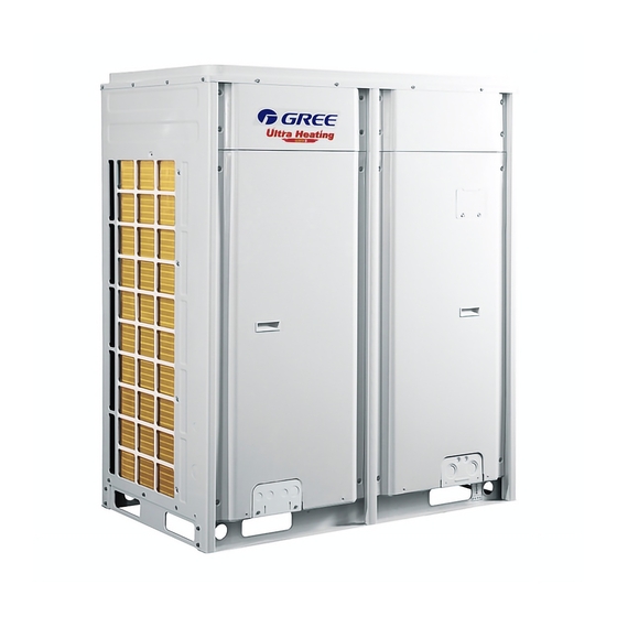
Various product lineup is provided with capacity range from 72K Btu to 192K Btu, which can be widely used in working area and especially applicable to the place with variable load change. Gree air conditioner is absolutely your best choice. -
Page 8: The Range Of Production Working Temperature
Ultra Heat GMV Multi VRF GMV-V72W/A-F(U) GMV-V96W/A-F(U) GMV-V192WM/A-F(U) The total capacity of indoor units should be within 50%~135% of that of outdoor units. While the rate is over 100% and all IDUs are on run, the units cooling or heating capacity will be wakened. Fig.2 Fig.2 is the combination view of the ODU of Ultra Heat GMV Multi VRF Modular System and the IDU of Multi VRF System. -
Page 9: Preparation Before Installation
Ultra Heat GMV Multi VRF 3 Preparation before Installation Note: The picture is only used for reference and the actual product prevails. Unit: mm (inch). 3.1 Standard Parts Please use the following standard parts supplied by Gree. Parts for Outdoor Unit Number Name... - Page 10 Ultra Heat GMV Multi VRF 1) Space dimension for single-module unit Fig.3 2) Space dimension for dual-module unit Fig.4 3.2.2 Space requirement for the top of outdoor unit When there is wall (or similar obstruction) above the unit, keep the distance between the unit top and the wall at least 3000mm (118-1/8in.) or above.
- Page 11 Ultra Heat GMV Multi VRF Fig.5 Fig.6 3.2.3 Space dimension for multiple-module unit For keeping good ventilation, make sure there are no obstructions above the unit. When the unit is located at a half-open space (front and left/right side is open), install the unit as per the same or opposite direction.
- Page 12 Ultra Heat GMV Multi VRF Fig.7...
- Page 13 Ultra Heat GMV Multi VRF Fig.8 3.2.4 Take seasonal wind into consideration when installing the outdoor unit 1) Anti-monsoon installation requirements for unit not connecting exhaust duct Fig.9...
- Page 14 Ultra Heat GMV Multi VRF Fig.10 Fig.11 3.2.5 Take snow into consideration when installing the outdoor unit Fig.12...
-
Page 15: Piping Work Requirements
Ultra Heat GMV Multi VRF 3.3 Piping Work Requirements There should be no fall among outdoor modules. Refer to the table below for piping work requirements. R410A Refrigeratn System Outer diameter (mm/inch) Wall thickness (mm) Type Φ6.35(1/4) ≥0.8 Φ9.52(3/8) ≥0.8 Φ12.70(1/2) ≥0.8 Φ15.9(5/8) -
Page 16: Installation Instruction
Ultra Heat GMV Multi VRF 4 Installation Instruction 4.1 ODU Foundation The concrete foundation of the ODU must be strong enough. Ensure that the drainage is smooth and that the ground drainage or floor drainage is not affected. Requirements on the concrete foundation are as follows: 1) The concrete foundation must be flat and have enough rigidity and strength to undertake the unit’s weight during running. -
Page 17: Physical Dimension Of The Outdoor Unit And Mounting Hole
Ultra Heat GMV Multi VRF 4.2 Physical Dimension of the Outdoor Unit and Mounting Hole Outline and physical dimension of GMV-V72W/A-F(U)、GMV-V96W/A-F(U) : Fig.14... -
Page 18: Connection Pipe
Ultra Heat GMV Multi VRF 4.3 Connection Pipe 4.3.1 Schematic Diagram of Piping Connection Module Module Branch between Gas pipe outdoor units Liquid pipe Outdoor connection pipe Connection pipe between indoor branch and indoor units Indoor unit 1 Connection pipe between indoor branchs Branch between indoor units Connection pipe between indoor branch and indoor units Indoor... - Page 19 Ultra Heat GMV Multi VRF Remark: Equivalent length of one Y-type manifold is about 0.5m (1-3/4feet). Fig.17 L10: Length from the first branch to the farthest IDU; L11: Length from the first branch to the nearest IDU; Equivalent length of branch of IDU is 0.5m (1-3/4feet). Allowable Value R410A Refrigerant System Fitting Pipe...
- Page 20 Ultra Heat GMV Multi VRF between outdoor ≤40(131-1/4) Outdoor unit at lower(2) —— unit and indoor unit ≤15(49) Height difference between indoor units —— ≤90(295-1/4) Maximum length of Main pipe(3) ≤40(131-1/4) From IDU to its nearest branch (4) a, b, c, d, e, f, g, h, i, j Notices: (1) Normally, the pipe length from the first branch of IDU to the farthest IDU is 40m (131-1/4feet).
- Page 21 Ultra Heat GMV Multi VRF Fig.19 Note: when the distance between outdoor units exceeds 2m (6-1/2 feet), U-type oil trap should be added at low-pressure gas pipe. a≤10m (32-7/8 feet); b≤10m (32-7/8 feet). 4.3.5 Size requirement for branch pipe and piping 4.3.5.1 Connection sketch map of single-module system Fig.20(a)
- Page 22 Ultra Heat GMV Multi VRF Fig.20 (b) 4.3.5.2 Connection sketch map of multi-module system Fig.21 4.3.5.3 Select appropriate pipe between outdoor unit and the first indoor branch (“L”) as per the pipe size of outdoor unit. Pipe size of basic outdoor module is shown as follows: For single module, L pipe between outdoor unit and the first indoor branch: Pipe between outdoor unit and the first indoor branch Basic module...
- Page 23 Ultra Heat GMV Multi VRF Φ31.8(1-1/4) Φ15.9(5/8) GMV-V192WM/A-F(U) 4.3.5.4 For multi-module system, select appropriate branch (“M1, M2”) connected to outdoor module as per the pipe size of basic outdoor module. Pipe between module and outdoor branch “M1, M2”: Pipe between outdoor unit and the first indoor branch Basic module Gas pipe mm(inch) Liquid pipe mm(inch)
-
Page 24: Installation Of The Connection Pipe
Ultra Heat GMV Multi VRF 4.3.5.7 Piping between branch and indoor unit (“a、c、d”) Size of connection pipe between indoor branch and indoor unit Rated capacity of indoor units: X ((Btu/h) Gas pipe mm(inch) Liquid pipe mm(inch) Φ9.52(3/8) Φ6.35(1/4) X≤9500 Φ12.7(1/2) Φ6.35(1/4) 9500<X≤17100 Φ15.9(5/8) - Page 25 Ultra Heat GMV Multi VRF 4.4.2 Manifold (1) Y-type manifold, T-type manifold. Fig.23 (a) Y-type manifold Fig.23 (b) T-type manifold (2) Y-type manifold has several pipe sections with different pipe size, which facilitates to match with various copper pipe. Use pipe cutter to cut in the middle of the pipe section with different pipe size and deburr as well.
- Page 26 Ultra Heat GMV Multi VRF Fig.24 (b) (4) Manifold is isolated by insulating material that can bear 120ºC(248℉)or higher temperature. Manifold attached foam cannot be taken as insulating material. 4.4.3 Thermal insulation for pipeline (1) For multi VRF system, every copper pipe should be labeled so as to avoid misconnection. (2) At the manifold inlet, at least leave 500mm (19-11/16inch) straight pipe section, and for FQ04 manifold, keep it at least 800mm (31-1/2inch).
- Page 27 Ultra Heat GMV Multi VRF Fig.26 (4) Suspend the header to the ceiling, and be sure to install T-type manifold so that the outlet pipes are horizontal at the lower side. Fig.27 (a) Fig.27 (b) (5) Thermal insulation for pipeline 1) To avoid condensate or water leakage on connecting pipe, the gas pipe and liquid pipe must be wrapped with thermal insulating material and adhesive pipe for insulation from the air.
-
Page 28: Air Purging And Refrigerant Charge
Ultra Heat GMV Multi VRF 2) For heat pump unit, liquid pipe should bear 70ºC(158℉) or above, and gas pipe should bear 120 ºC(248℉) or above. For cooling only unit, both liquid pipe and gas pipe should bear 70ºC(158℉) or above. Example: Polyethylene foam can bear 120ºC(248℉) above and foaming polyethylene can bear 100ºC(212℉) above. - Page 29 Ultra Heat GMV Multi VRF Fig.30 4.5.2 Additional refrigerant charging Outdoor unit has been charged refrigerant before delivery. If the pipeline is longer than 1m (39-3/8inch), please refer to the following table for charging amount of refrigerant. (Liquid pipe prevails) Total refrigerant charging amount R= Pipeline charging amount A + ∑charging amount B of every module (1) Pipeline charging amount...
- Page 30 Ultra Heat GMV Multi VRF For example: The OUD is GMV-V192WM/A-F(U) including GMV-V96W/A-F(U) and GMV-V96W/A-F(U). The IDUs are made up of 11sets of GMV-ND18PHS/A-T(U). IDU/ODU rated capacity collocation ratio C=18×11/192=103%.The quantity of included IDUs is more than 4 sets. Please refer to the above table. Refrigerant charging amount B for GMV-V96W/A-F(U) module is 3kg(6.6lbs).
-
Page 31: Electric Wiring
(4) If the maximum refrigerant concentration exceeds the allowed threshold, the refrigeration system must be redesigned. In this case, separate the refrigeration system into multiple small-capacity refrigeration systems, or contact local Gree sales company. Fig.31 1) Flow direction of refrigerant leakage. - Page 32 Ultra Heat GMV Multi VRF is required to control power supply or disconnection. Fig.32 Outdoor Unit Minimum Circuit Maximum Overcurrent Power Supply Fuse Capacity Ampacity Protection Outdoor units V/ Ph /Hz GMV-V72W/A-F(U) 208V/230V 3~ 60Hz GMV-V96W/A-F(U) 208V/230V 3~ 60Hz GMV-V192WM/A-F(U) 208V/230V 3~ 60Hz 60+60 45+45...
- Page 33 Ultra Heat GMV Multi VRF (4) The green-yellow wire within units are ground wire. Do not use it for other purposes. Nor should it be cut off or secured by tapping screws. Otherwise, it may cause electric shock. (5) Power supply at user side must have reliable ground terminal. Do not connect ground wire to the following places: 1) Water pipe.
-
Page 34: System Communication
Ultra Heat GMV Multi VRF Fig. 33 4.7 System Communication 4.7.1 Communication system include: (1) Communication among outdoor basic modules. (2) Communication between ODU and IDU. (3) Communication among IDUs. (4) Communication between IDU and wired controller. (5) Connection between IDU and light board receiver. - Page 35 Ultra Heat GMV Multi VRF (6) Communication between different refrigeration systems. (7) Graphics of general communication connection. Fig.34 4.7.2 Communication mode of Ultra Heat GMV Multi VRF Units CAN bus is taken for communication between IDU and ODU and communication among IDUS. 4.7.3 Selection and connection mode of Ultra Heat GMV Multi VRF communication material 4.7.3.1 Select communication material NOTICE! If air conditioners are installed at places where there’s strong electromagnetic...
- Page 36 Ultra Heat GMV Multi VRF For example, two wired controllers control multiple IDUs and the graphic of connection between IDU and wired controller is: Fig.35 (2)Select communication wire between ODU and IDU Total Length L(m) of Communication Cable Material Type Wire size Remarks between IDU Unit and IDU...
- Page 37 Ultra Heat GMV Multi VRF Fig.37 Fig.38 (2) All communication wires of Ultra Heat GMV are connected by screws. Terminal Bend Connection Screw Fig.39 (3) If a single communication wire is not long enough and needs to be connected, the connected joint must be welded or pressure-welded.
-
Page 38: Connection Method And Steps For System Communication
Ultra Heat GMV Multi VRF codes manually. Only the addresses of master unit and central control are needed to be set (address of central control is only needed when there are multiple refrigeration systems). NOTICE! When installing centralized controller or remote monitor, indoor units’ project codes must be displaced. - Page 39 Ultra Heat GMV Multi VRF Fig.41 Connection of communication for multi refrigeration systems: Fig.42 (1) Communication wire and power cord must be separated. (2) Communication wire must be of proper length. Extension is not allowed. (3) IDUs must be connected in series. The last IDU D1/D2 must be connected with the communication matched resistance (supplied in the list of ODU spare parts).
- Page 40 Ultra Heat GMV Multi VRF (5) For modular outdoor units, if there are multiple outdoor modules, then indoor units must be connected with the last slave module of ODU (slave module is set by S7 of the outdoor main board). (6) For modular outdoor units, if there are multiple outdoor modules, the communication matched resistance (installed before factory) of slave modules connecting with D1/D2 must be removed.
- Page 41 Ultra Heat GMV Multi VRF Fig.46 Two wired controllers control multiple IDUs When two wired controllers control multiple IDUs, the wired controllers can be connected to any one IDU, provided that the connected IDU is of the same series. Meanwhile, one and only one of the wired controllers must be set as a slave controller.
- Page 42 Ultra Heat GMV Multi VRF Fig.47 (1) Wired controller and light board remote receiver can be used at the same time. (2) When light board remote receiver is used, please use remote controller at the same time. 4.8.4 Communication connection of central controlling units NOTICE! The centralized controller can be installed when it is necessary.
-
Page 43: External Electrical Wiring Diagram
Ultra Heat GMV Multi VRF Fig.48 4.9 External Electrical Wiring Diagram WARNING (1) Each unit should be equipped with a circuit breaker for short circuit protection and exceptional overload protection. In general, circuit breaker is at OFF status. (2) During operation, all indoor units and outdoor units belonging to the same system must be kept energized status. Otherwise, the unit can’t operate normally. - Page 44 Ultra Heat GMV Multi VRF Fig.49 NOTICE! Maximum number of IDU is based upon ODU capacity. For details, please refer to the introduction of units’ combination. 4.9.2 External wiring diagram of modular connection...
- Page 45 Ultra Heat GMV Multi VRF Fig.50 NOTICE! Maximum number of ODU (N) and maximum number of IDU (n) are based upon the combination type of ODU. For details, please refer to the introduction of unit combination.
- Page 46 Ultra Heat GMV Multi VRF 4.10 Attention before operation The installer should read the following items, and make sure that the metal parts supplied for transportation are taken down. 1) For safe handling, two metal parts are fixed at the feet of compressor before delivery (shown as follows): Fig.51 2) While installation, please make sure the metal parts are taken down.
-
Page 47: Check Items After Installation And Trial Run
Ultra Heat GMV Multi VRF 5 Check Items after Installation and Trial Run 5.1 Check Items after Installation Check items Possible conditions due to improper installation Check Each part of the unit is installed securely? Unit may drop, shake or emit noise Gas leakage test is taken or not? Insufficient cooling (heating) capacity Unit gets proper thermal insulation or not? - Page 48 Ultra Heat GMV Multi VRF (6) Check the valve: fully open the gas and liquid valve. 5.2.2 Trial run 5.2.2.1 Notices (1) Before test operation, make sure unit is power on and compressor has been preheated for more than 8 hours. Touch the unit to check whether it’s normally preheated. Start test operation after unit is normally preheated, otherwise compressor might be damaged.
- Page 49 Ultra Heat GMV Multi VRF LED1 LED2 LED3 Progress Display Display Display Code Code Code status status status Light System is not debugged. Master unit hasn’t been set, please Light set it. Master unit is two or more than two. Light 01_ Set master Please reset.
- Page 50 Ultra Heat GMV Multi VRF judgments Refrigerant is normal. Next step will Light Light Light before startup start automatically. —— —— —— —— —— —— No meaning. —— —— —— —— —— —— No meaning. Light Blink Blink Ready for units to start debugging. 12_Confirm The unit starts up in the status of debugging...
- Page 51 Ultra Heat GMV Multi VRF can be seen in Master Unit Setup S7 of Technical service manual (Set master unit S7 as “00”; Set slave unit S7 as “10”); Step 4: Connect power for all indoor units. Make sure all IDUs are power on. Then all outdoor modules will display “A0”;...
- Page 52 Ultra Heat GMV Multi VRF 02_Allocate Light Light Light addresses Step 8: In progress 03, the quantity of modules needs to be confirmed manually. Main board will display: —— Debugging code Progress code Status code LED1 LED2 LED3 Progress Code Display status Code Display status...
- Page 53 Ultra Heat GMV Multi VRF LED1 LED2 LED3 Progress Display Display Display Code Code Code status status status Communication between master Light ODU and inverter compressor driver 05_Internal has error. communicatio n detection Communication between master Light ODU and IDUs has error. Elimination methods of above errors can be found in Troubleshooting.
- Page 54 Ultra Heat GMV Multi VRF —— Debugging code Progress code Status code LED1 LED2 LED3 Progress Code Display status Code Display status Code Display status 08_Confirm preheated Light Light Light compressor If the ODU valves connecting with IDU have been opened manually, then press SW4 confirmation button on the master unit to confirm it.
- Page 55 Ultra Heat GMV Multi VRF confirm the startup again. Operate as below: If master unit displays as below, system is waiting for confirmation signal. —— Debugging code Progress code Status code LED1 LED2 LED3 progress Code Display status code Display status Code Display status 12_Confirm...
- Page 56 Ultra Heat GMV Multi VRF System detects error in indoor pipeline. XXXX is the project code of the faulted XXXX/ IDU. 3s later, error code is displayed. Error Light For example, IDU no. 100 has d5 error, code then LED3 displays like this: 01 (2s later) 00 (2s later) d5, and repeat again.
-
Page 57: Common Malfunctions And Troubleshooting
Otherwise, there will be collision malfunction of the project codes. For detail operation methods, please refer to the Ultra Heat GMV Technical Service Manual. (2) If problem cannot be solved after checking the above items, please contact Gree service center and show phenomena and models. - Page 58 Ultra Heat GMV Multi VRF Following circumstances are not malfunction. “Malfunction” Reason When unit is started immediately after it is Overload protection switch makes it run after 3 just turned off minutes delay Unit doesn’t run When power is turned on Standby operating for about 1 minute Mist comes from Under cooling...
-
Page 59: Error Indication
Ultra Heat GMV Multi VRF 7 Error Indication Inquiry method of error indication: combine division symbol and content symbol to check the corresponding error. Indoor: Error Code Content Error Code Content Malfunction of lower water temperature Malfunction of IDU sensor of water tank Protection of indoor fan Malfunction of ambient temperature sensor Malfunction of entry-tube temperature... - Page 60 Ultra Heat GMV Multi VRF Error Code Content Error Code Content Protection for other modules Malfunction of DC motor Malfunction of casing top temperature Over-current protection of compressor 1 sensor of compressor 1 Malfunction of casing top temperature Over-current protection of compressor 2 sensor of compressor 2 Malfunction of exit tube temperature sensor Over-current protection of compressor 3...
- Page 61 Ultra Heat GMV Multi VRF Error Code Content Error Code Content AC current protection of inverter Drive IPM high temperature protection of fan compressor AC input voltage of drive of inverter Desynchronizing protection of inverter fan compressor Drive IPM high temperature protection of Malfunction of drive storage chip of inverter outdoor fan High-voltage protection of fan’s drive DC...
-
Page 62: Maintenance And Care
Ultra Heat GMV Multi VRF Status: Error Code Content Error Code Content Unit waiting for debugging Shielding status Refrigerant recovery operation of after-sales SE operation setting of system Defrosting Compulsory defrosting Limit setting for max. capacity/output Oil-return capacity Compulsory excursion of engineering code Heat pump function setting of IDU Quiet mode setting... -
Page 63: Maintenance After Seasonal Use
Gree. Warranty should meet the following requirements: (1) First run of the unit should be operated by professional personnel from Gree appointed service center. (2) Only Gree manufactured accessories can be used on the machine. - Page 64 GREE ELECTRIC APPLIANCES, INC. OF ZHUHAI Add: West Jinji Rd, Qianshan, Zhuhai, Guangdong, China, 519070 Tel: (+86-756) 8522218 Fax: (+86-756) 8669426 E-mail: gree@gree.com.cn www.gree.com...