Table of Contents
Advertisement
Advertisement
Table of Contents

Related Manuals for Gree ULTRA heating GMV5 Multi VRF Series


Summary of Contents for Gree ULTRA heating GMV5 Multi VRF Series
- Page 1 Ultra Heating GMV5 Multi VRF for North America R410A(GC201603- 1 )
-
Page 2: Table Of Contents
CONTENTS PRODUCT ..................... 2 1 PRODUCT LIST ..........................2 2 NOMENCLATURE ..........................3 3 PRODUCT FEATURES........................4 4 SPECIFICATIONS..........................5 5 CAPACITY CODE ...........................10 6 PRINCIPAL OF OPERATION......................11 CONTROL....................13 1 Units’ Control........................... 14 2 Wired Controller ..........................15 3 Remote Controller ........................... 34 INSTALLATION.................... - Page 3 Ultra Heating GMV5 Multi VRF for North America PRODUCT PRODUCT...
-
Page 4: Product
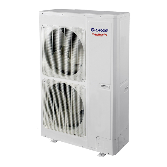
Ultra Heating GMV5 Multi VRF for North America PRODUCT 1 PRODUCT LIST 1.1 Outdoor Unit Cooling Capacity Heating Capacity Product Power Model Refrigerant Appearance Code Supply Kw(Btu/h) Kw(Btu/h) 10.5 13.2 GMV-36WL/B-T(U) CN850W0380 (36000) (45000) 208/230V R410A 60Hz 14.1 15.8 GMV-48WL/B-T(U) CN850W0360 (48000) (54000) -
Page 5: Nomenclature
□ □ □ □ □ Description Options Product code GMV-Gree Multi VRF Units Blank-T1 condition; T2-low temperature climate; Suitable climate T3-high temperature climate Unit type DC Inverter (omit) Q—Heat Recovery; S—Water Heater; W—Water-cooled Unit; X—Fresh Air Unit Function code Leave blank if above functions are unavailable. -
Page 6: Product Features
3 PRODUCT FEATURES 3.1 General introduction Gree Multi VRF System adopts inverter compressor technology. By changing the displacement of compressor, stepless capacity regulation within range of 15%~100% can be realized. Various product lineups are provided with capacity range from 36000Btu/h to 48000Btu/h, which can be widely used in residential, commercial and working area and especially applicable to places with big load change. -
Page 7: Specifications
Ultra Heating GMV5 Multi VRF for North America Filter can be cleaned ◆ Quiet design ◆ One IDU with several wired controller and several IDUs with one wired controller ◆ One IDU can be connected with several wired controllers in order to control one IDU from different location; meanwhile, several IDUs can be connected with one wired controller in order to achieve centralized control of 16 IDUs in maximum. - Page 8 Ultra Heating GMV5 Multi VRF for North America 4.2 Indoor Unit 4.2.1 Low Static Pressure Duct Type IDU GMV- GMV- GMV- GMV- GMV- GMV- Model ND07PLS/ ND09PLS/ ND12PLS/ ND14PLS/ ND18PLS/ ND22PLS/ A-T(U) A-T(U) A-T(U) A-T(U) A-T(U) A-T(U) Product Code CM810N0080 CM810N0090 CM810N0100 CM810N0120 CM810N0070 CM810N0110 Btu/h 7500 9500...
- Page 9 Ultra Heating GMV5 Multi VRF for North America 4.2.2 4-way Cassette Type IDU GMV-ND07T/ GMV-ND09T/ GMV-ND12T/ GMV-ND15T/ GMV-ND18T/ Model A-T(U) A-T(U) A-T(U) A-T(U) A-T(U) Product Code CM500N0520 CM500N0530 CM500N0540 CM810N0130 CM500N0510 Btu/h 7500 9500 12000 15000 18000 Cooling Capacity Btu/h 8500 10500 13500...
- Page 10 Ultra Heating GMV5 Multi VRF for North America GMV-ND24T/ GMV-ND30T/ GMV-ND36T/ GMV-ND42T/ GMV-ND48T/ Model A-T(U) A-T(U) A-T(U) A-T(U) A-T(U) Product code CM500N0550 CM500N0560 CM500N0570 CM500N0580 CM500N0590 Btu/h 24000 30000 36000 42000 48000 Cooling Capacity 10.6 12.3 14.1 Btu/h 27000 34000 40000 47000 54000...
- Page 11 Ultra Heating GMV5 Multi VRF for North America 4.2.3 Features of Wall Mounted GMV-N07G/A3A- GMV-N09G/A3A- GMV-N12G/A3A- GMV-N18G/A3A- GMV-N24G/A3A- Model D(U) D(U) D(U) D(U) D(U) Product code CM100N1480 CM100N1490 CM100N1500 CM100N1510 CM100N1520 Btu/h 7500 9500 12000 18000 24000 Cooling Capacity Btu/h 8500 11000 13500...
-
Page 12: Capacity Code
Ultra Heating GMV5 Multi VRF for North America 5.2 Capacity Code Instruction of capacity code: GMV-36WL/B-(U) and GMV-48WL/B-(U) are identical in components, systems and structure, etc. 5.3 Capacity Correction Formula5.1 Correction factor of indoor and outdoor temperature 5.3.1 Rated capacity of outdoor unit Model GMV-36WL/B-T(U) GMV-48WL/B-T(U) -
Page 13: Principal Of Operation
Ultra Heating GMV5 Multi VRF for North America cooling and 30 C(86 F) for heating). Hp(m) Hp(m) 20 30 40 50 70 80 90 10 01 1301 40 20 30 40 50 70 80 90 1001 1301 40 L(m) L(m) Hm(m) Hm(m) Variance ratio of heating capacity... - Page 14 Ultra Heating GMV5 Multi VRF for North America In cooling, the low-temperature and low-pressure refrigerant gas from each indoor heat exchanger will be merged and inhaled by the compressor and then become high-temperature and high-pressure gas, which will later be discharged into outdoor heat exchangers. By with indoor air, refrigerant wil become low-temperature and low-pressure gas again and repeat the circulation so as to realize the cooling effect.
-
Page 15: Control
Ultra Heating GMV5 Multi VRF for North America CONTROL CONTROL... -
Page 16: Units' Control
Ultra Heating GMV5 Multi VRF for North America CONTROL 1 Units’ Control 1.1 Schematic diagram of units’ control Air conditioning units can be divided into indoor unit and outdoor unit. A maximum of 16 sets of indoor units can be connected to an outdoor unit. 2-core (3-core pin header) communication cable is used for the connection between indoor unit and outdoor unit. -
Page 17: Wired Controller
Ultra Heating GMV5 Multi VRF for North America 2 Wired Controller 2.1 Control panel Fig. 1.1 Appearance of wired controller Fig. 1.2 LCD graphics of wired controller LCD Display Instruction Table 1.1 LCD display instruction Symbols Instructions Up and down swing function Left and right swing function It's valid under Save mode and displays during setting process. - Page 18 Ultra Heating GMV5 Multi VRF for North America Cooling mode Dry mode Fan mode Heating mode When inquiring or setting project number of indoor unit, it displays "NO." icon Floor Heating mode (When Heating and Floor Heating simultaneously shows up, it indicates 3D Heating is activated.) Display "SET"...
- Page 19 Ultra Heating GMV5 Multi VRF for North America Button Graphics Fig. 1.3 Button graphics 2.2 Installation and removal 2.2.1 Installation dimensions Unit:mm 42.5 Unit:mm Fig.2.1.1 Dimension of wired controller 42.5 82.5 inch 4.41 0.87 0.11 0.13 0.20 1.67 1.57 3.25 2.2.2 Installation method H1 H 2 H1 H 2...
- Page 20 Ultra Heating GMV5 Multi VRF for North America 2.2.3 Removal method Fig.2.1.3 Removal of Wired Controller 2.2.4 Connection of communication cord There are 4 ways to connect wired controller with indoor units’ network: Outdoor unit Outdoor unit Indoor unit Indoor unit Fig.
- Page 21 Ultra Heating GMV5 Multi VRF for North America Outdoor unit Indoor unit 16 Indoor unit 1 Indoor unit 2 Fig. 3.6 Two wired controllers control multiple indoor units simultaneously 2.3 Engineering Test 1)Mater IDU Settings In power-off status, press and hold the “MODE” button for five seconds to set the IDU connected with the current wired controller to master IDU.If the setting is successful, MASTER icon will be on.
- Page 22 Ultra Heating GMV5 Multi VRF for North America switch to the next IDU Indoor unit quantity Timer area: displays the number of IDUs in the system query in the system 1-80 network. network Operation method: In” C06” status,press “ MODE” button to enter Preferential 00:Common operation query interface.Press“...
- Page 23 Ultra Heating GMV5 Multi VRF for North America wired controller parameter setting interface.The temperature area displays “ P00” . (2) Select a parameter code by pressing“ ∧ ∧ ” or“ ∨ ∨ ” .Press the “ MODE” button to switch to parameter value setting.The parameter value blinks.Adjust the parameter value by pressing “...
- Page 24 Ultra Heating GMV5 Multi VRF for North America pressure levels according to the maximum control principle.If the static pressure lelvls received by the IDU from wired controller,remote controller,or remote monitoring system exceed the setting range,the limit value prevails. 3. During power-on and synchro- nization the setting value of static pressure leverls is determined by setting of the IDU.
- Page 25 Ultra Heating GMV5 Multi VRF for North America Press ON/OFF button again to turn off the unit. The interfaces of On/Off status are shown as follow: 2)Mode Setting Under On status, pressing MODE button can set mode circularly as: Note: ①There will be different mode with different model of the uint.The wired controller will select the range of setting mode according to the model of indoor unit ②...
- Page 26 Ultra Heating GMV5 Multi VRF for North America continuously press “ ∨ ∨ ” button twice to decrease temperature to 12°C (when Save function is activated, the temperature in Dry mode can’t be adjusted to 12°C and the setting range is “l owest temperature in Save mode”...
- Page 27 Ultra Heating GMV5 Multi VRF for North America b. Clock Setting Clock display: when the timer setting way is clock timer, timer zone displays system clock in unit On and Off status. icon is bright and the clock can be set at this time. Clock setting: long press TIMER button for 5s to enter clock setting and icon is blinking.
- Page 28 Ultra Heating GMV5 Multi VRF for North America “∧ ∧ ”or“∨ ∨ ” “∧ ∧ ”or“∨ ∨ ” Pressing button increases or decreases timer time by 1min; holding button for 5s increases or decreases timer time by 10min. Clock Timer setting is shown as follow: 6) Swing Setting In unit on status, up &...
- Page 29 Ultra Heating GMV5 Multi VRF for North America Up & down swing function has two modes: simple swing mode and fixed-angle swing mode. In unit off status, -angle press “SWING” button and ▲ button together for 5 seconds to switch between simple swing mode and fixed swing mode.
- Page 30 Ultra Heating GMV5 Multi VRF for North America 8) Sleep Setting Sleep Function: in this mode, the unit will operate according to the preset sleep curve to provide comfortable sleep environment. Turn on/off Sleep Function: in unit On status, press SLEEP button to tactivate or cancel Sleep function. When Sleep function is activated, icon is bright and quiet or auto quiet mode is also activated.
- Page 31 Ultra Heating GMV5 Multi VRF for North America is closed while quiet function is still activated; Under Auto,Fan or Floor Heating mode, this Sleep function is not available. 9) Air Setting Air Function: Adjust the amount of indoor fresh air to improve air quality and keep indoor air fresh. Turn on Air Function: When unit is on or off, press FUNCTION button and select Air.
- Page 32 Ultra Heating GMV5 Multi VRF for North America Note: When there is no button operation on the wired controller or no remote control signal is received for 20s continuously: ① If Light function is activated, the back light of LCD will turn to half bright. ②...
- Page 33 Ultra Heating GMV5 Multi VRF for North America Save Setting for Heating: When unit is on and under Heating, 3D Heating and Space Heating modes, press FUNCTION button to select Save function. ” or“ ” button to icon will blink and MAX icon lit up. Press “ ∧...
- Page 34 Ultra Heating GMV5 Multi VRF for North America The setting of Filter Clean Reminder function is shown as follow: Note: Description on cleaning level: When setting the Filter Clean Reminder Function, timer zone will display 2 digits, of which the former indicates the pollution degree of operating plac e and the latter indicates the operating time of indoor unit.
- Page 35 Ultra Heating GMV5 Multi VRF for North America The former digit shows 3 while the latter one shows 0, which indicates the accumulating Heavy operating time is 100 hours. Each time the latter digit increases 1, the operating time increases Pollution 100 hours.
-
Page 36: Remote Controller
Ultra Heating GMV5 Multi VRF for North America When there is Gate-control System, user can insert a card to turn on the unit or pull off a card to turn off the unit. When the card is re-inserted, the unit will recover the operation as state in memory. When the card is pulled off (or improperly inserted), icon will show. - Page 37 Ultra Heating GMV5 Multi VRF for North America 1) Button name and function introduction (outside) Button name Function ON/OFF Turn on or turn off the unit Set fan speed ▲/▼ Set temperature and time COOL Set cooling function HEAT Set heating function SWING Set swing status TURBO...
-
Page 38: Installation
Ultra Heating GMV5 Multi VRF for North America INSTALLATION... -
Page 39: Engineering Installation Preparation And Notice
Ultra Heating GMV5 Multi VRF for North America INSTALLATION 1 Engineering Installation Preparation and Notice 1.1 Installation notice Personnel and property safety are highly concerned during the entire installation process. Installation implementation must abide by relevant national safety regulations to ensure personnel and property safety. All personnel involved in the installation must attend safety education courses and pass corresponding safety examinations before installation. - Page 40 Ultra Heating GMV5 Multi VRF for North America The refrigerant pipe or condensate Water can easily condensate and drip to damage the indoor decoration, or even water pipe does not meet the insulation trigger the protection mode of system due to overheating operation. requirement.
-
Page 41: Installation Of Outdoor Unit
Ultra Heating GMV5 Multi VRF for North America NOTICE!: For air conditioning units installed in places with strong electromagnetic interference, shielded wire must be used as the communication cables of the IDU and wired controller, and shielded twisted pairs must be used as the communication cables between IDUs and between the IDU and ODU. -
Page 42: Installation Of Indoor Unit
Ultra Heating GMV5 Multi VRF for North America The outdoor unit will not be embedded by the snow and not affected by garbage and oil smog; ◆ The installation of outdoor unit shall adopt rubber damping pad or spring damper to reduce noise and vibration; ◆... - Page 43 Ultra Heating GMV5 Multi VRF for North America 4.1.1 Low Static Pressure Duct Type Unit The following diagram is applicable for units with the cooling capacity ranging from 7 k Btu/h to 22 k Btu/h. Liquid pipe Gas pipe Electric box Drain pipe The following table lists the detailed dimensions.
- Page 44 Ultra Heating GMV5 Multi VRF for North America All electrical installation must be done by professionals according to national and local laws and regulations. The unit must be grounded reliably. Please connect wire according to the wiring diagram on the unit. 4.2 Four-way Cassette Indoor Unit 4.2.1Requirements for external dimensions and installation and maintenance spaces Refrigerant...
-
Page 45: Installation Of Electronic Expansion Valve Assy (Unit With External Exv)
Ultra Heating GMV5 Multi VRF for North America 4.3 Installation of wall-mounted indoor unit 4.3.1 Outline and installation dimension Unit: mm(inch) Model GMV-N07G/A3A-D(U) 843(33-1/5) 275(10-5/6) 180(7) GMV-N09G/A3A-D(U) GMV-N12G/A3A-D(U) 940(37) 298(11-3/4) 200(7-7/8) GMV-N18G/A3A-D(U) GMV-N24G/A3A-D(U) 1008(39-2/3) 221(8-5/7) 319(12-5/9) 4.3.2 Installation space 天花板 天花板... -
Page 46: Installation Of Refrigerant Pipeline
Ultra Heating GMV5 Multi VRF for North America 6 Installation of Refrigerant Pipeline 6.1Allowable Length and Height Difference of Connection Pipe NOTICE! Equivalent length of one Y-type branch is 0.5m(1-5/8feet). The 1 branch section Piping parameters of GMV-36WL/B-T(U) 、GMV-48WL/B-T(U): Allowable value(m/feet) Fitting pipe 300(984) L1+L2+L3+a+b+c+d... - Page 47 Ultra Heating GMV5 Multi VRF for North America The 1 indoor branch Pipe between ODU and the 1 indoor branch Dimension of outdoor connection pipe: Pipe dimension Basic module Connection method Gas pipe (mm/inch) Liquid pipe(mm/inch) GMV-36WL/B-T(U) Φ15.9(5/8) Φ9.52(3/8) Flared joint GMV-48WL/B-T(U) Φ15.9(5/8) Φ9.52(3/8)
- Page 48 Ultra Heating GMV5 Multi VRF for North America Pipe between indoor branches Total capacity of downstream indoor units C (Btu/h) Gas pipe(mm/inch) Liquid pipe(mm/inch) C ≤ 19000 Φ12.7(1/2) Φ6.35(1/4) 19000 < C ≤ 48500 Φ15.9(5/8) Φ9.52(3/8) 48500 < C ≤ 75000 Φ19.05(3/4) Φ9.52(3/8) 6.5 Dimension of Pipe between Indoor Branch and IDU...
-
Page 49: Installation Of The Connection Pipe
Ultra Heating GMV5 Multi VRF for North America 7 Installation of the Connection Pipe 1) Conform to the following principles during pipe connection: Connection pipe should be as short as possible, so is the height difference between indoor and outdoor units. Keep the number of bends as little as possible. - Page 50 Ultra Heating GMV5 Multi VRF for North America 2) Connection pipe should be supported by a bearer rather than the unit. 3) The bending angle of piping should not be too small; otherwise the piping might have cracks. Please use a pipe bender to bend the pipe.
- Page 51 Ultra Heating GMV5 Multi VRF for North America 2) Y-type branch has several pipe sections with different dimension, which facilitates to match with various copper pipes. Use pipe cutter to cut in the middle of the pipe section that is of proper dimension and remove burrs as well. 3) Y-type branch must be installed vertically or horizontally.
- Page 52 Ultra Heating GMV5 Multi VRF for North America 1) Thermal insulating material shall be able bear the pipe temperature. For heat pump unit, liquid pipe should bear 70 C(158 F) or above and gas pipe should bear 120 C(248 F) or above. For cooling only unit, both liquid pipe and gas pipe should bear 70 C(158 F) or above.
- Page 53 Ultra Heating GMV5 Multi VRF for North America Manometer Manometer HI knob LO knob Liquid valve Vacuum pump Connection hose Gas valve 7.3.2 Refrigerant Adding (1) Refrigerant quantity of outdoor unit before delivery: Mode GMV-36WL/B-T(U) GMV-48WL/B-T(U) Refrigerant Qty (kg/oz) 6.5(229) 6.5(229) 1) The refrigerant amount charged before delivery doesn’t include the amount that needs to be added to indoor units and the connection pipeline.
-
Page 54: Installation Of Condensate Pipes
Ultra Heating GMV5 Multi VRF for North America Indoor Indoor Indoor Indoor Indoor ① ② ③ ④ Duct type Duct type Duct type Duct type Model GMV-ND18PLS/A-T(U) GMV-ND12PLS/A-T(U) GMV-ND09PLS/A-T(U) GMV-ND09PLS/A-T(U) Liquid pipe: Pipe size Φ9.52mm(3/8inch) Φ9.52 mm(3/8inch) Φ9.52 mm(3/8inch) Φ6.35 mm(1/4inch) Length 10m(32-3/4feet) 5m(16-3/8feet) - Page 55 Ultra Heating GMV5 Multi VRF for North America Indoor unit Install a drain trap connector for each unit. The drain trap connector shall be installed in a way that facilitates trap cleaning. Connector Indoor unit Indoor unit Connector 8.1.5 During condensate water pipe installation, ensure a distance above 500 mm between the pipe and the electric box of the unit for 8.2.
-
Page 56: Electric Wiring
Ultra Heating GMV5 Multi VRF for North America Insulation layer for the condensate water pipe Pipe cover 8.2.2 Drain Pipe Installation for IDU a. Use pipe clips instead of applying glue to connect the hoses provided upon delivery and plastic pipes on the device. Connect the other end of the joint to the elbow. - Page 57 Ultra Heating GMV5 Multi VRF for North America 5) Connect the unit to specialized grounding device and make sure it is securely grounded. It’s a must to install air switch and current circuit breaker that can cut off the power of the entire system. The air switch should include magnetic trip function and thermal trip function so that system can be protected from short circuit and overload.
-
Page 58: Debugging Of Unit
Ultra Heating GMV5 Multi VRF for North America 9.2 Power Cable Wire Gauge and Circuit Breaker Selection 9.2.1 Outdoor Max Fuse Size/ Max Ckt, Bkr Size/ Model Power supply Fusible Max. Min. Circuit Ampacity Disjoncteur Max.(A) GMV-36WL/B-T(U) 208/230V~ 60Hz GMV-48WL/B-T(U) 208/230V~ 60Hz 9.3.2 Indoor (1) Low Static Pressure Duct Type Indoor Unit... - Page 59 Ultra Heating GMV5 Multi VRF for North America 10.2.1 Notice (1) Before the test running, make sure the unit is power on and compressor has been preheated o l l s ’ t y l l Start test operation after unit is normally preheated, otherwise compressor might be damaged. Outdoor Temperature/℃...
- Page 60 Ultra Heating GMV5 Multi VRF for North America Before test operation The appearance of the unit and the refrigerant pipes cannot be damaged during the installation. Do not switch on power before installation is finished completely. Electrical wiring must be connected correctly and securely. ...
- Page 61 Ultra Heating GMV5 Multi VRF for North America Running The display of function section The display of data section state ① If the function section displays the ① The section will display the numbers of the indoor units, the data numbers of the indoor units which have section will...
- Page 62 Ultra Heating GMV5 Multi VRF for North America Initial state Long press “Fuc” key for more than 2s Switch with “Fuc” Press “Enter” Press “Enter” Press “Enter” OF/ON Setting is done Press “Enter” Press “Enter” Switch with Hi/nor/Lo Setting is done “Fuc”...
- Page 63 Ultra Heating GMV5 Multi VRF for North America Set parameters: Press “Enter” key to enter the second-level menu, and set parameters with the “+” “-” keys. Now the function section displays the running code uninterrupted and the data section flashes the set parameters.
- Page 64 Ultra Heating GMV5 Multi VRF for North America The meaning of running code: Function Sorts Data section Remarks section Control Unit Blank Use the “+” “-” keys to switch L, N Set evaporation and H. Default:N temperature If you want to get a higher cooling capacity, select L;...
- Page 65 Ultra Heating GMV5 Multi VRF for North America 10.4 Parameters reference value for the normal operation of unit Parameters name Unit Reference value Outdoor ℃ ― temperature After compressor is started up, normal discharge temperature for cooling is 60~105℃ , which is 10℃...
-
Page 66: Maintenance
Ultra Heating GMV5 Multi VRF for North America MAINTENANCE... -
Page 67: Malfunction List
Ultra Heating GMV5 Multi VRF for North America DEBUGGING & MAINTENANCE 1 Malfunction List 1.1 Error Code of Protection Indoor Unit Outdoor Unit Error Item Code Display Display Indoor fan protection Water overflow protection Anti-freeze protection Mode conflict Indoor ambient temperature sensor error Indoor coil inlet temperature sensor error Indoor mid-coil temperature sensor error Indoor coil outlet temperature sensor error... - Page 68 Ultra Heating GMV5 Multi VRF for North America IPM module overheat Desynchronizing protection Busbar over voltage protection Phase current detection fault Busbar under voltage protection Capacitor charge error Demagnetization protection Communication error between indoor and outdoor units, indoor unit’s wired controller 485 communication error between main controller and drive controller Fan motor error...
-
Page 69: Troubleshooting
Ultra Heating GMV5 Multi VRF for North America 1.3 Operation Code Operation Code Indoor Unit Display Outdoor Unit Display Trail run Fluorine recycle Defrosting Oil return Testing online Vacuumization Test module Note: Last ten records of protection shutdown or limited frequency reduction for protection can be searched through the debugging controller. - Page 70 Ultra Heating GMV5 Multi VRF for North America (2) Low-pressure protection Low pressure protecti o n Me asure wh ethe r the low Me asure wh ether the R e place ma in b oa rd o f pressure i s t oo low with pressure s witc h is ou tdoor u nit ma...
- Page 71 Ultra Heating GMV5 Multi VRF for North America (3) Discharge temperature protection...
- Page 72 Ultra Heating GMV5 Multi VRF for North America (4) Mafunction of temperature sensor (5) Malfunction of sensor (6) Unit and main board can’t be energized...
-
Page 73: Power Distribution Of Unit
Ultra Heating GMV5 Multi VRF for North America (7) Failure start-up 3 Power Distribution of Unit 3.1 Power distribution of unit The main loop is showed by bold line (line width: 1mm); the control loop is showed by slim line (line width: 0.2mm). Power wiring board Filter plate Drive board... - Page 74 Ultra Heating GMV5 Multi VRF for North America 3.3Circuit diagram Note: This drawing is just for reference; please always refer to the electric wiring stuck to the unit for actual wiring. 3.3.1Circuit diagram of outdoor unit YEGN POWER AC-L W12 RD W11 YE W8 YEGN DRIVE BOARD...
- Page 75 Ultra Heating GMV5 Multi VRF for North America 3.3.2 Circuit Diagram (1) Low Static Pressure Duct Type IDU GMV-ND07PLS/A-T(U) ~ GMV-ND22PLS/A-T(U): Envir onment IN D O O R U N I T O u t I n XT...
-
Page 76: Removal Of Parts
Ultra Heating GMV5 Multi VRF for North America (3) Wall Mounted Type IDU GMV-N07G/A3A-D(U)~GMV-N24G/A3A-D(U): RECE I V ER A N D Electroni c e xpansion v alve D I SPLAY BO AR D IN D O O R U N I T ... - Page 77 Ultra Heating GMV5 Multi VRF for North America It stays between discharge outlet of compressor and inlet of condenser. It used for separating the lubricant Oil separator oil of compressor when the high temperature and high pressure refrigerant gas is discharged from the compressor.
- Page 78 Ultra Heating GMV5 Multi VRF for North America 2. Remove front side screwdriver plate sub- ● Hold the front side plate upwards and then put it assy 3. Remove front panel with screwdriver and grille 4. Remove left side plate with screwdriver plate and ●...
- Page 79 Ultra Heating GMV5 Multi VRF for North America 2. Remove blade 3. Remove ● then remove the power cord of motor motor ● Take out the damaged motor ● Replace the motor, tighten screws with screwdriver and then connect teh power cord of 4.
- Page 80 Ultra Heating GMV5 Multi VRF for North America screwdriver 1. Remove ● Then pull out the power cord wiring cover of Note: When removing the power cord, make marks compressor for different color power cords and corresponding wiring terminals for wrong terminal. ●...
- Page 81 Ultra Heating GMV5 Multi VRF for North America 7. Connect the screwdriver power cord of ● conenct the power cord well again compressor well Note: When connecting the power cord, make marks for different color power cords and corresponding wiring terminals. ●...
- Page 82 Ultra Heating GMV5 Multi VRF for North America ● Replace 4-way valve 3. Replace Note: During welding process, do not 4-way valve ● Weld the connection position 4. Replace between 4-way valve and pipeline 4-way valve Note: During welding process, do not Remival operation for eletronic expansion valve Remark: Before removing the electronic expansion valve, please make sure that there’s no refrigerant in th pipeline of system and the power is disconnected...
- Page 83 Ultra Heating GMV5 Multi VRF for North America ● Weld the connection pipe of electronic expansion valve 3. Replace ● Inistall the coil of electronic electronic expansion valve expansion valve Note: During welding process, do Removal operation of gas liquid separator Remark: Before removing the gas liquid separator, please make sure that there’s no refrigerant inside the pipeline of system and disconnect the power Process...
- Page 84 Ultra Heating GMV5 Multi VRF for North America 4.3 Assembling and Disassembling Key Parts of IDUs6 Common Maintenance ◆ Low static pressure duct similar except the numbers of louvers and motors. Motor and fan Precondition: The power supply has been disconnected. Step Diagram Operation Procedure...
- Page 85 Ultra Heating GMV5 Multi VRF for North America ◆ Four-way Cassette Motor and fan Step Diagram Operation Procedure Loosen the screws 1. Unscrew the ●Use a screwdriver to unscrew the water tray. water tray. 2. Remove the ●Remove the water tray. water tray.
- Page 86 Ultra Heating GMV5 Multi VRF for North America 7. Screw the ●Use a screwdriver to screw the motor. motor. 8. Install and ●Install the louver and use a wrench screw the louver. to screw the louver. Loosen the screws 9. Install and ●Use a screwdriver to screw the screw the water water tray...
- Page 87 DC Inverter Side Discharge VRF Ⅱ for North America 4. Replace the pump. ●Replace the pump. 1. Screw the outlet pipe 2. Screw the pump 5. Connect the drainage duct ●Connect the drainage duct and use a and screw the new pump. screwdriver to screw the new pump.
- Page 88 Ultra Heating GMV5 Multi VRF for North America 4. Remove the front panel panel assembly. assembly ●Remove the front panel assembly. 5. Remove the electrical box ●Press on the buckle of the box cover 1 cover 1 and then take off the cover. ●Release the wiring terminals connected 6.
-
Page 89: Vacuum Drying For The System
Ultra Heating GMV5 Multi VRF for North America 5 Vacuum drying for the system 5.1 Selection requirement for the vaccum pump Do not use different vacuum pump for vaccum-pumping for different refrigerant system ; The final vacuum for the vacuum pump should reach -0.1MPa. The air discharge volume for the vacuum pump should reach 4L/S above;... - Page 90 Ultra Heating GMV5 Multi VRF for North America NOTICE (1) The refrigerant amount charged before delivery doesn’t include the amount that needs to be added to indoor units and the connection pipeline. (2) Length of connection pipe is decided on site. Therefore the amount of additional refrigerant shall be decided on site according to the dimension and length of field-installed liquid pipe.
- Page 91 Ultra Heating GMV5 Multi VRF for North America NOTICE! Liquid pipe that is within 20m (65-5/8 feet) doesn’t need to be added refrigerant. Therefore, the minimum quantity of additional refrigerant = (23-20)×0.054+11×0.022= 0.404kg(14oz). 5.3.2 Operation procedure for adding refrigerant (1) Put the charging tank on the weightometer, record the reading and then calculate the data after charging refrigerant;...
-
Page 92: Exploded View Of Unit And Parts' List
Ultra Heating GMV5 Multi VRF for North America Step 1: Increase pressure slowly to 0.5MPa, stop for 5min and then check the gas leakage. Big leakage may be found out; Step 2: Increase pressure slowly to 1.5MPa, stop for 5min to check the airtightness. Small leakage may be found out;... - Page 93 Ultra Heating GMV5 Multi VRF for North America Parts list: GMV-36WL/B-T(U)\GMV-48WL/B-T(U) Name of Part Product Code CN850W0380\CN850W0360 Part Code Quantity Coping 01264100008P Electric Box Cover 012020000071 Motor Support Sub-Assy 017012000032 Brushless DC Motor 15704100013 Brushless DC Motor 1570410001301 PFC Inductance 340032000005 Cable Cross Loop 76512008...
- Page 94 DC Inverter Side Discharge VRF Ⅱ for North America 07330000002 Liquid side stop Valve Underlay groupware 01894100090 Electrical Heater(compressure) 7651521215 Magnet Coil 4304000425 Electromagnetic Valve 43000054 Electromagnetic Valve groupware 43044100234 Electromagnetic Valve groupware 43044100232 Electromagnetic Valve 43003091 Magnet Coil 4304000439 Chassis Sub-assy 01194100051P Drainage Connecter...
- Page 95 JF00302969...