Table of Contents
Advertisement
Quick Links
Installation & Owner's Manual
Original Instructions
Air Conditioners
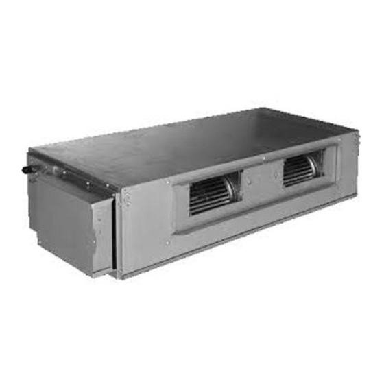
DC Inverter U-match Series Duct Type Unit
Models:
Indoor Unit
UMAT18HP230V1BD
UMAT24HP230V1BD
UMAT30HP230V1BD
UMAT36HP230V1BD
UMAT42HP230V1BD
UMAT48HP230V1BD
Outdoor Unit
UMAT18HP230V1BO
UMAT24HP230V1BO
UMAT30HP230V1BO
UMAT36HP230V1BO
UMAT42HP230V1BO
UMAT48HP230V1BO
Advertisement
Table of Contents

Related Manuals for Gree UMAT18HP230V1BD


Summary of Contents for Gree UMAT18HP230V1BD
- Page 1 Installation & Owner's Manual Original Instructions Air Conditioners DC Inverter U-match Series Duct Type Unit Models: Indoor Unit Outdoor Unit UMAT18HP230V1BD UMAT18HP230V1BO UMAT24HP230V1BD UMAT24HP230V1BO UMAT30HP230V1BD UMAT30HP230V1BO UMAT36HP230V1BD UMAT36HP230V1BO UMAT42HP230V1BD UMAT42HP230V1BO UMAT48HP230V1BD UMAT48HP230V1BO...
- Page 2 To Users Thank you for selecting Gree’s product. Read this instruction manual carefully before installing and using the product. For correct installation and use of our product and in order to achieve its expected operation, follow the instuctions provided below:...
- Page 3 (7) The final right to interpret for this instruction manual belongs to Gree Electric Appliances Inc. of Zhuhai. Exception Clauses The Manufacturer bears no responsibilities when personal injury or property loss is caused by the following reasons: (1) Damage to the product due to improper use or misuse of the product;...
-
Page 4: Table Of Contents
Contents 1 Safety Precautions ............... 1 2 Outline of the Unit and Main Parts ........2 3 Preparative for Installation ........... 3 3.1 Standard Accessory Parts ............3 3.2 Selection of the Installation Location ........4 3.3 Connection Pipe Requirement ..........6 3.4 Electrical Requirement ............. -
Page 5: Safety Precautions
DC Inverter U-match Series Duct Type Unit 1 Safety Precautions This is the safety alert symbol. It is used to alert you to potential personal injury hazards. Obey all safety messages that follow this symbol to avoid possible injury or death. This mark indicates procedures which, if improperly performed, might lead to the death or serious injury of the user. -
Page 6: Outline Of The Unit And Main Parts
DC Inverter U-match Series Duct Type Unit (13) Children should be supervised to ensure that they do not play with the appliance. (14) If the power supply wiring is damaged, it must be replaced by a licensed technician or similarly qualified persons, in order to avoid a hazard. 2 Outline of the Unit and Main Parts* *Not all items are included with... -
Page 7: Preparative For Installation
DC Inverter U-match Series Duct Type Unit ① The pipe connections , drain pipe, power upply wire, and duct for this unit should be prepared by the installer. ② The unit is designed for rectangular duct connections. 3 Preparing for Installation 3.1 Standard Accessory Parts The standard accessory parts listed below are furnished and should be used as required. -
Page 8: Selection Of The Installation Location
DC Inverter U-match Series Duct Type Unit Indoor Unit Accessories Name Appearance Q'ty Usage To connect liquid pipe To connect gas pipe Table 3.2 Outdoor Unit Accessories Name Appearance Q'ty Usage 1 or To plug the unused Drain Plug drain hole To connect with the Drainage Connecter hard PVC drain pipe... - Page 9 DC Inverter U-match Series Duct Type Unit Fig. 3.1 (4) Install the unit where the drain pipe can be easily installed. (5) Provide as much space as possible from the unit to the ceiling to enable convenient servicing. 3.2.2 Outdoor Unit ①...
-
Page 10: Connection Pipe Requirement
(inch) Item Pipe between Diameter × Model Length Indoor Unit wall Liquid m (feet) and Outdoor thickness) Unit m (feet) mm (inch) Φ20X1.2 UMAT18HP230V1BD (Φ0.79×0.05) 6(1/4) 12(1/2) 50(164.0) 15(49.2) UMAT18HP230V1BO Φ26X3 (Φ1.02×0.12) Φ20X1.2 (Φ0.79×0.05) UMAT24HP230V1BD 9.52(3/8) 16(5/8) 50(164.0) 15(49.2) UMAT24HP230V1BO Φ26X3... -
Page 11: Electrical Requirement
3.4 Electrical Requirement Electric Wire Size and Fuse Capacity. Table 3.4 Maximum Minimum Circuit Power Supply Fuse Capacity Overcurrent Ampacity Indoor Units Protection V/Ph/Hz UMAT18HP230V1BD 208V/230V~60Hz UMAT24HP230V1BD 208V/230V~60Hz UMAT30HP230V1BD 208V/230V~60Hz UMAT36HP230V1BD 208V/230V~60Hz UMAT42HP230V1BD 208V/230V~60Hz UMAT48HP230V1BD 208V/230V~60Hz Table 3.5 Maximum... -
Page 12: Installation Of The Unit
DC Inverter U-match Series Duct Type Unit must be positioned so that the wiring connections are accessible. ③ Take 2 wires of the power wire of 0.75mm2 (AWG18) as the communication lines between indoor and outdoor unit, with their longest lengths of 70m (230feet). - Page 13 DC Inverter U-match Series Duct Type Unit For the units: 18k~30k For the units: 36k~42k...
- Page 14 DC Inverter U-match Series Duct Type Unit For the units: 48k Fig. 4.1 Table 4.1 Unit: mm (inch) Item Model 1100 1160 1280 1000 UMAT18HP230V1BD (43-3/8) (20-3/8) (32-1/4) (45-5/8) (50-3/8) (22) (39-1/2) (6-1/4) (9-1/4) (10-1/2) UMAT24HP230V1BD 1010 1115 1225 (39-3/4)
- Page 15 DC Inverter U-match Series Duct Type Unit (3) Install the hanger to the unit (Fig. 4.5). (4) Pass the unit hangers over the bolts installed to the ceiling and install the unit with the special nut (Fig. 4.6). φ 12.7mm(1/2inch) Fig.4.2 Fig.4.3 Fig.4.4...
-
Page 16: Installation Of The Outdoor Unit
DC Inverter U-match Series Duct Type Unit Fig. 4.7 4.2 Installation of the Outdoor Unit ① Install the unit where it will not be tilted by more than 5°. ② During installation, if the outdoor unit has to be exposed to strong wind, it must be fixed securely. 4.2.1 Outdoor unit dimension Fig. -
Page 17: Installation Of The Connection Pipe
DC Inverter U-match Series Duct Type Unit 4.2.2 Condensate Drainage of the Outdoor Unit (Only for the heat pump unit) (Fig. 4.9) (1) It is required to install a drain pipe for the outdoor unit to drain out the condensate water during heating operation (only for the heat pump unit). (2) When installing the drain pipe, apart from the drain pipe mounting hole, all other holes should be plugged so as to avoid water leakage (only for the heat pump unit). - Page 18 DC Inverter U-match Series Duct Type Unit 4.3.2 Bending Pipes (1) The pipes are shaped by your hands. Be careful not to collapse them. Fig. 4.11 (2) Do not bend the pipes in an angle more than 90°. (3) When pipes are repeatedly bent or stretched, the material will harden, making it difficult to bend or stretch them any more.
- Page 19 DC Inverter U-match Series Duct Type Unit Centering the pipe against port on the indoor unit turn the flare nut with your hand. Hold the torque wrench at its grip, keeping it in the right angle with the pipe as shown in Fig. 4.13, in order to tighten the flare nut correctly.
- Page 20 DC Inverter U-match Series Duct Type Unit 4.3.4 Connecting the Pipe at the Outdoor Side Unit Tighten the flare nut of the refrigerant pipe at the outdoor unit valve connector. The tightening method is the same as that as at the indoor side. Fig.
-
Page 21: Vacuum And Gas Leakage Inspection
DC Inverter U-match Series Duct Type Unit 4.3.7 Liquid Pipe and Drain Pipe (1) If the outdoor unit is installed lower than the indoor unit (See Fig. 4.17) 1) A drain pipe should be above ground and the end of the pipe does not dip into water. - Page 22 DC Inverter U-match Series Duct Type Unit of the manifold valve assembly should be kept closed, otherwise evacuation would fail. (5) The evacuation duration depends on the unit’s capacity, generally, 20 minutes for the 18k units, 30 minutes for the 24k/30k/36k units, 45 minutes for the 42k/48k units.
-
Page 23: Installation Of The Drain Hose
DC Inverter U-match Series Duct Type Unit 4.4.2 Additional Charge Refrigerant suitable for a piping length of 7.6m (25feet) is charged in the outdoor unit at the factory. When the piping is longer than 7.6m (25feet), additional charging is necessary. For the additional amount, see Table 4.4. - Page 24 DC Inverter U-match Series Duct Type Unit 4.5.1 Installation of Drain Piping Install the drain hose in accordance with the instructions in this installation manual and keep the area warm enough to prevent condensation. Problems with the piping may lead to water leaks. (1) Install the drain hose with downward gradient (1/50 to 1/100) and no risers or traps are used for the hose (Fig.
- Page 25 DC Inverter U-match Series Duct Type Unit Fig. 4.24 (5) Use a suitable drain hose, and see Table 3.3 for its size. (6) There is a drain port on both the left and right sides. Select the drain port to match the local conditions (Fig.
- Page 26 DC Inverter U-match Series Duct Type Unit Fig. 4.26 Fig. 4.27 (11) There is adhesive on one side of the insulation so that after removing the protective paper over it the insulation can be directly attached to the drain hose. Considerations for the unit with the condensate pump: 1) For the unit with the condensate pump, only one drain port at the side close to the electric box is prepared and only through it the drain hose can...
- Page 27 DC Inverter U-match Series Duct Type Unit The vertical height of the drain hose should be 75mm (3inch) or less so that it is unnecessary for the drain port to withstand additional force. Fig. 4.29 When multiple drain hoses are used, their installation should be performed as shown in the figure below.
-
Page 28: Installation Of The Duct
Fig. 4.32 Supply Air Outlet Fig. 4.33 Return Air Inlet Table 4.5 Unit: mm (inch) Item Supply Air Outlet Return Air Inlet Model 158(6-1/4) 818(32-1/4) 994(39-1/8) 195(7-5/8) UMAT18HP230V1BD 160(6-1/4) 820(32-1/4) 980(38-5/8) 230(9) UMAT24HP230V1BD UMAT30HP230V1BD 160(6-1/4) 820(32-1/4) 980(38-5/8) 230(9) UMAT36HP230V1BD 195(7-5/8) - Page 29 DC Inverter U-match Series Duct Type Unit 4.6.2 Installation of the Supply Air Duct (1) Installation of the Rectangular Duct. Fig. 4.34 Table 4.6 Installation of the rectangular duct Name Name Hanger Filter Air Intake Pipe Main Air Supply Pipe Canvas Air Pipe Air Supply Outlet Air Intake...
- Page 30 DC Inverter U-match Series Duct Type Unit (3) If the bottom return air is desired, just change the place of the rectangular flange and the return air cover plate. (4) Connect one end of the return air duct to the return air outlet of the unit by rivets and the other to the return air louver.
-
Page 31: Electrical Wiring
DC Inverter U-match Series Duct Type Unit 4.7 Electrical Wiring 4.7.1 Wiring Precautions ① Before obtaining access to terminals, all supply circuits must be disconnected. ② The rated voltage of the unit is as shown as Table 3.4 and Table 3.5. ③... - Page 32 DC Inverter U-match Series Duct Type Unit 3) Using a round terminal fastener or pliers, securely clamp a round terminal to each stripped wire end. 4) Position the round terminal wire, and replace and tighten the terminal screw with a screwdriver (Fig. 4.38). Fig.
- Page 33 DC Inverter U-match Series Duct Type Unit (4) Electric wiring between the indoor and outdoor units Single-phase units (18k-30k) Single-phase units (36k-48k) Fig. 4.40 (5) Electric wiring of indoor unit side Remove the electric box cover from the electric box sub-assy and then connect the wire.
- Page 34 DC Inverter U-match Series Duct Type Unit ① The power wire and the wire of the fresh air valve are high-voltage, while the communication wire and connection wire of the wired controller are low-voltage. They should run separately to avoid electromagnetic interference. ②...
-
Page 35: Installation Of Controllers
DC Inverter U-match Series Duct Type Unit 5 Installation of Controllers Refer to the Installation Manual of the controller for more details. 6 Test Running 6.1 Trial Operation and Testing (1) The meaning of error codes as shown below: Table 6.1 Number Error code Error... - Page 36 DC Inverter U-match Series Duct Type Unit Number Error code Error Remarks Compressor phase sequence protection Compressor stalling protection Power protection Indoor and outdoor mismatch 4-way valve direction changing protection Drive reset protection Over-current protection Communication error between main control and drive Drive module sensor error Drive module over temperature protection Zero passage protection...
-
Page 37: Working Temperature Range
DC Inverter U-match Series Duct Type Unit 6.2 Working Temperature Range Table 6.2 Indoor Side Outdoor Side Test Condition DB(°C/°F) WB(°C/°F) DB(°C/°F) WB(°C/°F) Nominal Cooling 26.7(80.0) 19.4(67.0) 35.0(95.0) 23.9(75.0) Nominal Heating 21.1(70.0) 15.6(60.0) 8.33(47.0) 6.11(43.0) Rated Cooling 26.7(80.0) 19.4(67.0) 46.1(115.0) 23.9(75.0) Low Temp. -
Page 38: Unit Function
DC Inverter U-match Series Duct Type Unit 7 Unit Function 7.1 Setting of Double Indoor Room Sensors This series of ducted air-conditioning units has two indoor room sensors. One is located at the air intake of the indoor unit and the other one is located inside the wired controller. -
Page 39: Fresh Air Control
DC Inverter U-match Series Duct Type Unit 7.3 Fresh Air Control 11-levels control can be realized for the amount of fresh air taken in. The function not only facilitates the health of users, but also controls the electricity consumption loss because of taking in fresh air. This kind of control can be carried out through the wired controller. -
Page 40: Troubleshooting And Maintenance
DC Inverter U-match Series Duct Type Unit 8 Troubleshooting and Maintenance 8.1 Troubleshooting If your air-conditioning unit suffers from abnormal operation or failure, first check the following points before repair: Failure Possible Reasons ① The power supply is not connected. ②... -
Page 41: Routine Maintenance
DC Inverter U-match Series Duct Type Unit 8.2 Routine Maintenance Only a qualified service person is allowed to perform maintenance. Before accessing to terminal devices, all power supply circuits must be disconnected. Do not use water or air of 50°C (122°F) or higher for cleaning air filters and outside panels. - Page 42 9 External Static Pressure 9.1 Setting External Static Pressure SETTING EXTERNAL STATIC PRESSURE FROM THE U-MATCH SERIES DC INVERTER AIR CONDITIONERS SERVICE MANUAL (PAGE 27) 4.9.11 Selecting fan mode of indoor fan motor Under debugging state, press Mode button to adjust to ―"1 1‖ in temperature display zone. Timer zone displays setting state and press ▲...
- Page 43 U.S. product information: www.greecomfort.com U.S. inquiry: info@twclimate.com Contractor Support: 888-850-7928 CAT NO: GREE_UMAT_B_INSTALL_OWNERS_040119...