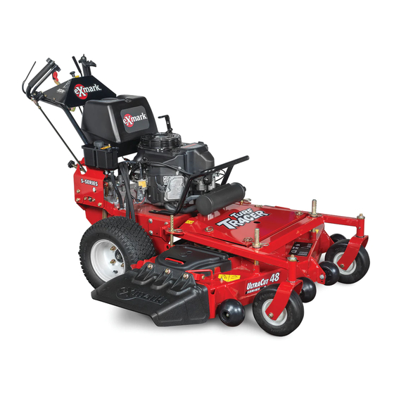
Exmark TURF TRACER S Series Setup Instructions
Hide thumbs
Also See for TURF TRACER S Series:
- Operator's manual (48 pages) ,
- Operator's manual (48 pages) ,
- Setup instruction (3 pages)
Advertisement
Quick Links
Loose Parts
Use the chart below to verify that all parts have been shipped. Part numbers not shown are available on the dealer
extranet.
Dealer Pack
Part #
107-4543
322-10
3256-3
104-8300
323-6
3290-357
98–5975
1-806003
3272-5
1-808280
322-9
3296-29
3220-16
1-303335
1-303287
103-2106
1-603511
Literature Pack
Manual, Operator's
Manual, Engine Operator's
Uncrating the Unit
1. Leaving the unit on the pallet, place the upper handle
assembly and the fuel tank at the rear of the machine.
2. Remove the bolt bag from under the mower deck
belt shield.
3. Refer to the parts manual to help you identify and
locate the parts and their proper position.
© 2012—Exmark Mfg. Co., Inc.
P.O. Box 808
Beatrice, NE 68310
Description
Clamp, Tank
Screw, HH 5/16-18 x 2
Washer, 5/16 Std
Nut, Nyloc 5/16-18 Flg
Screw, HH 3/8-16 x 1 inch
Nut, Whizlock 3/8-16 inch
Washer, Spring Disc
Hairpin, Cotter
Pin, Cotter 3/32 x 1/2 inch
Pin, Clevis
Screw, HH 5/16-18 x 1 3/4 inch
Nut, Nyloc 5/16-18 inch
Nut, Jam 3/8-24 inch LH
Tie, Cable
Tie, Cable
Key, Exmark Logo
Key, Standard
TURF TRACER
For Serial Nos. 313,000,000 & Higher
Qty.
2
2
Installing the fuel tank.
2
2
4
Installing the handle assembly.
4
4
1
Installing the speed control rod.
1
1
2
2
Installing the wheel drive linkages.
2
2
Connecting wire harness.
4
1
Fill out the online warranty registration
form and place keys into literature
1
pack.
Installing the Fuel Tank
1. Install the fuel tank on top of the fuel tank support.
Secure each side of the tank with a clamp, 5/16-18 x
2 inch screw, washer, and 5/16 inch nyloc nut.
2. Attach the fuel supply hose to the bottom tank fitting
and secure with the clamp provided.
3. Attach the purge hose from the tee on the engine
(canister on CA units) to the top fitting of the fuel
tank as shown in Figure 1. Press the hose into the
slot on the tank to retain it.
S-SERIES
®
Setup Instructions
Use
Part No. 4501-436 Rev. A
Printed in the USA
All Rights Reserved
Advertisement

Related Manuals for Exmark TURF TRACER S Series


Summary of Contents for Exmark TURF TRACER S Series
- Page 1 (canister on CA units) to the top fitting of the fuel tank as shown in Figure 1. Press the hose into the slot on the tank to retain it. © 2012—Exmark Mfg. Co., Inc. Part No. 4501-436 Rev. A P.O. Box 808...
-
Page 2: Installing The Handle Assembly
3. Attach the inner wire of the throttle cable to the top hole in the throttle control lever as shown in Figure 3. 4. Loosen the clamp, install the throttle cable on the bottom side of the clamp, and pull on the cable to move the throttle linkage to the full throttle position. - Page 3 2. Insert the end of the linkage opposite the yoke into the end of the speed control lever located underneath the handle console from the right hand side and fasten with a hairpin from the bolt bag. 3. Connect the lower end of the speed control linkage to the speed control crank located at the top rear of the fuel tank support.
- Page 4 neutral lock latches (Figure 7). If the tire rotates in either direction, the length of the drive lever link will need to be adjusted. 3. Adjust the linkage length by loosening the jam nuts at both ends of the linkage and rotating the linkage in the ball joints.
-
Page 5: Servicing The Battery
Servicing the Battery Percent Voltage Maximum Charging Reading Charge Charger Interval Settings WARNING 11.7–12.0 0–25% 3 Hours 14.4 volts/4 CALIFORNIA amps Proposition 65 Warning 6 Hours or 11.7 or less 14.4 volts/2 Battery posts, terminals, and related More amps accessories contain lead and lead compounds, chemicals known to the State of California CAUTION to cause cancer and reproductive harm. -
Page 6: Servicing The Engine
Servicing the Engine The engine is shipped with oil; check oil level and if necessary fill to the appropriate level. Exmark 4-Cycle Premium Engine Oil is recommended. Refer to the Engine Owner’s Manual for an acceptable alternative. Servicing the Hydraulic Oil The machine is shipped with hydraulic oil in the reservoir.